
ATP 6-02.70
TECHNIQUES FOR SPECTRUM MANAGEMENT OPERATIONS
DECEMBER 2015
DISTRIBUTION RESTRICTION. Approved for public release; distribution is unlimited.
*This publication supersedes FM 6-02.70, dated 20 May 2010.
HEADQUARTERS, DEPARTMENT OF THE ARMY
This publication is available at Army Knowledge Online
(https://armypubs.us.army.mil/doctrine/index.html).
To receive publishing updates, please subscribe at
http://www.apd.army.mil/AdminPubs/new_subscribe.asp

*ATP 6-02.70 (FM 6-02.70)
Distribution Restriction: Approved for public release; distribution is unlimited.
*This publication supersedes FM 6-02.70, dated 20 May 2010.
i
Army Techniques Publication
No. 6-02.70
Headquarters
Department of the Army
Washington, DC, 31 December 2015
TECHNIQUES FOR SPECTRUM MANAGEMENT
OPERATIONS
Contents
Page
PREFACE.............................................................................................................. iv
INTRODUCTION .................................................................................................... v
Chapter 1 OVERVIEW ........................................................................................................ 1-1
Electromagnetic Spectrum ................................................................................. 1-1
Definition ............................................................................................................. 1-3
Objective ............................................................................................................. 1-4
Core Functions ................................................................................................... 1-5
Army Spectrum Management Operations Process ............................................ 1-5
Chapter 2 TACTICAL STAFF ORGANIZATION AND PLANNING ................................... 2-1
Spectrum Management Operations for Corps and Below .................................. 2-1
Division, Brigade and Battalion Spectrum Operations ....................................... 2-3
Spectrum Managers Assigned to Cyber Electromagnetic Activity Working
Group .................................................................................................................. 2-3
Cyber Electromagnetic Activities Element .......................................................... 2-4
Tips for Spectrum Managers .............................................................................. 2-6
The Military Decisionmaking Process ................................................................ 2-7
Support to the MDMP Steps ............................................................................... 2-8
The Common Operational Picture .................................................................... 2-10
Chapter 3 SUPPORT TO THE WARFIGHTING FUNCTIONS ........................................... 3-1
Movement and Maneuver ................................................................................... 3-1
Intelligence ......................................................................................................... 3-1
Fires .................................................................................................................... 3-1
Sustainment ........................................................................................................ 3-2
Mission Command .............................................................................................. 3-2

Preface
ii ATP 6-02.70 31 December 2015
Protection ............................................................................................................ 3-4
Chapter 4 JOINT TASK FORCE CONSIDERATIONS ....................................................... 4-1
Inputs and Products of Joint Task Force Spectrum Managers ........................... 4-1
Joint Frequency Management Office .................................................................. 4-1
Joint Spectrum Management Element ................................................................ 4-3
Spectrum Management Support to Defense Support of Civil Authorities ........... 4-6
Chapter 5 SPECTRUM MANAGEMENT OPERATIONS TOOLS ...................................... 5-1
Tool Considerations ............................................................................................ 5-1
Joint Spectrum Interference Resolution Online ................................................ 5-11
Joint Spectrum Data Repository ....................................................................... 5-11
Appendix A SPECTRUM MANAGEMENT TASK LIST ........................................................ A-1
Appendix B CAPABILITIES AND COMPATIBILITY BETWEEN TOOLS............................ B-1
Appendix C SPECTRUM PHYSICS ...................................................................................... C-1
Appendix D SPECTRUM MANAGEMENT LIFECYCLE....................................................... D-1
Appendix E MILITARY TIME ZONE DESIGNATORS .......................................................... E-1
GLOSSARY .......................................................................................... Glossary-1
REFERENCES .................................................................................. References-1
INDEX ......................................................................................................... Index-1
Figures
Figure 1-1. Electromagnetic spectrum competition ............................................................... 1-3
Figure 1-2. The electromagnetic operational environment (EMOE) ...................................... 1-4
Figure 1-3. Army spectrum management operations process ............................................... 1-6
Figure 2-1. Use of the electromagnetic spectrum .................................................................. 2-2
Figure 2-2. CEMA working group organizational framework ................................................. 2-5
Figure 2-3. Key SMO inputs to the MDMP............................................................................. 2-8
Figure 3-1. Spectrum situational awareness system and CJSMPT support to mission
command ............................................................................................................ 3-3
Figure 4-1. Interagency workflow in a joint task force environment ....................................... 4-1
Figure 4-2. JFMO structure .................................................................................................... 4-2
Figure 4-4. Spectrum manager inputs for a JSME ................................................................ 4-6
Figure 4-5. Spectrum management support during domestic operations .............................. 4-8
Figure 5-1. S2AS and supporting equipment ......................................................................... 5-2
Figure 5-2. S2AS in use by Soldiers ...................................................................................... 5-3
Figure 5-3. S2A2 functional relationships .............................................................................. 5-4
Figure A-1. The SMO to EW collaboration process ............................................................... A-9
Figure A-2. The G-6 or S-6 spectrum manager’s tasks ...................................................... A-10
Figure A-3. The CEMA element tasks ................................................................................. A-12
Figure A-4. SMO collaboration tasks ................................................................................... A-13
Figure C-1. Waveform characteristics .................................................................................... C-1

Preface
31 December 2015 ATP 6-02.70 iii
Figure C-2. Wavelength relationship ..................................................................................... C-2
Figure C-3. Transmission and propagation of electromagnetic waves ................................. C-3
Figure E-1. World military time zone designator chart ...........................................................E-2
Tables
Table 4-1. Agency inputs to the JFMO ................................................................................... 4-2
Table 4-2. Products of the JFMO ........................................................................................... 4-3
Table 4-3. Agency inputs to the JSME ................................................................................... 4-4
Table 4-4. Products of the JSME............................................................................................ 4-5
Table B-1. Compatibility between SMO tools .........................................................................B-1
Table B-2. SMO tool capabilities ............................................................................................B-2
Table D-1. Call signs, call words, suffix and expander ......................................................... D-5
Table D-2. Data input for JSIR offline reporting .................................................................... D-7
Table E-1. Example of world time zone conversion (standard time) ......................................E-3

iv ATP 6-02.70 31 December 2015
Preface
ATP 6-02.70, Techniques for Spectrum Management Operations, establishes Army doctrine for Army spectrum
management operations (SMO). This publication provides overarching doctrinal guidance to Army spectrum
users and describes how spectrum managers support commanders through the warfighting functions, the military
decisionmaking process, and the common operational picture (COP). This ATP provides technical descriptions
of the SMO tool’s capabilities and compatibility with other tools, as well as how to use these tools in the execution
of spectrum management operations in unified land operations.
The principal audience for ATP 6-02.70 is Army commanders, leaders and staffs at all levels, members of the
Army profession and Department of Defense (DOD) contractors whose duties involve spectrum management
operations. Commanders and staffs of Army headquarters serving as joint task force or multinational headquarters
should also refer to applicable joint or multinational doctrine concerning the range of military operations and joint
or multinational forces. Trainers and educators throughout the Army will also use this publication.
Commanders, staffs, and subordinates ensure their decisions and actions comply with applicable U.S.,
international, and, in some cases, host-nation laws and regulations. Commanders at all levels ensure their Soldiers
operate in accordance with the law of war and the rules of engagement. (See FM 27-10)
ATP 6-02.70 uses joint terms where applicable. Selected joint and Army terms and definitions appear in both the
glossary and the text. Terms for which this ATP is the proponent are marked with an asterisk (*) in the glossary.
Definitions for which ATP 6-02.70 is the proponent publication are boldfaced in the text. For other definitions
shown in the text, the term is italicized and the number of the proponent publication follows the definition.
This publication applies to the Active Army, Army National Guard/Army National Guard of the United States,
and United States Army Reserve unless otherwise stated.
The proponent of ATP 6-02.70 is the U.S. Army Cyber Center of Excellence. The preparing agency is the Cyber
Center of Excellence Doctrine Branch, United States Army Cyber Center of Excellence. Send comments and
recommendations on a DA Form 2028 (Recommended Changes to Publications and Blank Forms) to Commander,
U.S. Army Cyber Center of Excellence and Fort Gordon, ATTN: ATZH-DT (ATP 6-02.70), 506 Chamberlain
Avenue, Fort Gordon, Georgia 30905-5735, or by e-mail to usarmy.gordon.cybercoe.mbx.gord-fg-
31 December 2015 ATP 6-02.70 v
Introduction
ATP 6-02.70, Techniques for Spectrum Management Operations is the Army’s doctrine for spectrum
management operations in support of unified land operations. This publication replaces FM 6-02.70, Army
Electromagnetic Spectrum Operations and introduces the subject in the form of an Army techniques
publication. Aligned with FM 6-02, Signal Support to Operations and FM 3-38, Cyber Electromagnetic
Activities, this publication provides the Army’s current doctrine with regard to spectrum management
operations.
ATP 6-02.70 contains updated doctrinal information and makes numerous changes to the information found
in FM 6-02.70. The most significant change is the introduction and use of the acronym SMO (spectrum
management operations), introduced in FM 6-02, Signal Support to Operations. This change provides less
confusion to Soldiers and legitimizes the acronym already in use within the spectrum community. The content
in ATP 6-02.70 aligns with FM 6-02.70 however, changes to current Army doctrine and the Army’s emphasis
on cyber electromagnetic activities prompted new terminology.
Throughout this publication, when using the term spectrum, this refers to the radio frequency spectrum of the
electromagnetic spectrum. The electromagnetic spectrum encompasses the entire range of frequencies while
the term spectrum refers to the part of the electromagnetic spectrum that is transmitted and received by
various types of equipment.
This publication contains five chapters and five appendixes—
Chapter 1 provides an overview of spectrum management operations, states the objectives, and describes
spectrum management operations core functions.
Chapter 2 discusses spectrum management operations support and input to the military decisionmaking
process and briefly describes the common operational picture. Spectrum managers provide support at every
step of the military decisionmaking process.
Chapter 3 links Army spectrum management operations to the warfighting functions, describes how
spectrum management operations support, and enables commander’s efforts as they exercise mission
command.
Chapter 4 describes spectrum information and products necessary at the corps and joint task force levels.
Spectrum managers are located within three organizations in a joint task force: the joint frequency
management office, the joint spectrum management element, and the cyber electromagnetic activities
(CEMA) element. These agencies have a wide variety of inputs, collaboration, and products. This chapter
shows input and products from different joint agencies displayed in table format.
Chapter 5 is an overview of the many useful tools spectrum managers use in support of unified land
operations. These tools operate within a network-centric environment using shared databases within the
spectrum community.
Finally, the ATP contains five appendixes containing standard tasks and steps that describe spectrum
management operations related tasks.
Appendix A describes the electromagnetic spectrum manager task list and each supporting sub-tasks. This
appendix also contains flow charts that show the collaboration process between electromagnetic spectrum
managers and the CEMA element.
Appendix B provides spectrum management operations tool capabilities and compatibility between software
systems. These net-centric systems are in many cases linked and accessible through Nonsecure Internet
Protocol Router Network (NIPRNET) and SECRET Internet Protocol Router Network (SIPRNET).
Appendix C provides basic electromagnetic physics and underlying principles of the electromagnetic
spectrum.

Introduction
vi ATP 6-02.70 31 December 2015
Appendix D introduces the 12-step spectrum management lifecycle. This process serves as a guide to follow
in establishing a functional and efficient spectrum management program. The lifecycle encompasses the
complete process of providing spectrum management operations support to the commander and is applicable
to all spectrum managers regardless of duty location. The Army spectrum management lifecycle mirrors the
joint task force lifecycle adapted for the Army spectrum manager.
Appendix E provides the reader with an overview of the military time zone designators. This appendix
describes time zones for civilian and military uses. The chart, included in this appendix, provides a valuable
tool to reference time zones in all parts of the world.

31 December 2015 ATP 6-02.70 1-1
Chapter 1
Overview
This chapter introduces the frequency spectrum, provides an overview of spectrum
management operations, and describes the core functions related to spectrum
management operations within the context of Army operations. This chapter also
provides an overview of spectrum management operations task.
ELECTROMAGNETIC SPECTRUM
1-1. The electromagnetic spectrum is a continuum of all electromagnetic waves arranged according to
frequency and wavelength. Multiple radiated signals coexist in the same physical space and selectively
detected using the appropriate equipment and channel. The spectrum extends from below the frequencies
used for radio (at the long-wavelength end) through gamma radiation (at the short-wavelength end). Divided
into alphabetically designated bands for specific wavelengths and frequency ranges, the spectrum
encompasses wavelengths from thousands of kilometers to a fraction of an atom. Radio signals are able to
coexist in the same physical space. Radio frequency spectrum is the continuum of frequencies of
electromagnetic radiation from 3,000 Hertz (Hz) or 3 kilohertz (kHz) to 300 gigahertz (GHz). Isolation of
multiple users of spectrum is possible by allocating different bands of this continuum to them.
Note. See Appendix C for an overview of spectrum physics.
Constrained Environment
1-2. Gaining and maintaining control of the electromagnetic spectrum is a critical requirement for the
commander. From communications, to intelligence collection, to electronic warfare, all forces, and
supporting agencies depend on the electromagnetic spectrum to execute operations in the air, land, maritime,
space, and cyberspace domains. Within the electromagnetic spectrum, joint forces contend with civil
agencies, commercial entities, allied forces, and adversaries for use of a common electromagnetic spectrum
resource. This demand for electromagnetic spectrum use results in a constrained, congested, and contested
environment that affects operations across all domains and functions. This contention and competition
produces a constrained environment regarding how, when, and where to use electromagnetic spectrum
resources.
1-3. Congestion in the electromagnetic spectrum results when multiple users attempt to use the same
portions of the spectrum simultaneously. This competition and congestion can potentially lead to the
operational failure of systems during critical missions due to electromagnetic interference. Adversaries can
exploit modern technologies to develop sophisticated electronic attack capabilities, contesting the ability of
all military assets to access and use the electromagnetic spectrum.
1-4. Army spectrum managers’ tasks include planning, managing, coordinating, and providing policies and
regulations for the use of the electromagnetic spectrum. The Army shares spectrum related resources with
other Services, civilian counterparts, and friendly forces. Due to the large quantity of devices and forces using
the spectrum, portions maybe unavailable. Environmental factors such as solar activity and weather can
adversely affect SMO. The Army spectrum manager uses knowledge and spectrum management tools to
determine how to best support a mission with limited spectrum resources. Solutions can be as simple as
having a unit switch to a different frequency or as complex as adjusting the entire spectrum plan. There are
times when the commander prioritizes spectrum use to conduct operations.

Chapter 1
1-2 ATP 6-02.70 31 December 2015
Spectrum Dependent Devices
1-5. The spectrum manager is the commander’s resident expert who provides course of action (COA)
recommendations based on software modeling and simulation to mitigate spectrum use problems. The
spectrum manager is vital to ensuring all spectrum dependent devices (SDD) operate as intended without
suffering or causing harmful interference. Devices that utilize the electromagnetic spectrum to emit, receive,
monitor frequencies are referred to as SDDs. SDDs include any conceptual, experimental, developmental,
operational transmitter, receiver, or device that uses any portion or part of the electromagnetic spectrum.
1-6. SDD systems include, but are not limited to transmitter, receivers, command and control systems and
platforms, electronic warfare assets, sensors, beacons, navigational aids, radio and radio systems, radar
systems, remote controlled robotic equipment, manned and unmanned aircraft systems. Electromagnetic
interference is any electromagnetic disturbance that interrupts, obstructs, or otherwise degrades or limits the
effective performance of electronics or electrical equipment. It can be induced intentionally, as in some forms
of electronic warfare, or unintentionally, as a result of spurious emissions and responses and intermodulation
products.
Note. See CJCSM 3320.02F for further information on electromagnetic interference.
1-7. Spectrum users should understand that it is not a replaceable resource like fuel or ammunition. Once
the allotted spectrum to support a specific capability or system is in use, it is no longer available for use
depending upon system and environmental variables. The commander may need to operationally assess the
impact of sacrificing other potentially critical capabilities to ensure the use of another spectrum dependent
user. Spectrum management operations are the oversight of all characteristics of electromagnetic radiation.
The goal is to protect systems from harmful interference while allowing the optimum use of the spectrum.
The process is complex since the characteristics of electromagnetic radiation vary with time, space, and
frequency.
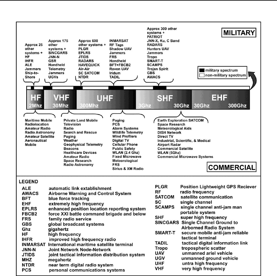
1-8. Figure 1-1, on page 1-3, displays a portion of the spectrum used by various systems and devices both
commercial and military that compete for these bands (acronyms in graphic are not essential to understanding
the text).
Overview
31 December 2015 ATP 6-02.70 1-3
Figure 1-1. Electromagnetic spectrum competition
DEFINITION
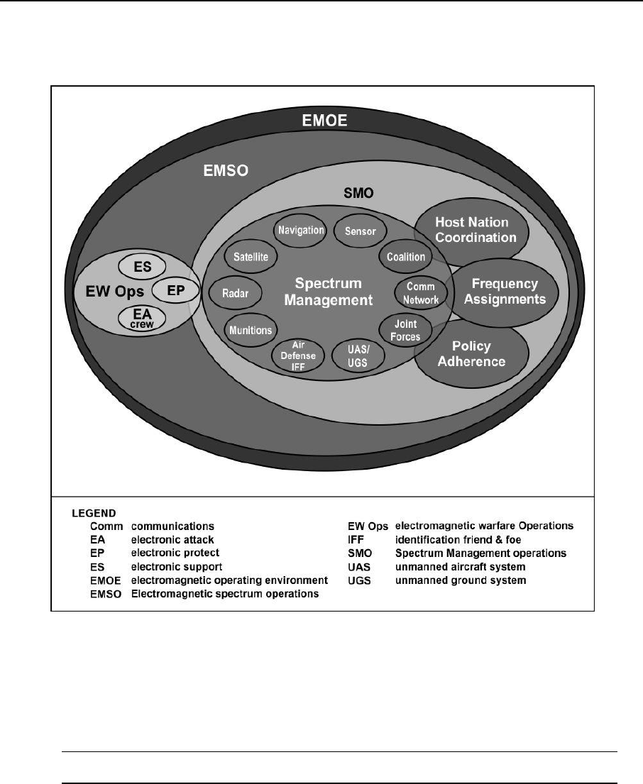
1-9. SMO are the interrelated functions of spectrum management, frequency assignment, host nation
coordination, and policy that together enable the planning, management, and execution of operations within
the electromagnetic operational environment (EMOE), during all phases of military operations. The portions
of the electromagnetic spectrum, experienced and influenced by military operations is the EMOE.
Electromagnetic spectrum operations include electronic warfare for which the Cyber Center of Excellence is
the proponent. Electromagnetic spectrum operations includes all activities in military operations to control
the spectrum. SMO is the management portion of electromagnetic spectrum operations. Figure 1-2, on page
1-4, depicts the various areas of responsibility as they pertain to EMOE.
1-10. Army spectrum managers coordinate and collaborate with spectrum managers working in joint
environments. Collaboration with joint personnel is common and necessary for the Army spectrum manager
while using the highly saturated and limited spectrum available. The primary goal of joint electromagnetic
spectrum operations is to enable SDD to perform their functions in the intended environment without causing
or suffering unacceptable interference. Joint electromagnetic spectrum operations are those activities
consisting of electronic warfare and joint electromagnetic spectrum management operations used to exploit,
Chapter 1
1-4 ATP 6-02.70 31 December 2015
attack, protect, and manage the electromagnetic operational environment to achieve the commander’s
objectives.
Figure 1-2. The electromagnetic operational environment (EMOE)
1-11. SMO is a supporting function or enabler for many of the Army unified land operations. SMO is a
primary component of CEMA, which consists of cyberspace operations, electronic warfare, and spectrum
management operations. CEMA enables the management of the electromagnetic spectrum in support of
mission command. These activities employ the same technologies, capabilities, and enablers to accomplish
assigned tasks resulting in the commander’s integration and synchronization across all command echelons
and warfighting functions as part of the operations process.
Note. Refer to ADRP 3-0 for further information.
OBJECTIVE
1-12. The objective of Army SMO is to ensure access to the electromagnetic spectrum in support of users
conducting the Army’s operational missions. SMO enables the allotment of the vital, but limited, natural
resource that directly supports operational forces throughout the world. The Army is dependent upon the use
of the radio frequency spectrum at all levels of unified land operations. An effective spectrum management
operations program enables electronic systems to perform their functions in the intended environment
without causing or suffering unacceptable performance.

Overview
31 December 2015 ATP 6-02.70 1-5
1-13. Commanders must have the ability to see the use of their assigned spectrum resources so they can
apply systematic management controls in the logistics and mission command arenas. The electromagnetic
spectrum is a vital warfighting resource that requires the same planning and management as other critical
resources such as fuel, water, and ammunition. Spectrum managers, with the appropriate expertise and tools,
ensure that commanders have adequate knowledge of the utilization of the frequency spectrum to make
decisions that positively influence accomplishment of their missions.
CORE FUNCTIONS
1-14. The SMO core functions determine the tasks and requirements of the Army spectrum manager. These
four functions are—
Spectrum Management: Spectrum management is the planning, coordinating, and managing
of joint use of the electromagnetic spectrum through operational, engineering, and administrative
procedures. Spectrum management consists of evaluating and mitigating electromagnetic
environmental effects, managing frequency records and databases, de-conflicting frequencies,
frequency interference mitigation, allotting frequencies, spectrum supportability assessments, and
electronic warfare coordination to ensure SDD operate as intended.
Frequency Assignment: The request and issuance of authorizations to use frequencies for
specific equipment such as combat net radio and Army common user systems is a task of frequency
assignment. This also includes the planning necessary for combat net radio, Army common user
systems, and associated systems. Examples of frequency assignment are assigning the frequencies
necessary to generate single-channel ground and airborne radio system (SINCGARS) hopsets,
providing frequencies for unmanned aerial systems and line of sight networks, or assigning
frequencies for the Warfighter Information Network-Tactical (WIN-T) network.
Host Nation (HN) Coordination: Each nation has sovereignty over its electromagnetic
spectrum within its geographic area and negotiates the use of the spectrum on a case-by-case basis.
A representative of the sovereign country evaluates each Department of Defense (DOD) request
for the use of spectrum based on the perceived potential for electromagnetic interference (EMI) to
local receivers. Use of military or commercial spectrum systems in host nations requires
coordination and negotiation that result in formal approvals and certifications.
Policy Adherence: The commanders ability to access and maneuver within the electromagnetic
spectrum is dependent on policy. Policy are those authoritative instruments from the national
strategic through the tactical level that nest and shape the spectrum management, frequency
assignment, and host nation coordination process. Countries coordinate global international
spectrum use through the International Telecommunications Union and the World Radio
Communication Conference. At the U.S. national level under U.S. Code Title 47, the division of
spectrum management responsibility rests with the National Telecommunications and Information
Administration (NTIA) for federal frequencies and the Federal Communications Commission for
non-federal frequencies. The Military Communications-Electronics Board (MCEB) is the main
coordinating body for spectrum matters among DOD components. Overseas, the U.S. mission,
working with DOD strategic partners, negotiates treaties and agreements when stationed or
training U.S. forces are within a host nation. These agreements establish lines of communications
between the host-nation and senior military commands to negotiate spectrum usage in support of
training and operations. Examples of policy instruments include International
Telecommunications Union and World Radio Communication Conference agreements, status of
forces agreements, host-nation agreements, operational orders, U.S. Code Title 47, and operations
plans.
ARMY SPECTRUM MANAGEMENT OPERATIONS PROCESS
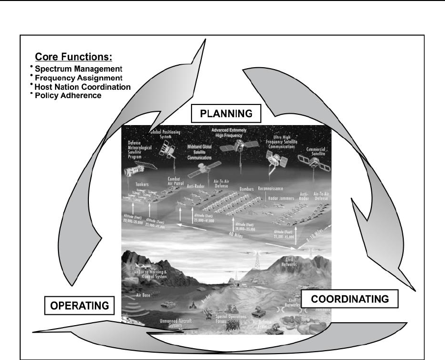
1-15. The Army SMO process comprises three interacting and continuous activities: planning, coordinating,
and operating (see figure 1-3, on page 1-6). The Army SMO process is a means of planning that continues
through all phases of the mission. During the execution of unified land operations, these functions occur
concurrently.
Chapter 1
1-6 ATP 6-02.70 31 December 2015
Figure 1-3. Army spectrum management operations process
PLANNING
1-16. SMO planning includes the identification of spectrum requirements for training, pre-deployment,
deployment, and reconstitution of Army forces, both in and outside the continental U.S. SMO planning is an
on-going process that must be deliberate as well as dynamic to support unified land operations. It requires
the collection, storage, and protection of critical spectrum data, and assured access to this data by spectrum
planners on a global scale. Additionally, planning for the establishment of lines of communications for
coordination of spectrum use with national and international government and non-government agencies is
critical to the spectrum planning process.
1-17. The CEMA element and the CEMA working group have an assigned spectrum manager that provides
expertise in planning and coordinating horizontally and vertically to support unified land operations. The
spectrum manager’s primary role is to assist with de-conflicting detection and delivery assets through the
planning and targeting processes.
COORDINATING
1-18. Coordination ensures initial spectrum availability and supportability for operations. Lines of
communication for coordinating spectrum allocation at the national and international level are primarily a
matter of policy established in the planning process. Enemy nations or their military do not receive U.S. host
nation coordination. Spectrum managers coordinate adjacent countries spectrum, particularly if forces stage,
train, or operate within these countries, to include airspace, sovereign waters, and frequencies for satellites.
Coordination at the operational Army level requires prior coordination as well as a dynamic, instantaneous
collaboration tool.

Overview
31 December 2015 ATP 6-02.70 1-7
1-19. Staff Coordination-Spectrum managers coordinate with various staff sections to ensure effective
SMO. Commanders engage spectrum managers early in the planning process when forecasting for the use of
spectrum dependent devices. Staff coordination, electronic warfare (EW) coordination, communications
security coordination, satellite coordination, frequency deconfliction, frequency interference resolution, and
joint restricted frequency lists are SMO tasks that support spectrum functions.
1-20. Spectrum managers work with many systems that are not exclusively communications systems. They
must interact with other staff members to provide guidance, assistance, and advice to the commander
regarding the use and prioritization of the spectrum. Systems such as unmanned aerial systems, common user
jammers, radars, navigational aids, and sensors all use the spectrum for operation. Their extensive use and
unique operating characteristics necessitate special planning and coordination to mitigate frequency
fratricide.
1-21. Unified Action Partners-Coordinating spectrum use is the process of collaborating with unified action
partners. Unified action partners are those military forces, governmental and nongovernmental organizations,
and elements of the private sector with which Army forces plan, coordinate, synchronize, and integrate during
the conduct of operations. This function ensures initial spectrum availability and supportability for
operations. Lines of communication for coordinating spectrum allocation at the national and international
levels are primarily a matter of policy established in the planning process.
1-22. Host Nation Coordination-Use of military or commercial spectrum systems in host nations requires
coordination and negotiation that result in formal approvals and certifications. Coordination for use of the
spectrum in host nations is required if forces stage, train, or operate within these countries to include airspace,
sovereign waters, and frequencies for satellites. Prior coordination as well as dynamic, immediate
collaboration tools results in a seamless use of the spectrum. Failure to request frequency usage in a timely
manner results in the inability to operate communications equipment in the host nation. Each nation has
sovereignty over its spectrum within its geographic area and negotiates the use of spectrum on a case-by-case
basis. A representative of the sovereign country evaluates each DOD request for the use of spectrum based
on the perceived potential for EMI to local receivers.
1-23. The host nation spectrum worldwide database online (HNSWDO) is a tool, used by military service
department spectrum management offices, to track DOD host nation spectrum supportability request to
determine equipment supportability. Host nation access request are added to HNSWDO by the sponsoring
service spectrum management agency. Requests are sent to the respective combatant command’s joint
frequency management office (JFMO) to annotate comments in HNSWDO for visibility. Tactical spectrum
managers coordinate frequency assignments through established spectrum coordination channels. Spectrum
management offices assuming the role of the Joint Spectrum Management Element (JSME) may be delegated
by the combatant command JFMO to perform person-to-person host nation coordination in support of joint
task force operations.
1-24. Electronic Warfare Coordination-The spectrum manager should be an integral part of all EW
planning to provide awareness of spectrum conflicts initiated by friendly systems for personnel protection,
enemy exploitation, or enemy denial. The advent of common user “jammers” has made this awareness and
planning critical for the spectrum manager. In addition to jammers, commanders and staffs must consider
non-lethal weapons that use electromagnetic radiation. EW coordination normally takes place in the CEMA
working group. It may take place in the EW Cell if it is operating under a joint construct or operating at a
special echelon.
1-25. Communications Security Coordination-Spectrum managers work closely with communications
security personnel to ensure the proper keying material for the appropriate frequency resource of SINCGARS
loadsets. Spectrum managers only manage and process communications security for SINCGARS by way of
loadsets. They do not manage communications security for other emitters.
1-26. Satellite Coordination-Spectrum managers coordinate with satellite managers to maintain awareness
of channels (frequencies) used by satellite communications systems. The satellite manager generates and
processes satellite access requests. Spectrum managers receive and verify the information provided in the
satellite access request for all satellite communications. Once approved, the spectrum manager enters the
frequencies into the spectrum database for frequency deconfliction with all other emitters in the area of
operations.

Chapter 1
1-8 ATP 6-02.70 31 December 2015
1-27. Frequency Deconfliction-Frequency deconfliction is a systematic management procedure to
coordinate the use of the electromagnetic spectrum for operations, communications, and intelligence
functions. Frequency deconfliction is one element of electromagnetic spectrum management and applies
practices to minimize or prevent spectrum dependent devices from suffering or causing interference while
being used as intended. It is easy to confuse EMI mitigation with frequency de-confliction. The main
difference is that frequency deconfliction occurs during the planning phase of a mission while EMI mitigation
occurs during mission execution.
1-28. Joint Restricted Frequency List (JRFL)-The JRFL is a concise list of highly critical protected
frequencies and nets categorized as Taboo, Protected, and Guarded. Commanders and planners prohibit
jamming or attacking frequencies listed on the JRFL. The JRFL includes command channels of senior
commanders and safety-of-life frequencies used by local civilian noncombatants. Usually listed in the JRFL
are international distress, safety, and controller frequencies.
1-29. High priority nets, bands, and frequencies are protected from friendly electronic attack (EA) when
possible however, the concern of the spectrum manager is to ensure that all friendly systems have the ability
to operate unimpaired. This can be accomplished by simply adding the offending jammer to a database and
using spectrum management techniques (such as changing frequencies, assignments, or moving to an
unaffected area) to accomplish the mission. The spectrum manager has tools that can identify potential
frequency fratricide if properly utilized, ultimately saving lives. Refer to paragraph 5-36 and appendix A for
further information on the JRFL.
Note. Use of the JRFL will not deconflict all frequency issues. The JRFL does not provide
communications planners with frequencies EA systems transmit or the technical information
needed to deconflict EA from friendly operations including lower echelon maneuver forces.
Efficient utilization of spectrum management tools identifies potential interference and frequency
conflicts during mission planning reducing frequency fratricide.
1-30. Interference Resolution-The spectrum manager performs interference resolution at the echelon
receiving the interference. Interference is the radiation, emission, or indication of electromagnetic energy;
either intentionally or unintentionally causing degradation, disruption, or complete obstruction of the
designated function of the electronic equipment affected. The spectrum manager should utilize available
near-real time monitoring and analysis capabilities to aid in the interference resolution. The reporting end
user is responsible for assisting the spectrum manager in tracking, evaluating, and resolving interference.
Appendix D contains further information on frequency interference resolution and reporting.
OPERATING
1-31. The operating activity for SMO enables and sustains the functions of planning and coordinating. It
includes the process to plan, conduct, coordinate, and sustain spectrum operations. SMO ensures the efficient
use of allocated spectrum and associated frequencies in a given area of operations. Spectrum managers use
the operating function to enable dynamic, near instantaneous frequency assignment, re-assignment,
interference mitigation, and frequency deconfliction across all users in an area of operations. The architecture
provides for interoperability with U.S. national, local government and non-government agencies as well as
unified action partners.

31 December 2015 ATP 6-02.70 2-1
Chapter 2
Tactical Staff Organization and Planning
SMO is dynamic and requires continuous coordination among all echelons and
warfighting functions both laterally and horizontally to mitigate harmful interference.
This chapter describes SMO functions for staff organizations at the corps and below
level, and provides an overview of division, brigade and battalion spectrum operations.
This chapter also describes how SMO is incorporated within the military
decisionmaking process and shows how the spectrum manager supports the common
operational picture.
SPECTRUM MANAGEMENT OPERATIONS FOR CORPS AND
BELOW
2-1. The goal of tactical SMO is to protect and provide access to the spectrum so that it serves the needs of
friendly forces. Spectrum operations at the tactical level can be a very complicated and time-consuming
process.
2-2. In the past, the bulk of spectrum management was concerned with networked communications emitters
and combat net radio networks. Today, the tactical environment includes a vast number of SDD operating in
all regions of the spectrum across the battlefield. The key to sound spectrum management is having an
understanding of all emitters and receivers in the operational area while being able to deconflict these
systems. As stated earlier, the commander must be aware that the spectrum is a limited resource and that
efficient spectrum use is critical to enabling the warfighting functions.
Note. SMO is bottom driven for requirements while top fed for resources. The brigade combat
teams represent the pointy end of the spear and it is critical that the staff at each echelon captures
all requirements to ensure commanders receive the proper resources. Maximizing the use of the
spectrum requires coordination between EW, network operations, intelligence staffs, and other
known users.
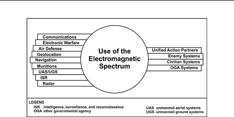
2-3. Figure 2-1, on page 2-2, illustrates the competing systems that cause challenges throughout the
spectrum. The assistant chief of staff for communications, signal staff officer (G-6) or the battalion or brigade
signal staff officer (S-6) is responsible for coordination with all spectrum users within a given operational
area, to identify all requirements for spectrum access, and to conduct frequency deconflictionThey also
maintain a database of all known emitters and receivers in the operational area to identify and prioritize
competing systems for frequency assignments.
Chapter 2
2-2 ATP 6-02.70 31 December 2015
Figure 2-1. Use of the electromagnetic spectrum
CORPS SPECTRUM OPERATIONS
2-4. There are three spectrum managers within the G-6 staff and one located in the assistant chief of staff,
operations section (G-3). The spectrum management chief is the principle advisor to the commander for
spectrum management related matters and is the Army spectrum authority in a corps operational area. Two
other spectrum managers assist the spectrum management chief in performing corps spectrum management
duties. Normally, one assists the network planners and the other manages the signal operating instructions
(SOI) and other functions that fall outside of the network. The spectrum manager assigned to the G-3
conducts electronic warfare deconfliction, coordination and planning and advises the Electronic Warfare
Officer (EWO) on potential spectrum conflicts and issues. The corps spectrum management chief may be
designated as the joint task force spectrum manager if the Army is the lead service in a joint operation.
2-5. At the corps, spectrum operations place more emphasis on host nation coordination, establishing policy
and procedure to assure the necessary spectrum is available for operations, and ensuring subordinate units
efficiently use spectrum resources. The spectrum manager accomplishes this through the development of
standard operating procedures based on joint and service regulations, instructions, policies, and doctrine.
2-6. The corps spectrum manager’s responsibilities include the following—
Assist in the development and publishing of communications annexes and appendices.
Develop, produce, and disseminate spectrum operations standard operating procedures.
Create and send a data call message (see appendix A for a description of data call message).
Determine if the unit’s devices have spectrum supportability.
Coordinate host nation spectrum use.
Develop, create, and distribute the SOI.
Coordinate and participate with other staff sections and cells.
Coordinate with unified action partners.
Perform prescribed reviews for frequency use and requirements.
Provide frequency-engineering support for communications network design and operations.
Conduct EMI identification, analysis, mitigation, and reporting.
JRFL production and promulgation.
Advise the EWO on potential spectrum conflicts and issues.
On order, assume the roles and responsibilities of the joint task force joint spectrum management
element (JSME).

Tactical Staff Organization and Planning
31 December 2015 ATP 6-02.70 2-3
Note. See CJCSM 3320.01 for JSME responsibilities.
DIVISION, BRIGADE AND BATTALION SPECTRUM OPERATIONS
2-7. The roles of division and brigade spectrum managers are similar at their respective levels. The brigade
spectrum manager gathers, validates, and forwards requirements for all spectrum support to the division. In
turn, the division forwards its requirements to the next higher authority.
2-8. There are two spectrum managers at the G-6 and one in the G-3 per division. Normally, one spectrum
manager is responsible for the network frequency assignments to include satellite access authorization
deconfliction. The network planners design the network that determines the spectrum requirement and the
spectrum manager uses this design to request the spectrum requirements necessary for the communications
network. Another spectrum manager is responsible for combat net radio, radar, and other systems
requirements. The G-3 spectrum manager provides support for fires, EW deconfliction, and coordination and
planning.
2-9. Brigade spectrum managers are located in the S-6 and S-3 to maintain visibility of all spectrum related
matters in the brigade. The brigade and in some instances the battalion (selected maneuver units) is currently
the lowest echelon to have a spectrum manager. Echelons lower than brigades or battalions coordinate their
spectrum requirements and concerns through the brigade spectrum manager.
2-10. The division, brigade or battalion spectrum manager’s responsibilities include the following—
Advise the commander in spectrum prioritization and implementation.
Build and distribute SINCGARS loadsets.
Request, obtain, and distribute frequencies for all devices.
Perform spectrum network analysis to engineer line of sight radio links and assign frequencies.
Advise network planners in matters concerning spectrum management.
Maintain and update spectrum related databases.
Advise and coordinate with EW personnel for frequency planning and use.
Perform spectrum analysis and frequency deconfliction.
Coordinate satellite frequency deconfliction.
Conduct electromagnetic interference identification, analysis, mitigation, and reporting.
Coordinate with Army Aviation Units to determine and mitigate interference.
Perform situational awareness and analysis using a spectrum analyzer or monitoring receiver.
Perform propagation analysis for high frequency and tropospheric scatter systems.
Assist in JRFL production and promulgation.
Assist in spectrum supportability determinations.
Develop and maintain the EMOE picture by capturing and recording all unit SDDs with
appropriate tools and databases.
On order, the Division SMO assumes the roles and responsibilities of the joint task force J-6 JSME
as required.
Note. See CJCSM 3320.01 for JSME responsibilities.
SPECTRUM MANAGERS ASSIGNED TO CYBER
ELECTROMAGNETIC ACTIVITY WORKING GROUP
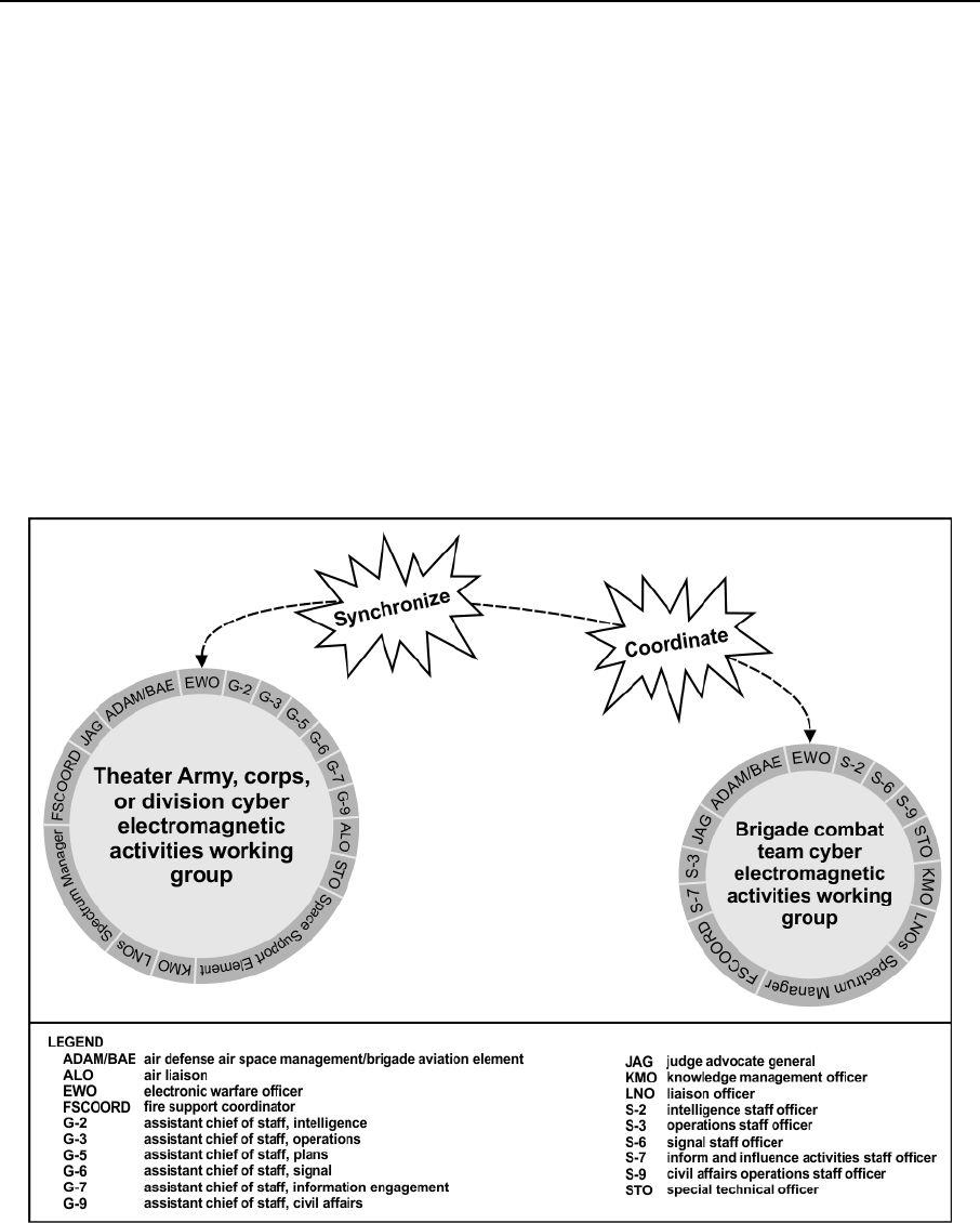
2-11. When established, the CEMA working group is accountable for integrating CEMA and related actions
into the concept of operations. CEMA working groups do not add additional structure to an existing
organization. The CEMA working group is a collaborative staff meeting led by the EWO to analyze,
coordinate, and provide recommendations for a particular purpose, event, or function.

Chapter 2
2-4 ATP 6-02.70 31 December 2015
2-12. A spectrum manager’s inherent duties include many affiliations and activities based on their
assignment. Spectrum managers participate in CEMA working groups or CEMA elements as required by the
command. As a member of these groups, they provide the specialized technical knowledge to enable the
working group or element to provide the commander with expert knowledge on spectrum related activities.
2-13. The CEMA working group is responsible for coordinating horizontally and vertically to support unified
land operations and primarily deconflict detection and delivery assets through the planning and targeting
processes. (FM 3-38) Staff representation within the CEMA working group may include the G-2 (S-2),
information operations officer, battalion or brigade civil affairs operations staff officer assistant chief of staff,
civil affairs operations, fire support officer, space support element, judge advocate general representative (or
appropriate legal advisor), and a joint terminal attack controller when assigned. Based on requirements
capabilities, the CEMA working group staff may delete or modify members. The CEMA working group
augments the function of the permanently established CEMA element. When scheduled, the CEMA working
group is a critical planning event integrated into the staff’s battle rhythm.
2-14. The CEMA working group requires a spectrum manager positioned within the working group to
deconflict spectrum, identify conflicts, and mitigate possible frequency fratricide during the planning phase
of all forms of fire. Frequency fratricide is the unintentional interruption of friendly frequencies. Frequency
fratricide can cause many problems for operations and prevention is the key. Spectrum managers provide the
working group with frequency options and advice that follows internal and external policies that minimize
frequency fratricide.
2-15. To accomplish the task of integration of CEMA into all unit operations, the EWO leads the CEMA
working group, which determines EW requirements and integrates these requirements into the unit’s planning
and targeting processes. One role of the EW team in CEMA is to coordinate the operational targeting of
effects in cyberspace.
CYBER ELECTROMAGNETIC ACTIVITIES ELEMENT
2-16. The CEMA element consists of personnel that plan, prepare, and synchronize cyberspace operations,
EW, and SMO. The element, led by the electronic warfare officer (EWO), provides staffs expertise for the
planning, integration, and synchronization of cyberspace operations, EW, and SMO. When the mission
dictates, the CEMA element can leverage other additional skill sets of the CEMA working group. When
operating in a joint, multinational, or intergovernmental environment, commanders may reorganize their
staffs to better align with higher headquarters. The CEMA element is an organic organization in brigade,
division, corps, and theater Army staffs (FM 3-38).
2-17. The key personnel involved in planning and coordination in the CEMA element are the—
EW staff.
Spectrum manager.
Assistant chief of staff, intelligence (G-2) or battalion or brigade intelligence staff officer (S-2).
Assistant chief of staff, signal (G-6 [S-6]) staff.
ELECTRONIC WARFARE STAFF
2-18. The EWO functions as the commander’s designated staff officer for the planning, integration,
synchronization, and assessment of CEMA and uses other members of the staff to integrate CEMA into the
commander’s concept of operations. The EWO is responsible for understanding all applicable classified and
unclassified policy relating to cyberspace, EW, and electromagnetic spectrum to properly inform the
commander on the proper planning, coordination, and synchronization of CO, EW and SMO. The EWO is
the commander’s subject matter expert on CREW.
SPECTRUM MANAGER
2-19. As a key member of the CEMA element, the spectrum manager coordinates spectrum use for a wide
variety of communications and electronic resources. Some of the primary functions the spectrum manager
provides include—
Tactical Staff Organization and Planning
31 December 2015 ATP 6-02.70 2-5
Coordinates the preparation of the JRFL and issuance of emissions control guidance.
Coordinates frequency allotment, assignment, and use.
Coordinates electromagnetic deception plans and operations in which assigned communications
resources participate.
Coordinates measures to eliminate, moderate, or mitigate electromagnetic interference.
Coordinates with higher echelon spectrum managers for electromagnetic interference resolution
they cannot resolve internally.
Assists the EWO in issuing guidance to the unit (including subordinate elements) regarding
deconfliction and resolution of interference problems between EW systems and other friendly
systems.
Participates in the CEMA working group to deconflict friendly spectrum requirements with
planned EW, CO, and intelligence collection.
Synchronizes frequency allotment and assignment use with the G-6 or J-6 spectrum manager.
2-20. The working groups may include, but are not limited to, key members of operations, intelligence,
communications, training, air liaison officer, fires, special technical operations, and liaisons from supported
units. Figure 2-2. CEMA depicts the working group organizational framework.
Figure 2-2. CEMA working group organizational framework

Chapter 2
2-6 ATP 6-02.70 31 December 2015
TIPS FOR SPECTRUM MANAGERS
2-21. The following tips provide guidance to spectrum managers for further understanding of the types and
number of emitter devices in their unit. This information leads to a firm understanding of the spectrum
requirements and mitigates the need to request resources multiple times.
Obtain a detailed in-briefing from the outgoing spectrum manager.
Meet and establish a rapport with other staff entities, such as electronic warfare, intelligence,
communications, operations, cyber, and logistics. This builds avenues for coordination during
mission planning and execution.
Identify all devices by analyzing the modified table of organization and equipment and other
documents that contain equipment lists.
Understand the requirements of the unit’s devices by understanding their mission.
Provide recommendations to the commander regarding unauthorized frequency use by devices
causing interference to certified SDD and suspending or modifying spectrum use.
Visit all entities within the unit and ask what types of emitter devices they have. This can often
identify devices that are not in current databases.
All emission devices must have a completed DD Form 1494 to operate in the operational area of
the unit. Completion of the DD Form 1494 is the responsibility of the material developer. The
material developer must provide a collection of technical data about the device to begin the
planning process by placing the technical data in SMO tool databases. Report the characteristics
to higher echelon spectrum management agencies to receive authorization for using the device in
the operational area.
Meet with unit commanders to discuss spectrum management options. This provides the
commander with valuable information to incorporate in the military decisionmaking process
(MDMP) and provides a point of contact for spectrum concerns.
Maintain a library, either paper or electronic, of spectrum related manuals, to include national,
international, and governmental regulations and policies. An excellent start to this library includes
the manuals listed in the reference section of this text.
Become familiar with the operational area for the unit. In particular, know the agencies, national
and international, that regulate spectrum use and obtain their contact information.
Become familiar with unit SMO tools and develop databases for them. Build force templates that
include spectrum devices and spectrum requirements to aid in mission planning. Obtain map files,
such as digital terrain elevation data for the operational area of the unit.
Begin an informal handbook relating to spectrum management functions specific to the unit. The
goal of the handbook is to serve as a reminder for completing the same tasks in the future. The
handbook provides for an excellent start to the in briefing to future incoming spectrum managers.
Collaborate with unit the G-6 signal officer and unit commanders to discuss policy impacts on use
of locally procured equipment and the ability to operate in support of training and operational
environment.
Understand command and policy relationships between combatant commands and the joint force
providers.
Development or acquisition of systems that meet operational requirements, but fail to obtain
formal spectrum supportability are not allowed operation in the U.S. or in host nations. These
systems create the potential for severe mutual interference between the system and other spectrum
users, to squander resources and delay fielding war fighting capabilities to units. An approval
number, documented on the emitters DD Form 1494, indicates approval to coordinate for spectrum
resources. The joint spectrum center database web server contains approved DD Form 1494s.
Completion and submission of an emitter’s DD Form 1494 is conducted thru the sponsoring
military department, further coordination is the responsibility of the material developer.

Tactical Staff Organization and Planning
31 December 2015 ATP 6-02.70 2-7
Note. For more information on the Army spectrum supportability process, see AR 5-12.
Home station operations provide unique challenges and opportunities for tactical spectrum
managers. The challenges come in the form of equipment returning from overseas theaters that
does not have spectrum supportability within U.S. territories.
Another challenge is that the spectrum manager on a post, camp, or station now normally deals
with a civilian counterpart for spectrum support who may not be as familiar with tactical
requirements. Within these challenges lie opportunities for training with other units, agencies, and
directorates on the installation. Informal luncheons or meetings are a good way to share
information and lessons learned from previous experiences.
Note. According to the MCEB Publication 8, complete the spectrum supportability process for all
devices (emitters and receivers) as early as possible to prevent the use or acquisition of a device
that is unsupportable, cause interference, or not authorized for use within the operational area of
a mission.
THE MILITARY DECISIONMAKING PROCESS
2-22. The MDMP is an iterative planning methodology to understand the situation and mission, develop a
course of action, and produce an operation plan or order. The MDMP is the Army’s analytical approach to
problem solving. The MDMP is a tool that assists the commander and staff in developing estimates and a
plan.
2-23. SMO has inputs to each step in the MDMP. The MDMP produces the greatest integration,
coordination, and synchronization for an operation and minimizes the risk of overlooking a critical aspect of
the operation. The complete MDMP results in a detailed operation order or operation plan. The disadvantage
of using the complete MDMP is that it is a time-consuming process. For further information concerning the
MDMP please review FM 6-0, chapter 9.
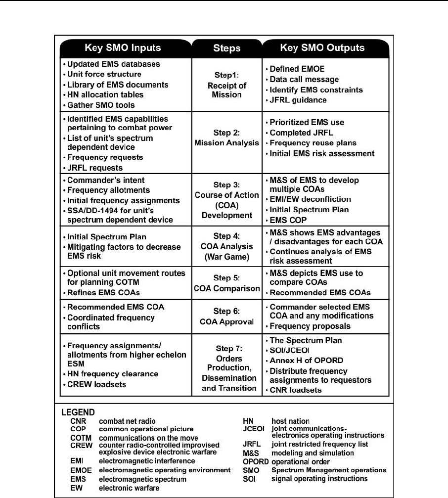
2-24. Key inputs for the MDMP are actions, processes or information spectrum managers provide to the
MDMP. SMO key outputs for MDMP are the completed SOI, reports, frequency proposals or data call
messages. Figure 2-3, on page 2-8, depicts the key SMO inputs and outputs for each step of the MDMP.
Chapter 2
2-8 ATP 6-02.70 31 December 2015
Figure 2-3. Key SMO inputs to the MDMP
SUPPORT TO THE MDMP STEPS
2-25. SMO supports the MDMP through each step of the process. The SMO planning process incorporates
each step of the MDMP in to support the commander. The following are some examples for each step—
Step 1: Receipt of Mission—
Conducting a data call provides a list of SDD and the requirements that those devices need to
perform the mission.
Compiling force structure templates allows the commander to determine the amount and type
of SDD available for the mission.
Modeling the operational area, using SMO tools, with digital topography and electromagnetic
environmental effects information to analyze spectrum supportability.

Tactical Staff Organization and Planning
31 December 2015 ATP 6-02.70 2-9
Determine from governmental and host nation spectrum allocation tables, which frequencies
maybe assigned in a given operational area.
Compiling restrictions or constraints on spectrum use that prevent planning and use of
protected, taboo, and restricted frequencies in the operational area. (see CJCSM 3320-01C,
appendix I, enclosure C for a listing of the worldwide taboo frequencies.
Defining the EMOE provides a common source for spectrum use information, particularly all
available blue (friendly), red (enemy), and grey (neutral and civil) spectrum occupancy.
Step 2: Mission Analysis—
Analyze the EMOE, highlighting unified action partners’ spectrum users, and aid the
commander in determining spectrum priority.
Conducting an initial spectrum risk assessment identifies the spectral impact of a mission on
unified action partners in the operational area. This process also identifies frequency usage
conflicts such as EMI and frequency fratricide.
Generating frequency reuse plans provides for spectrum optimization and increased spectrum
capabilities.
Identifying spectrum constraints where certain frequencies are taboo, such as those not
allocated for use by the host nation.
Determining spectrum capabilities pertaining to combat power, such as EW and counter radio
controlled improvised explosive device electronic warfare systems.
Step 3: Course of Action Development—
Modeling the unit’s boundaries and movement formations, using SMO tools, to develop COA
recommendations.
Performing EMI and EW frequency deconfliction, using SMO tools, for COA development
and spectrum supportability.
Generating frequency allotment and allocation tables for subordinate units.
Identifying the unit’s spectral impact on civilian spectrum users.
Identifying primary, alternate, contingency, and emergency communications for each COA
based on unit capabilities, software simulation, and spectrum supportability.
Step 4: Course of Action Analysis (War Game) —
Depicting the spectrum advantages and disadvantages for each COA.
Identifying mitigating factors for the spectrum risk assessment to reduce or eliminate risks.
Recommending modifications to the COA based on spectrum supportability during the war
game.
Step 5: Course of Action Comparison—
Comparing spectrum use over multiple COAs, using SMO tools, to allow the commander to
determine which COA provides the best flexibility during execution while minimizing risks.
Analyzing routes over a movement of forces determines which route provides the best options
for the commander.
Step 6: Course of Action Approval—
Allows the unit to submit frequency proposals and receive frequency assignments.
Modifying COAs in accordance with commander’s decision.
Coordinating frequency conflicts through higher echelons for mitigation assistance.
Step 7: Orders Production Dissemination, and Transition—
Producing the SOI and joint communications-electronics operating instructions (JCEOI) and
disseminate as needed to units.
Providing input to Annex H (Signal) of the Operations order (OPORD) that addresses all
signal concerns, to include spectrum use information.
Note. Refer to FM 6-0 for additional information on Annex H of the OPORD.

Chapter 2
2-10 ATP 6-02.70 31 December 2015
THE COMMON OPERATIONAL PICTURE
2-26. The common operational picture is a single display of relevant information within a commander’s area
of interest tailored to user requirements and based on common data and information shared by more than one
command. The SMO core functions and common tasks support completion of the COP for the commander.
SMO tools, when used in conjunction with Intelligence and EW Cell information, allow the spectrum
manager to collect spectrum related information tailored to the commander’s operational area. These tools
provide a visually depiction of force structure and geographical locations in a three-dimensional picture that
personnel can understand quickly and easily. The following are some examples of SMO support to the COP—
Live spectrum analysis of a given area of operations: Using SMO planning tools to receive analysis
of the signal, allows the spectrum manager to perform EMI mitigation. A spectrum analyzer or
monitoring receiver, a direction-finding antenna, and analysis software show persistent unplanned
signals that interfere with assigned frequencies. These tools provide a three-dimensional picture
to the commander with a graphical depiction of the spectral footprint of the signal, along with
recommendations for frequency reassignment to maintain communications in the area and the
impacted units. The commander, based on mission priority, deems it necessary to obtain new
frequencies in order to accomplish the mission
Force Movement to a New Location: The commander orders movement to a new location. The
spectrum manager creates the proposed movement route with the SMO planning tool along with
adjacent units’ communications systems, sensors, and receivers. The SMO planning tool performs
a simulation and provides courses of action to determine if the mission command system remains
operational during the movement. The tool calculates that a direct path will cause counter radio-
controlled improvised explosive device EW (CREW) interference on friendly communications
along the route. The tool then presents a report with actionable information such as sources,
victims, levels, and duration of interference. This provides the commander with supplementary
information to make knowledgeable decisions.
31 December 2015 ATP 6-02.70 3-1
Chapter 3
Support to the Warfighting Functions
SMO enables and supports the Army’s warfighting functions described in ADP 3-0,
Unified Land Operations: mission command, intelligence, fires, movement and
maneuver, protection, and sustainment. A warfighting function is a group of tasks and
systems (people, organizations, information, and processes) united by a common
purpose that commanders use to accomplish missions and training objectives. This
chapter links Army SMO to the warfighting functions; it also describes how SMO
supports and enables commander’s efforts as they exercise mission command.
MOVEMENT AND MANEUVER
3-1. The movement and maneuver warfighting function are the related tasks and systems that move forces
to achieve a position of advantage in relation to the enemy. SMO enables movement and maneuver by
maintaining freedom of action within the electromagnetic spectrum. Commanders are able to leverage the
spectrum manager’s advice to provide lethal and non-lethal effects against enemy combat capability,
protection from adversary use of the spectrum. SMO supports movement and maneuver through—
Spectrum resource planning, analysis, and simulation to determine spectrum supportability over a
projected movement of forces.
Analysis, location, and direction finding of unknown and unplanned signals.
Planning and simulating spectral use over the operational area.
Frequency deconfliction planning over a movement.
INTELLIGENCE
3-2. The intelligence warfighting function is the related tasks and systems that facilitate understanding of
the enemy, terrain, and civil considerations. It includes tasks associated with information collection. SMO
supports intelligence through the provision of spectrum situational understanding and the ability to gain a
greater understanding of the EMOE. This understanding occurs through the successful frequency
deconfliction of SDD, greater fidelity in threat recognition, and support to the denial and destruction of
adversary counter-intelligence, counter-surveillance, and counter-reconnaissance systems. SMO supports
intelligence through—
Measurement, analysis, and assessment of spectrum situational awareness.
JRFL production and promulgation to protect intelligence operations.
Centralized databases facilitate planning requirements and assessing collection through
subordinate and adjacent units.
FIRES
3-3. The fires warfighting function is the related tasks and systems that provide collective and coordinated
use of Army indirect fires, air and missile defense, and joint fires through the targeting process (ADRP 3-0).
It includes tasks associated with integrating enemy counter mission command activities. SMO provides
crucial support to the fires warfighting function through the ability to discriminate friendly forces from
adversary targets, increased spectrum awareness, and direct support to EW.
3-4. Electromagnetic environmental effects influence the operational capability of military forces,
equipment, systems, and platforms. Spectrum managers support the fires warfighting function by mitigation
of interference and ensuring systems are compatible. Hazards of electromagnetic radiation to personnel

Chapter 3
3-2 ATP 6-02.70 31 December 2015
(HERP), hazards of electromagnetic radiation to ordnance (HERO), and hazards of electromagnetic radiation
to fuels (HERF), are examples of electromagnetic environmental effects.
3-5. A hazard of electromagnetic radiation to personnel is the potential hazard that exists when
personnel maybe exposed to a radiation field of sufficient intensity to heat the human body. Radar,
communication systems, and EW systems that use high-power transmitters and high-gain antennas represent
a hazard to personnel working on, or near these systems. Leaders should ensure areas are clearly marked off
to avoid injury to personnel.
3-6. A hazard of electromagnetic radiation to ordnance is the danger of accidental activation of electro-
explosive devices or otherwise electrically activating ordnance because of the radio frequency fields. This
unintended actuation could cause premature firing of ordnance.
3-7. A hazard of electromagnetic radiation to fuels is the potential hazard that exists when volatile
combustibles, such as fuel, exposed to radiation fields of sufficient energy may cause ignition. The hazard is
likely to occur when refueling operations are taking place. Leaders must adhere to proper grounding and
static discharge procedures. Cease or minimize transmissions during refueling operations to prevent the
potential hazard and exposure to radiation fields.
3-8. SMO supports fires through—
Coordination of the EMOE to prevent EMI to firing devices, sensors and data links that use the
spectrum.
Coordination with the CEMA element that allows effective use of spectrum resources and EW.
Integration and synchronization of CEMA by assignment and allocation of spectrum use in joint
environments.
Note. Coordinated execution of joint electromagnetic spectrum operations with other lethal and
nonlethal operations that enable freedom of action in the electromagnetic operational environment
comprises electromagnetic spectrum control. (JP 3-13.1)
SUSTAINMENT
3-9. The sustainment warfighting function is the related tasks and systems that provide support and services
to ensure freedom of action, extend operational reach, and prolong endurance. SMO ensures that all spectrum
dependent activities necessary for sustainment function properly and with minimal interference. Further,
through coordination with EW, SMO contributes to overall sustainment in a hostile EMOE. SMO supports
sustainment through—
Design and development, acquisition, and distribution of advanced tools that manage the spectrum
use.
Protection of sustainment forces from friendly and adversary use of spectrum in static or mobile
environments.
Obtaining frequency clearance for all devices for the duration of the mission.
Frequency deconfliction and emissions control procedures in support of sustainment mission
command.
Provides deconfliction within the spectrum to mitigate negative impacts to aircraft survivability.
MISSION COMMAND
3-10. The mission command warfighting function develops and integrates those activities enabling a
commander to balance the art of command and the science of control. Mission command emphasizes the
centrality of the commander. Commanders exercise mission command through the conduct of the operations
process, knowledge management and information management, synchronize information related capabilities,
and through the conduct of CEMA, which includes SMO. SMO enhances mission command in light of other
spectrum dependent activities (such as jamming and passage of intelligence) through effective spectrum
management. In a contested, congested, and competitive EMOE, the mission command function must remain
effective. SMO plays a key part in planning and battle management process and enables situational awareness
Support to the Warfighting Functions
31 December 2015 ATP 6-02.70 3-3
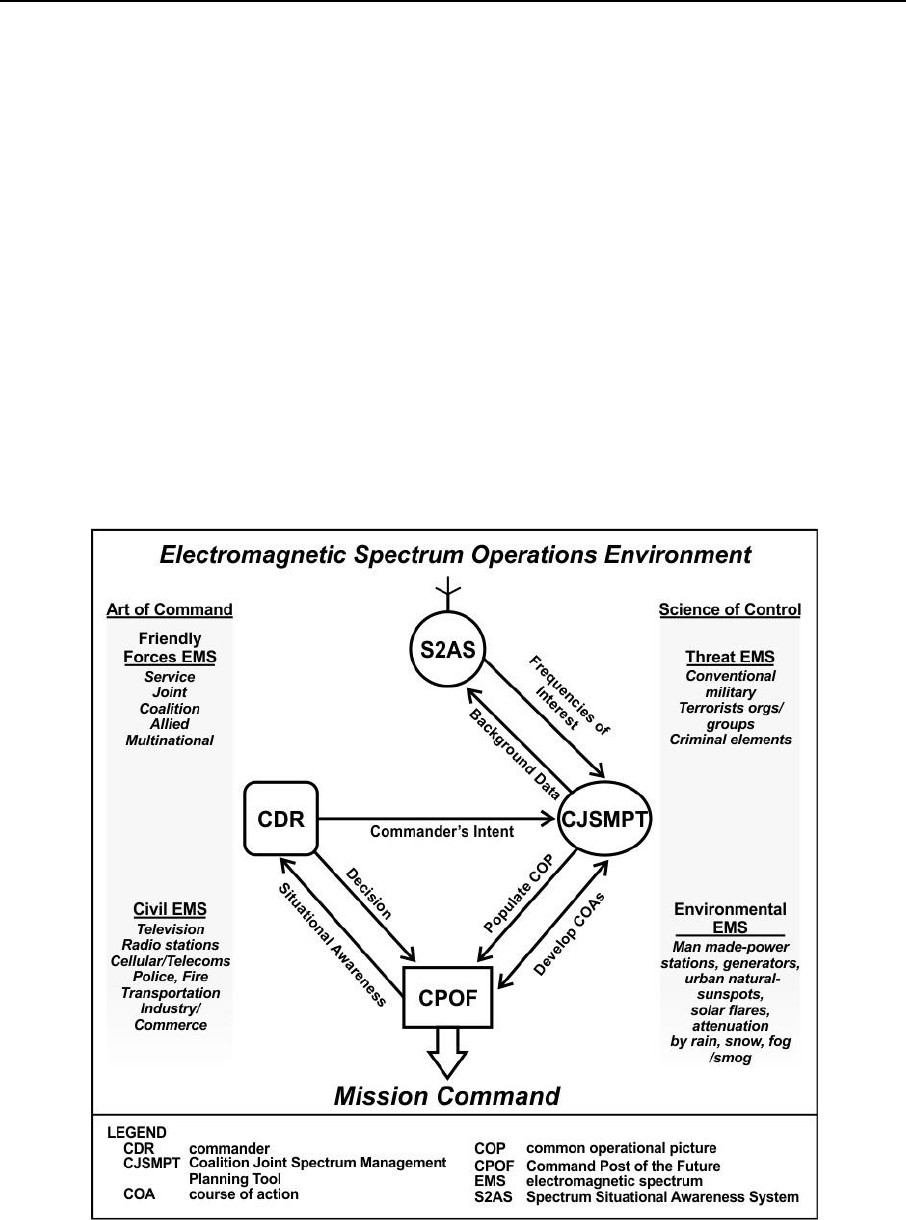
of the EMOE. Spectrum managers are assigned to aviation units to support mission command. Aviation units
require support to flight dispatch elements, and airfield services elements with robust communications
requirements. Figure 3-1 shows the relationship between two SMO tools (described in Chapter 5) that support
mission command. Many SMO tools can be substituted for the two SMO tools depicted in the graphic. These
tools support the commander using the Command Post of the Future.
3-11. SMO supports mission command through—
Planning and preparing the spectrum in response of a mission.
Assessment of the EMOE in response to commander’s intent.
Preparation and maintenance of the EMOE database.
Understanding the impact of a mission on friendly, neutral, adversary, enemy, joint, interagency,
intergovernmental, and multinational entities.
Collecting spectrum information and visualizing this information in quick and easy to understand
formats for completion of the COP.
Control of the spectrum through force tracking and visualization, frequency deconfliction,
reprogramming of SDD, and registration of all spectrum users (such as emitters, sensors, and
receivers) with the spectrum manager.
Development of SMO planning and management tools that support the net-centric environment
(NCE) and become interoperable with Army and joint task force spectrum users.
Figure 3-1. Spectrum situational awareness system and CJSMPT support to mission
command

Chapter 3
3-4 ATP 6-02.70 31 December 2015
PROTECTION
3-12. The protection warfighting function is the related tasks and systems that preserve the force so the
commander can apply maximum combat power. SMO supports the protection warfighting function through
the conduct of frequency deconfliction, interference mitigation, and support to EW defensive actions. SMO
supports protection through—
Network and frequency fratricide avoidance, detection, and mitigation.
Development of the JRFL to prevent frequency fratricide and mission degradation.
Coordination with CEMA Element to protect against blue force EMI during EW operations, such
as counter radio-controlled improvised explosive device EW use.
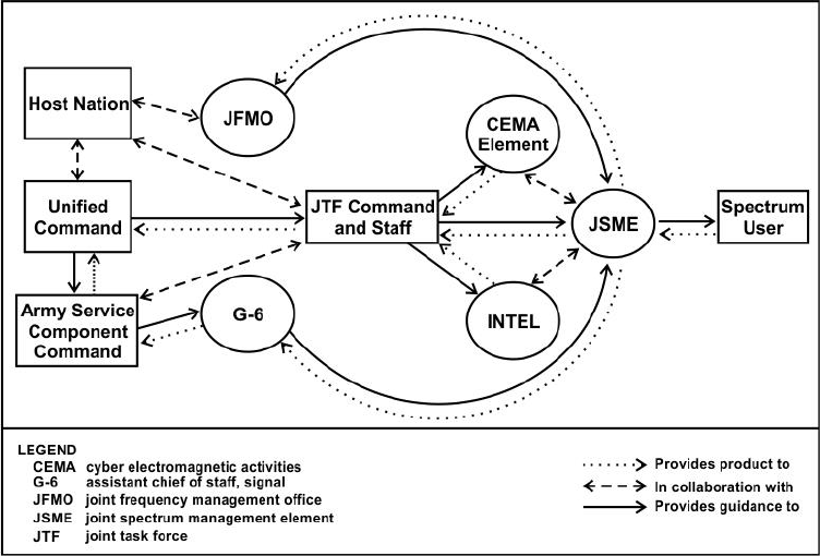
31 December 2015 ATP 6-02.70 4-1
Chapter 4
Joint Task Force Considerations
Modern warfare is inherently a joint operation. Joint operations require precise
coordination and establishment of procedures for effective spectrum use. This chapter
describes the information and products for planning, coordination, and control of the
spectrum at the joint task force level.
INPUTS AND PRODUCTS OF JOINT TASK FORCE SPECTRUM MANAGERS
4-1. Spectrum manager assignments within a joint task force include multiple organizations: JFMO, joint
spectrum management element (JSME), CEMA Element and the G-6. These agencies have a wide variety of
inputs, collaboration, and products. Figure 4-1 shows a visual description of the spectrum management
workflow between organizations in a joint task force environment. The following paragraphs contain an in
depth look at the workflow between organizations in a joint task force environment.
Figure 4-1. Interagency workflow in a joint task force environment
JOINT FREQUENCY MANAGEMENT OFFICE
4-2. The JFMO is a permanent organization within the operational area of a combatant command. The
JFMO Chief is a DA civilian. Various personnel focused on region-specific spectrum requirements, staff the
JFMO. The JFMO staff size varies, and is dependent on regional requirements. Figure 4-2, on page 4-2,
shows the structure of the JFMO.
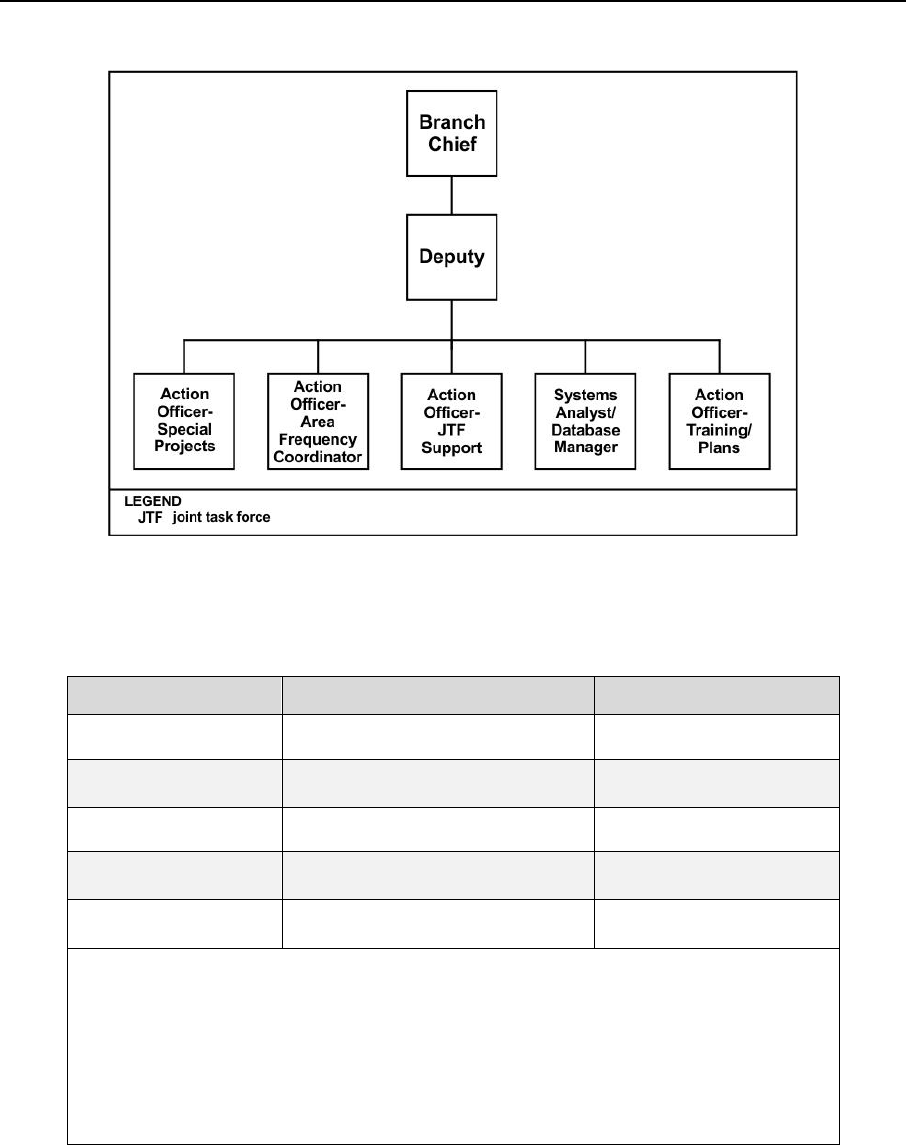
Chapter 4
4-2 ATP 6-02.70 31 December 2015
Figure 4-2. JFMO structure
4-3. Table 4-1 shows the inputs to the JFMO by agency. The table provides the agency, the action conducted
and the input the agency provides.
Table 4-1. Agency inputs to the JFMO
Agency
Action
JFMO Inputs
Combatant Command
Provides guidance and direction
JCEOI
JTF staff, JSME
Provides
Inputs to develop a JTF
JRFL
JSME
Receives
Frequency proposals
Joint staff, civil affairs
(J-5), HN
Provide input and responsible for
Host nation frequency
authorizations
Spectrum users
experiencing EMI
Submit
JSIR report
Legend
EMI electromagnetic interference
JCEOI joint communications-electronics operating instructions
JFMO joint frequency management office
JRFL joint restricted frequency list
JSIR joint spectrum interference resolution
JSME joint spectrum management element
JTF joint task force

Joint Task Force Considerations
31 December 2015 ATP 6-02.70 4-3
4-4. Table 4-2 shows a sample of the products of the JFMO and includes the agency and action taken.
Table 4-2. Products of the JFMO
Agency
Action
JFMO Products
Spectrum users
Provides guidance and
direction
Administrative and technical support for
spectrum use
JTF staff, JSME,
spectrum users
Provides guidance and
direction
JCEOI
JTF staff, JSME
Provides guidance and
direction
The Spectrum Plan, to include frequency
use, reuse, and sharing schemes
JFMO
Provides guidance and
direction
Frequency assignments and allotments
Production and management of
common spectrum use databases
The JRFL, upon approval from Joint
Staff, Operations (J-3)
Mitigation assistance for EMI suffered
Legend
EMI electromagnetic interference
JCEOI joint communications-electronics operating instructions
JFMO joint frequency management office
JRFL joint restricted frequency list
JSIR joint spectrum interference resolution
JSME joint spectrum management element
JTF joint task force
JOINT SPECTRUM MANAGEMENT ELEMENT
4-5. The JSME is a temporary organization that activates only for the duration of a specific joint task force
mission. The JSME is an element within the J-6 and is sometimes an entity within a joint network operations
control center of a joint task force. The senior spectrum manager may lead the JSME from the lead service
of the joint task force. If designated as the joint task force lead, the Army Service component command
headquarters, corps headquarters, or division headquarters G-6 spectrum management office assumes the role
and responsibilities of the JSME.
4-6. Spectrum management personnel from coalition forces and the sister services augment organizations
designated as JSME during deliberate planning using the global force management process. Initial
augmentation during the crisis action-planning phase of operations may come from joint enablers such as the
Joint Spectrum Center (JSC), the Joint Electronic Warfare Center, or directly from the combatant command,
J-6 JFMO. Depending on the size of the force structure supported, JSME end strength ranges from three to
ten military service members.
4-7. The JSME has a primary function to ensure authorized assigned joint task force military forces receive
sufficient use of the spectrum to execute their designated missions. The JSME satisfies spectrum needs and
ensure frequency deconfliction, prior to assignment or allotment, of all SDD including systems used by joint
task force and component forces, such as the United Nations, the North Atlantic Treaty Organization, and
coalition forces. The JSME provides additional support based on strategic agreements between DOD, the
U.S. mission, and the host nation. Table 4-3, on page 4-4, shows the agency inputs to the JSME.

Chapter 4
4-4 ATP 6-02.70 31 December 2015
Table 4-3. Agency inputs to the JSME
Agency
Action
JSME Inputs
JTF commander, JFMO
Provide guidance/
direction
JCEOI Guidance
JTF STAFF
Responsible for
Inter service considerations, such
as data formats, tools in use,
frequency request procedures.
J-6
Provide Guidance /
Direction
Nets to be included on the JCEOI
Component Commanders
Receive Guidance /
Direction from
Friendly Force Spectrum use
requirements and call words for
inclusion on the JCEOI
Joint Staff, Intelligence (J-2)
Responsible for
Priority of intelligence gathering
requirements
Spectrum Users
Provide Input
JRFL requirements
Spectrum Users
Experiencing EMI
Provide Input
JSIR report
JTF Staff and various
databases
Provide Guidance /
Direction for
Spectrum use information on all
friendly military and civilian,
available enemy, and neutral
forces
Spectrum Users
Responsible for
Requests for frequency
authorization, modification, and
deletion
JFMO
Provide Guidance /
Direction for
Frequency allocations
CEMA ELEMENT
Responsible for
Instances of hostile EW
J-3
Provide Guidance /
Direction for
Spectrum user priority
Joint staff, civil affairs (J-5),
Host Nation
Provide
Host Nation spectrum authorization
Legend
CEMA cyber electromagnetic activities
EMI electromagnetic interference
EW electronic warfare
J-2 intelligence directorate of a joint staff; intelligence staff section
J-3 operations directorate of a joint staff
J-6 communications system directorate of a joint staff
JCEOI joint communications-electronics operating instructions
JFMO joint frequency management office
JRFL joint restricted frequency list
JSIR joint spectrum interference resolution
JSME joint spectrum management element
JTF joint task force
Note. Collaboration and coordination with varying agencies, especially host nations, occurs
through a variety of processes. These processes are generally very formal and setup through the
fostering of mutual trust and rapport between the JFMO and host nation. The spectrum manager
must keep in mind customs and cultures, tact and courtesy, and the concerns of other agencies
while still attempting to obtain the amount of spectrum resources necessary for the mission. The
spectrum manager must also maintain accurate records of all dialogue and agreements made with
the host nation.

Joint Task Force Considerations
31 December 2015 ATP 6-02.70 4-5
4-9. Table 4-4 shows some of the products produced by or for the JSME. These products include the data
call message, JCEOI, and the spectrum plan.
Table 4-4. Products of the JSME
JSME Products
Action
Agency
The JRFL, upon approval from
J-3 and JFMO
Provides
Guidance/Direction
Spectrum Users
Data Call Message
Provides
Guidance/Direction
Spectrum Users
JSIR assistance
Provides
Guidance/Direction
Spectrum Users
Annex K of the OPORD, upon JTF
commander approval
Provides
Guidance/Direction
Spectrum Users
JSIR report
Disseminates Product
JFMO
Frequency proposals
Disseminates Product
JFMO
Frequency assignments and allotments for
stationary units and those on-the-move or
at-the-quick- halt
Provides
Guidance/Direction
Spectrum Users
The Spectrum Plan, to include frequency
use and reuse and sharing schemes
In Collaboration With
JTF Staff, Spectrum
Users
JCEOI
Provides
Guidance/Direction
Spectrum Users
Frequency usage conflict identification, risk
assessment, COA recommendations, and
deconfliction
Identified in Collaboration
with
CEMA Element
Definition of EMOE
Identified in Collaboration
with
Joint Staff
Live spectrum monitoring
Disseminated Product
JTF Commander
Legend
CEMA cyber electromagnetic activities
COA course of action
EMOE electromagnetic operational environment
J-3 operations directorate of a joint staff
JCEOI joint communications-electronics operating instructions
JFMO joint frequency management office
JRFL joint restricted frequency list
JSIR joint spectrum interference resolution
JSME joint spectrum management element
JTF joint task force
OPORD operation order
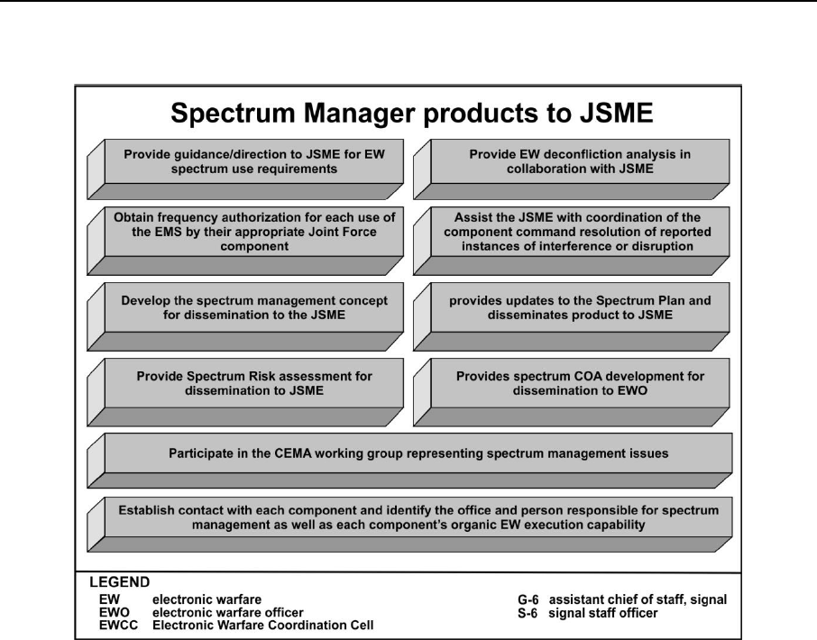
Chapter 4
4-6 ATP 6-02.70 31 December 2015
4-10. Figure 4-4 shows the spectrum manager input to the JSME.
Figure 4-4. Spectrum manager inputs for a JSME
SPECTRUM MANAGEMENT SUPPORT TO DEFENSE SUPPORT OF
CIVIL AUTHORITIES
4-11. Army Defense Support of Civil Authorities (DSCA) encompasses all support provided by the
components of the Army to civil authorities within the U.S. and its possessions and territories. This includes
support provided by the Regular Army, Army Reserve, and Army National Guard when in Title 10 or Title
32 status. United States Code Title 10, Armed Forces, enables the Army to lawfully organize, train, equip,
and conduct operations in coordination with other military services, federal departments, and agencies.
United States Code Title 32, National Guard, consist of National Guard forces conducting DSCA while under
authority of the specific State. Army forces conduct DSCA in response to requests from Federal, state, local,
and tribal authorities for domestic incidents, emergencies, disasters, designated law enforcement support, and
other domestic activities (ADRP 3-28).
4-12. Spectrum management in support of domestic operations requires liaison with state, municipal, local,
and tribal authorities as well as first responders. Spectrum management for domestic operations within the
U.S. must comply with a complex legal, regulatory and policy environment. United States Northern
Command (USNORTHCOM) and United States Pacific Command (USPACOM) are the principal planning
agents for DSCA and have the responsibility to provide joint planning and execution directives for peacetime
assistance rendered by DOD within their assigned areas of responsibility. The other combatant commands
provide capabilities to USNORTHCOM and USPACOM for DSCA as directed by the Secretary of Defense.
4-13. Various resources may provide spectrum management support when Army forces are operating within
the homeland. The separate joint forces headquarters for each state retains responsibility for forces operating
within that state or territory. The National Guard (NG) J-6 spectrum management branch is the office
responsible for coordinating and planning spectrum management for NG forces and provides support to the

Joint Task Force Considerations
31 December 2015 ATP 6-02.70 4-7
State’s spectrum managers for domestic operations. The NG J-6 spectrum management branch provides
coordination between the State’s spectrum managers and all federal agencies. NG J-6 authorizes state
spectrum managers direct liaison with the Army frequency management office or the Army spectrum
management office. Joint forces headquarters state spectrum managers form a JSME in support of operational
task forces under state active duty, dual status (Title 32 or Title 10) domestic operations.
4-14. Activated forces, after acquiring frequency assignments may operate both civil and military systems
within a domestic area of operations to achieve interoperability with other Federal agencies and civil
authorities. NG forces may request frequency assignments through the NG, or through Title 10 military
channels depending on their duty status for a given operation. The National Telecommunications and
Information Administration control the spectrum within the homeland. They certify and license civilian usage
of the electromagnetic spectrum. NG forces and U.S. Coast Guard may operate both civil and military
systems within a domestic area of operations, as well as numerous states, local and federal agencies.
4-15. After receiving orders to conduct movement for a domestic operation, each operational element
initially contacts their local state spectrum manager or JSME for a JCEOI extract detailing the frequencies
and procedures to use for communications. The local spectrum manager or the JSME submit a standard
frequency action format (SFAF) request for frequencies on behalf of the end user. A state’s qualified
spectrum manager provides spectrum management for a given geographical state to the greatest extent
possible. Spectrum managers coordinate for interstate operations, and for spectrum deconfliction for
operations adjacent to another spectrum manager’s area of responsibility. Local spectrum managers form the
JSME and work directly for the incident commander (or the local state joint force headquarters prior to the
appointment of an incident commander).
4-16. Domestic operations lessons learned have demonstrated that both unity of effort and coordinated
spectrum management are critical to the success of the operation. Congress and the DOD, through the
implementation of a dual status commander (commander of both Title 32 NG forces, and Title 10 NG and
active Army forces for a domestic operation) have addressed unity of effort. Unity of command is not
applicable between Federal military forces and the state NG, but unity of effort can be achieved if the
President and the Governor formally agree to appoint a dual-status commander. Federal authorities have been
established that allow a designated dual-status commander to serve in a hybrid Federal and state status. A
dual-status commander will usually be a National Guard officer who is given simultaneous but separate
authorities over Federal and state military forces. Spectrum management for a domestic operation requires
consolidation under one JSME, (or at a minimum coordinated Title 10 and Title 32 JSMEs led by the same
commander) to minimize confusion and provide seamless support to tactical communications.
4-17. The JSME initially assigned to an incident continues to work for the incident commander as the
operation transitions to a different duty status or legal authority, to ensure continuity of spectrum
management. Typically, a state Governor or Adjutant General creates a standing joint task force including a
JSME, or establish a joint task force with a JSME in response to an incident. Optionally, each state builds its
JSME from qualified spectrum managers, and equipment from within the state National Guard’s tables of
distribution and allowance allotment. Should a state not have qualified spectrum managers, the Adjutant
General and Governor may request qualified spectrum managers prepare to deploy from other states to form
a JSME under a formalized emergency management assistance compact. The JSME may request a spectrum
flyaway team from the NG bureau J-6 and USNORTHCOM to supplement the element.
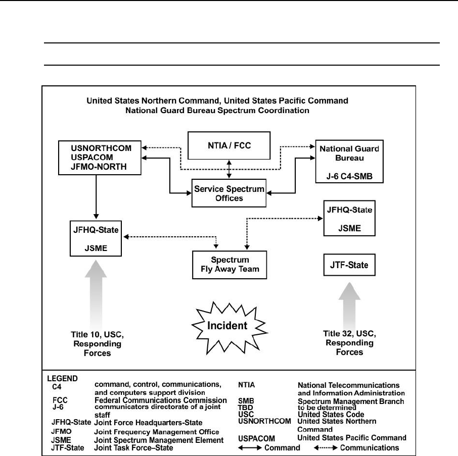
Chapter 4
4-8 ATP 6-02.70 31 December 2015
4-18. Figure 4-5, provides a graphic of the collaboration process during domestic operations.
Note. See JP 3-28 and JP 6-01 for more information regarding domestic operations.
Figure 4-5. Spectrum management support during domestic operations
31 December 2015 ATP 6-02.70 5-1
Chapter 5
Spectrum Management Operations Tools
Spectrum managers have access to a wide variety of tools to aid in effective and
efficient spectrum planning and management. This chapter provides a technical
description of several tools used to facilitate spectrum management operations.
Included in this chapter are hardware and infrastructure requirements, software used,
and capabilities of spectrum management tools.
TOOL CONSIDERATIONS
5-1. There are a variety of spectrum related tools used to plan and manage communications networks and
SDDs. Many of these tools do specific functions of limited scope precluding the sharing of relevant
information among these functions creating inefficiencies. This can lead to erroneous planning and
assignments that can cause frequency interference. It is essential for the benefit of all spectrum stakeholders,
tools should share data in a consistent manner to improve efficiencies. As an example, EW operators should
use the same tool that the spectrum manager uses in order to allow the spectrum manager to mitigate harmful
interference to friendly systems possibly caused by EW systems.
5-2. Gathering and managing spectrum data requires considerable time in order to ensure accuracy. Tools
that support the automation of spectrum management functions can drastically reduce this time constraint.
Tools that promote the flow of information between spectrum stakeholders reduce the planning cycle leading
to quicker decisions. Spectrum managers are able to perform the core SMO functions much more efficiently
when tools comply with the net-centric environment.
5-3. The NCE, a common shared virtual space used within and among differing authenticated units and
organizations, has facilitated numerous advantages for spectrum managers of all levels. Central access to
multiple databases reduces or eliminates the need to visit agencies to obtain a list of devices used in the area
of operations. Having central databases requires SMO tools to have interoperable and compatible formats in
order to function. The net-centric environment is very effective in joint task force operations.
5-4. There exist many data file standards regarding frequency proposals. Standard Frequency Action
Format (SFAF) is a line oriented text format used by DOD, and by U.S. allies and unified action partners
who use Spectrum XXI. SFAF is the standard format for frequency proposals, assignments, modifications,
renewals, reviews, and deletions.
SPECTRUM SITUATIONAL AWARENESS SYSTEM
5-5. The Spectrum Situational Awareness System (S2AS) is theater provided equipment used to assist in
maintaining effective use of the spectrum. The S2AS provides fixed site and portable spectrum-monitoring
receiver that performs instantaneous analysis of captured spectrum data. The S2AS consists of government
off-the-shelf software referred to as multi spectral ambient noise collection and analysis tool (MANCAT)
and commercial off-the-shelf hardware Rohde & Schwarz PR100 monitoring receiver and ancillary antennas.
The S2AS requires the unit to provide a computer to run the software and a global position location device.
The system comes with a ruggedized carrying case that protects the PR100 and HE-300 antenna while in
transit. Figure 5-1, on page 5-2, shows the components that comprises S2AS.
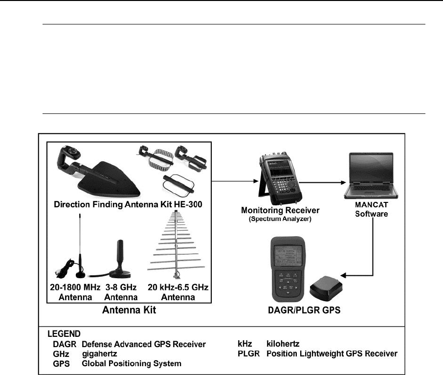
Chapter 5
5-2 ATP 6-02.70 31 December 2015
Note. An upgrade to the HE-300 antenna is available that includes a built in global positioning
system location device and electronic compass. This capability, in conjunction with an available
software update for the PR100, allows for rudimentary direction finding of signals and
triangulation between multiple S2AS users and measurements. The S2AS provides direction-
finding antenna and triangulation capability intended for post, camp, or forward operation base
locations. System use of S2AS is for a relatively small area. This upgrade also eliminates the need
for a unit provided global positioning system receiver.
Figure 5-1. S2AS and supporting equipment
5-6. The advantages of a monitoring receiver over a traditional spectrum analyzer are its rapid precision
measurements and analysis of spectrum over a wide bandwidth. The monitoring receiver provides the
measured spectrum to the MANCAT software for automated analysis. The PR100 can operate on 100 to 240
volts alternating current and comes with a wide variety of connectors to allow for connecting to differing
voltage sources around the world. The PR100 also has an easily removable and rechargeable battery with an
approximate lifespan of 3.5 hours.
5-7. When used with a location device, S2AS allows for mobile measurements of the spectrum. For
example, the spectrum manager can take S2AS on a convoy route to measure persistent signals that are in
use in the area. The location device senses the grid coordinates of the route for mapping captured signals by
other tools (Global Electromagnetic Spectrum Information System [GEMSIS] and MANCAT). When
imported, Google maps provide the software overlays with a color-coded spectrum map over a three-
dimensional digitally mapped terrain to support the COP. Figure 5-2, on page 5-3, depicts Soldiers operating
the direction-finding antenna and the PR-100 handheld receiver.
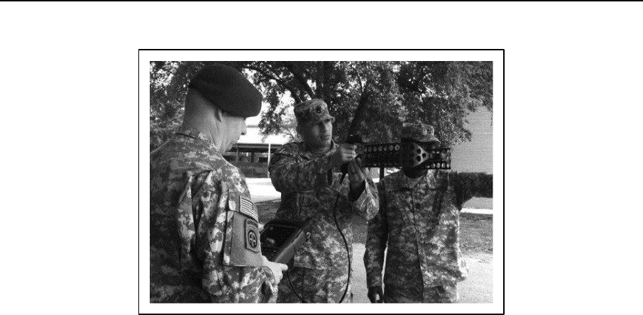
Spectrum Management Operations Tools
31 December 2015 ATP 6-02.70 5-3
Figure 5-2. S2AS in use by Soldiers
5-8. The S2AS provides a fast panoramic scan across the frequency range of 9 kHz to 7.5 GHz. This enables
Soldiers to quickly access the spectrum and begin to incorporate data into the required database. The display
on the device provides a spectrum and spectrogram display which users of the spectrum analyzer may be
familiar with on a portable 6.5" color screen. The unit provides storage of measurement data to the receiver's
built-in storage card. The PR-100 design is ergonomic and rugged for portable use and low weight. The
device has a setting for manual location of spectrum emissions using the active directional antenna or
automatic location of spectrum emissions with direction finding algorithms.
5-9. The operator of the S2AS can save spectrum measurements in comma-separated value format and
spectrum screenshots in portable network graphics format. MANCAT software exports reports in PDF,
HTML, JPEG, or TIFF formats.
5-10. The S2AS includes a continuous band antenna that is vehicle mounted or fixed to a tripod stand for
measurements of spectrum from 30 to 6000 MHz. The system includes a handheld HE-300 antenna with
three interchangeable modules for the 20 MHz to 7.5 GHz ranges and the HE-300HF module for high
frequency ranges from 9 kHz to 20 MHz. Antenna HE-300 provides the capability to perform direction
finding of unplanned signals in specific frequency ranges. S2AS is compatible with some antennas that units
may already have, including the SINCGARS vehicle whip and the OE-254 antenna.
5-11. The S2AS standard package can measure and analyze signals from 20 MHz to 7.5 GHz with the
included continuous band antenna and HE-300 antennas. This range encompasses the majority of spectrum
conflicts the spectrum manager encounters. An upgrade package, that expands the range to 18 GHz, is
available for users that need to analyze higher frequencies, but cost is an issue for users that do not regularly
analyze those frequencies.
5-12. S2AS uses standard data formats compatible with CJSMPT, GEMSIS and Spectrum XXI. Once the
captured signals are available in the CJSMPT or Spectrum XXI tools, the spectrum manager can update
known databases. The MANCAT software allows the user to import frequencies of interest from planned
databases, such as Spectrum XXI, and provide a visual display to the operator of planned or known signals.
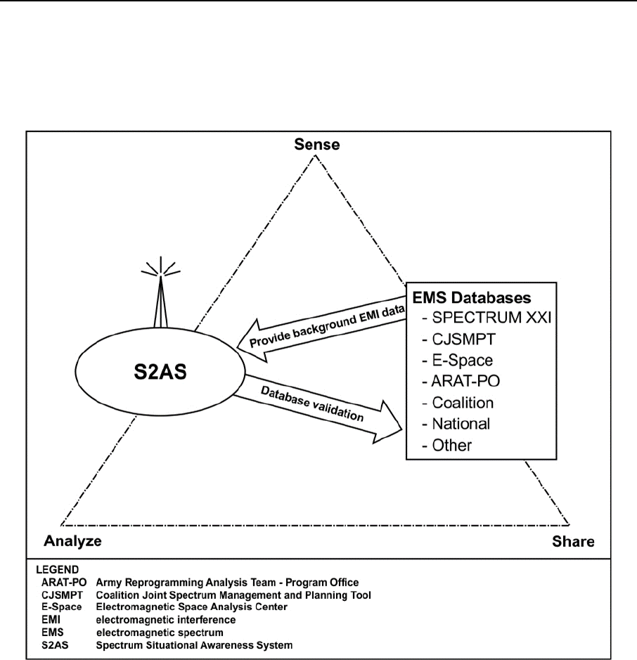
Chapter 5
5-4 ATP 6-02.70 31 December 2015
5-13. S2AS visually differentiates signals that are not in any planned database so that the spectrum manager
can further investigate the source of the signal. Figure 5-3 shows the functional relationship between the
S2AS key capabilities. The figure provides a graphical depiction of the sense characteristic. Sensing and
monitoring frequencies that are available to the user is an initial operational function of the S2AS. The system
then analyzes the information captured and shares the data with the listed database.
Figure 5-3. S2A2 functional relationships
GLOBAL ELECTROMAGNETIC SPECTRUM INFORMATION SYSTEM
5-14. Global Electromagnetic Spectrum Information System (GEMSIS) is a joint program of record that
provides access to several spectrum management tools. Spectrum managers access GEMSIS on the internet
via NIPRNET and SIPRNET connections. GEMSIS increases the effectiveness of the COP, accelerates
spectrum access, increases interoperability, and support to NCE. GEMSIS increment 2 incorporates other
SMO tools, such as CJSMPT, Spectrum XXI-Online, systems planning, engineering, and evaluation device
(SPEED), and Afloat Electromagnetic Spectrum Operations Program (AESOP) as an effort to further
transition spectrum management to a NCE compliant and provide all the needed capabilities to the spectrum
manager in one central tool.
5-15. GEMSIS provides worldwide visibility of host nation supportability of SDD equipment. The system
automates distribution of host nation coordination requests and Combatant command submission of host
nation supportability comments. This enables spectrum managers to determine the historical supportability
of other systems in the same frequency band.

Spectrum Management Operations Tools
31 December 2015 ATP 6-02.70 5-5
COALITION JOINT SPECTRUM MANAGEMENT PLANNING TOOL
5-16. Coalition Joint Spectrum Management Planning Tool (CJSMPT) is a capability delivered by the
GEMSIS program. CJSMPT developed as a joint capability technology demonstration that integrates
spectrum management, modeling, simulation, and planning tools that enables spectrum managers at all levels
(joint task force and below) to perform spectrum planning and frequency deconfliction for mission planning
and combat operations.
5-17. CJSMPT provides the capability to predict interference as units move across a simulated EMOE.
CJSMPT uses this simulation to perform deconfliction analysis that is compatible with EW operations and
future rapid maneuvering forces. This means that the spectrum manager can simulate and visualize a unit’s
movement, perform spectrum interference analysis and frequency deconfliction, and provide
recommendations to the commander for complete spectrum use during the movement.
5-18. The CJSMPT database is the spectrum knowledge repository. CJSMPT is compatible with S2AS and
Spectrum XXI using common data formats. The map manager functional area of the software allows the user
to import any national geospatial-intelligence agency map resource. The spectrum data repository provides
users with a single authoritative data source of known databases, such as joint, equipment, tactical, and space.
5-19. CJSMPT performs spectrum optimization and conflict mitigation using environmental factors,
operational priorities, frequency allocation and assignments, and international spectrum management policies
and regulations. The main visualizer panel within CJSMPT displays spectrum use in a color-coded two and
three dimensional picture that is available throughout the mission’s duration. CJSMPT enables the spectrum
manager to provide the commander with accurate spectrum information for civil (grey), hostile (red), friendly
(blue) and counter radio-controlled improvised explosive device EW, referred to as CREW, and Intelligence
operations on blue force SDDs.
5-20. CJSMPT allows the operator to submit frequency proposals to the Spectrum XXI system using the
SFAF and standard spectrum resource format compliant formats. Upon approval by Spectrum XXI, CJSMPT
can import frequency assignments into the spectrum knowledge repository. CJSMPT can automatically
format a satellite access authorization into the appropriate format (SFAF) saving the spectrum manager time.
5-21. The spectrum requirements advisor utility within CJSMPT automatically generates spectrum reuse
plans and calculates the minimum spectrum requirements for an interference free operation over a given
movement of forces. This allows for rapid force movement while minimizing the spectral impact of a mission.
CJSMPT can generate formatted reports, such as the joint spectrum interference resolution (JSIR) report,
based on the communications effects simulator utility. The operator can save detailed reports in extensible
markup language (XML), HTML, or comma separated values formats. Spectrum planning within CJSMPT
can account for bandwidth, frequency locking, guard bands, and frequency allocation tables.
5-22. CJSMPT allows the spectrum manager to develop scenarios quickly by placing forces into the database
using force templates. Force templates within CJSMPT include force structure, SDDs characteristics, and
spectrum usage information for devices that have passed the spectrum certification process. CJSMPT allows
the user to place device characteristics into the database for devices that have not received spectrum
certification. Without this capability, the spectrum manager must manually place force structure and SDD
characteristics into a variety of locations, such as XML spreadsheets. Manual input can cause data format
inconsistencies, possible human error, and time delays.
5-23. CJSMPT functions in a NCE by granting network access through SIPRNET. Users perform peer-to-
peer collaboration and retrieve information from the master spectrum knowledge repository while connected
to the SIPRNET. CJSMPT also provides support to joint task force environments by providing features
targeted to key joint task force agencies. JFMO and JSME agencies develop and maintain the JRFL and
JCEOI, which resides over the spectrum knowledge repository database for the area of responsibility.
Spectrum managers assigned to the JFMO or JSME control and update the spectrum knowledge repository
with specific locally operated equipment and identify the effects of EW on emitter devices.
5-24. The CJSMPT administrator, serves as the overall oversight of the CJSMPT database by maintaining
force structure and equipment, control of the master spectrum knowledge repository, and updating a detailed

Chapter 5
5-6 ATP 6-02.70 31 December 2015
list of known SDD worldwide. CJSMPT functions in a standalone environment to operate while not
connected to the SIPRNET.
SYSTEMS PLANNING, ENGINEERING, AND EVALUATION DEVICE
5-25. The systems planning, engineering, and evaluation device (SPEED), developed as United States
Marine Corps government off the shelf software. SPEED is a modular software application that provides
modules that target user specific needs. SPEED allows the spectrum manager to complete and edit SFAF
forms while using an equipment database that includes tactical platforms, equipment, and antennas. The
Asset Manager module within SPEED provides the capability to import, export, build vehicle manifests,
personnel rosters, and equipment deployment lists. SPEED is free to all federal agencies but primarily used
by the United States Marine Corp communications and spectrum managers. Army spectrum managers may
interface with SPEED in joint operations.
5-26. SPEED provides both two and three-dimensional views of the operational area to support the COP.
The Advanced Prophet and Terrain Integrated Rough Earth Model and National Geospatial Intelligence
Agency provide map data to the system. SPEED provides the user with a color-coded display of spectrum
use over the operational area. SPEED can generate JRFL input in the correct format to the next higher
echelon. The system allows the user to manually input, store, and view information for a tactical satellite
network defined in a satellite access authorization, but cannot automatically format the authorization into the
SFAF or standard spectrum resource format (SSRF). SPEED is a software package that is distributed with
the automated communications engineering software or joint automated CEOI system image on the unit
provided AN/GYK-33 computer.
AFLOAT ELECTROMAGNETIC SPECTRUM OPERATIONS PROGRAM
5-27. AESOP is an integrated operational radar, combat system, and communications frequency-planning
tool primarily used by U.S. Navy and U.S. Coast Guard spectrum managers. This tool calculates optimal
frequency use and distance separation that considers all strike group SDDs. AESOP minimizes
electromagnetic interference in accordance with national and international frequency regulations. The strike
group staff or designated frequency coordinator can select frequencies and separation distances for the
group’s ships to ensure that the radars operate with a minimum of electromagnetic interference.
5-28. In addition to the ships of the U.S. Navy, AESOP contains data from fleets of over 60 countries.
AESOP supports radar and communication analysis and spectrum planning for joint warfare operations on
platforms for the following—
Ships.
Submarines.
Aircraft.
Military and civilian ground sites.
5-29. AESOP periodic updates have improved the performance of communications networks in the presence
of counter radio-controlled improvised explosive device electronic warfare and other EW. The AESOP
master database is shore based and is only available via connection to the SIPRNET. For users with no access
to SIPRNET or having limited bandwidth, AESOP is available in a standalone mode with a local database.
5-30. AESOP is compliant with the SFAF and SSRF. Measurements taken by AESOP provide input and
development of the DD Form 1494. AESOP provides spectrum visualization after analysis of spectrum use.
AESOP can import and export XML files. The system can provide the Navy’s input to the JRFL during joint
task force operations. Army spectrum managers may interface with AESOP when coordinating spectrum use
in operational areas collocated with Navy missions.
SPECTRUM XXI
5-31. Commanders have several configuration options within Spectrum XXI. Spectrum XXI is a client and
server, Windows-based software system that provides spectrum managers with a single information system
that addresses spectrum management automation requirements. The JSC manages Spectrum XXI. Spectrum
XXI supports operational planning as well as near instantaneous management of the electromagnetic

Spectrum Management Operations Tools
31 December 2015 ATP 6-02.70 5-7
spectrum with an emphasis on assigning compatible frequencies and performing spectrum-engineering tasks.
Spectrum XXI client version is a software package that requires a unit funded computer.
5-32. The joint spectrum center central repository for Spectrum XXI provides the DOD with a central
database that contains spectrum certification for compliant systems, topography and electromagnetic
environmental effects data, and all DOD spectrum proposals and assignments. The repository also serves as
the mechanism to transfer data between the DOD and NTIA for permanent frequency assignments in the U.S.
and its possessions. Spectrum XXI users may access the government master file through the central repository
as needed.
5-33. Spectrum XXI users can connect to one of the three regional servers through local area network access,
SIPRNET access, or secure telephone for dial-up access. The Spectrum XXI database uses the Oracle
database management system based on structured query language that requires licenses and training for the
regional servers. The client version that Army spectrum managers use does not require an Oracle license or
training. The client can function in standalone mode using the local database with limited functionality when
network connectivity is unavailable. Spectrum XXI contains a table of International Telecommunications
Union allocations by region to aid the spectrum manager in international spectrum planning compliance. The
Spectrum XXI database also contains geographical boundaries and utilities. The system can plot SDD based
on frequency records.
5-34. Spectrum XXI allows the user to create and maintain permanent, temporary, proposed assignments,
including background on frequency assignments. Spectrum XXI analyzes frequency assignments for
operating conditions, interference, intermodulation, allocation and allotment tables, and compliance with
technical and administration standards. A simulated spectrum analyzer provides a display of current spectrum
occupancy and projected spectrum use at user-defined sites.
5-35. Spectrum XXI allows for the creation of the JSIR to aid in the mitigation of EMI. The system also
creates and manages input to the JRFL. Spectrum XXI can analyze the impact of EW on spectrum users.
Spectrum XXI is compliant with the SFAF as outlined in the MCEB Publication 7 format.
Spectrum XXI Key Components
5-36. This section provides readers with information on the various components of the Spectrum XXI
software. The modules described in this section are a small sample of the capabilities of what Spectrum XXI
provides to commanders and leaders.
5-37. Interference Analysis Module analyzes existing frequency assignments for potential interference.
This analysis, is normally performed when the holder of a frequency assignment reports interference from an
unknown station. An interference analysis maybe accomplished to determine whether a transmitter on a
single frequency would potentially cause interference to an existing environmental receiver represented by a
frequency record in the database. The interference analysis module performs analysis to determine if a
receiver potentially receives interference from an existing environmental transmitter represented by a
frequency record in the database.
5-38. Interference Report Module generates interference reports that describe interference problems and
provides information to resolve the problem. Interference reports can also document a history of problems,
and thus identify possible causes for subsequent interference. If interference problems exist, the first step as
a spectrum manager is to verify that the person reporting the interference has authorization to use that
frequency. Spectrum managers attempt to resolve interference problems at the lowest level possible. If this
is not possible, create a report for distribution to higher authorities. If a resolution is not found, the
interference information is reported to the unified or specified command (usually the combatant commander
or the service representative) who then may call upon the JSIR team (as part of the JSIR program located at
the JSC) to investigate.
5-39. EW Deconfliction Module assesses the impact of a planned electronic attack and jamming on existing
receivers during contingency operations and exercises. The joint staff, operations must know the operational
situation to make intelligent decisions when using this module. The EW Deconfliction Module, used in
conjunction with the JRFL Module, documents a list of frequencies protected from jamming. In addition, the
module analyzes the impact a frequency jammer has on environmental receivers using a range of azimuths.
Analysis results comprise three types of conflicts—

Chapter 5
5-8 ATP 6-02.70 31 December 2015
Frequency assignment conflicts.
JRFL conflicts.
Communications-Electronics Operating Instructions conflicts.
5-40. The Joint Restricted Frequency List Module is a management tool used by various operational and
support elements to identify the level of protection they desire, applied to specific spectrum, to preclude these
assets from being "jammed" by friendly forces conducting electronic warfare activities. The JRFL
identification and building process begins at the unit level, works upward through the military services' chain
of command, then consolidated within the combatant command or joint task force staff. The module allows
users to select frequency assignment from Spectrum XXI or JCEOI nets. Selecting these frequency
assignments is done by importing the generated CEOI in the JRFL module.
5-41. The Engineering Tools Module is a collection of utilities used to perform several types of analyses—
Coordinate Conversion: This utility provides a graphical representation of the conversion
between latitude, longitude, and military grid coordinates.
Co-site Analysis: Used to perform co-site analysis on a list of frequencies and emissions.
Coverage Plots: Used to create terrain elevation plots, line-of-sight plots, and signal strength
plots. This function provides the commander analytics help determine the best placement of
sensors.
Geomagnetic Conversion: The Geomagnetic Conversion utility converts magnetic azimuths to
true azimuths.
High Frequency Skywave Analysis: The High Frequency Skywave Analysis utility in calculates
the high frequency skywave, propagation prediction values for the maximum usable frequency,
the frequency of optimum transmission, and the lowest usable frequency based on the time of day
between a transmitting and receiving location.
Point-to-Point Link Analysis: The Point-to-Point utility displays the terrain profile and aids in
determination of the viability of radio links between transmitting and receiving locations.
Satellite Look Angles for Multiple Earth Stations and Multiple Satellites: Used to calculate
the azimuth and take-off (elevation) angle from earth stations to geostationary satellites.
Spectrum Occupancy: Used to display a graphical representation of the calculated received signal
power at a specified location indicated in the frequency records of the assignment database (this
is similar to the view seen on a spectrum analyzer).
5-42. The Topographic Manager Module is an automated capability that reformats the level-1and level-2
digital terrain elevation data obtained directly from the National Geospatial-Intelligence Agency on compact
disk-read only memory disks. The Topographic Manager can register and manage reformatted topographical
data files.
5-43. The Frequency Assignment Module automates the processing of requests for the use of frequency
resources from spectrum managers in support of authorized users. The process includes the preparation of
frequency assignment proposals, validation of those proposals, determination of possible interference with
the background environment, distribution and status tracking of proposals. The Frequency Assignment
module also provides processes for frequency assignment database updates and retrievals.
5-44. The Allotment Plan Generator Module creates a list of frequencies commonly referred to as
Allotment Plans, Channelization Plans, Spectrum Use Plans, or Radio Frequency Authorizations. These plans
are a frequency resource for nominating proposals using the Frequency Assignment module. In some cases,
allotment plans disseminate authorized temporary frequencies used for training or tactical exercises.
5-45. The Compliance Module checks the format and content of frequency records saved to a file and are
not in the proposal editor. Three types of compliance checks maybe performed: allocation table checks,
Canadian and Mexican coordination checks, or field validation checks. You also have the option to perform
all checks. The record source for your records determines which validation checks are performed.
International users should use the Validation option only.
5-46. Spectrum Certification System is an automated system used to prepare a DD Form 1494, Application
for Equipment Frequency Allocation, at frequency management offices that support materiel acquisition.

Spectrum Management Operations Tools
31 December 2015 ATP 6-02.70 5-9
5-47. The Data Exchange Module electronically exchanges data between servers and client computers. The
Data Exchange Module manages the server accounts, job accounts, and domains used for data exchanges. A
stand-alone client (not network connected) cannot use the functions of Data Exchange. When first installed,
Spectrum XXI is a stand-alone client until the initial connection to a server. When connected it becomes a
data-exchanging client.
HOST NATION SPECTRUM WORLDWIDE DATABASE ONLINE
5-48. The Host Nation Spectrum Worldwide Database Online (HNSWDO) is a web application that
facilitates warfighter deployment and communications by providing worldwide visibility of host
supportability of SDD. The HNSWDO automates the distribution of host nation coordination requests
allowing combatant command submission for host nation supportability, reducing time requirements for
managing the host nation spectrum authorization process. The design of the database provides informed
decision making concerning frequency bands. This mitigates the risk of acquiring potentially unsupportable
systems. HNSWDO provides the user with near instantaneous updates and dramatic reductions in process
lag (from years to months). HNSWDO requires an approved account and NIPRNET access using a unit
provided laptop computer. The Defense Spectrum Organization processes account request.
Note. Host nation allocation tables and SDD certification does not constitute the authorization to
assign frequencies within the host nation. Send all formal frequency requests to the host nation to
obtain frequency authorization. See JP 6-01 for more information on host nation coordination.
AUTOMATED COMMUNICATIONS ENGINEERING SOFTWARE AND JOINT AUTOMATED
COMMUNICATIONS ENGINEERING SOFTWARE
5-49. Automated Communications Engineering Software (ACES) and Joint Automated Communications
Engineering Software (JACS) are part of the Army key management system that automates the management
of communications security (COMSEC) keys, electronic protection (EP) data, and SOI. These multipurpose
programs reside on a laptop computer. Key features of the software for SMO purposes are SOI generation,
viewing and printing, EP identifiers, transmission security keys, data generation, creating loadsets for
SINCGARS and SINCGARS compatible radios and electronic distribution of the joint automated
communications-electronics operation instructions system.
5-50. ACES and JACS integrate secure network planning, EP distribution, and SOI generation and
management. The workstation functions in conjunction with the data transfer device, hosting tier 3 software,
to automate cryptographic control operation for networks with electronically keyed COMSEC equipment.
5-51. The resident software components on the ACES or JACS workstation include the following—
General purpose module.
Core module.
Area common user system module.
Resource manager module.
Master net list module.
Signal operating instructions (SOI) module.
Combat net radio module.
ARC-220 Module
Satellite Communications Module
General Purpose Module
5-52. The general-purpose module provides the information and operations necessary to satisfy the planning
requirements for cryptonets that operate independently of area common user systems and combat net radio
networks. It allows the planning capability for manual key assignments for compatible COMSEC equipment
in an operator-designed cryptonet configuration. It allows for the importing of the Black Key packages from
the local COMSEC management system.

Chapter 5
5-10 ATP 6-02.70 31 December 2015
Area Common User System Module
5-53. The area common user system module lists information that encompasses both Joint Network Node
equipment and echelons above corps networks. The module contains procedures for creating and drawing an
area common user system backbone network and creating and drawing network extensions. It also describes
the procedures required to validate and generate area common user system networks, and modify area
common user system member properties.
Resource Manager Module
5-54. The resource manager module contains the list of available frequency resources and allows creation,
editing, merging, deleting, and printing of these resources. Each frequency resource is described by attributes
that specify the authorized use and location of all the frequencies contained within the resource. The resource
module also provides planners the capability to import and export resources in JACS, Integrated System
Control, and SFAF formats.
Master Net List Module
5-55. The master net list module provides a communications list containing the net name or description, net
identification, organizational code, restrictions, frequency type, power, reuse class, reuse zone, and call word
or color word requirements. The master net list is developed for an operations plan. The master net list module
provides the capability to create, edit, merge, delete, and print nets. The master net list module incorporates
a number of SFAF-compatible fields to facilitate the transfer of data to and from other frequency management
systems such as Spectrum XXI, as well as service unique systems. The database capabilities of the
workstation allow the data in the master net list to create the initial SFAF frequency proposal and the SOI.
SOI Module
5-56. The SOI module contains call signs, call words, frequency assignments, signs and countersigns. The
SOI module also contains pyrotechnic and smoke signals, dictionaries, groups, quick reference, and title
pages. Generation of pyrotechnics and smoke signal components may be separate or randomly selected. SOI
also provides the capability to create the Master Call Sign packets, as well as separate extract packets, while
maintaining a database link to nets in the master net list.
Combat Net Radio Module
5-57. The combat net radio module provides the necessary functions to create, modify, and generate hopsets
or loadsets for SINCGARS transmission security keys. It also provides the capability to plan combat net
radio nets in all bands. Combat net radio network planning provides integration with the master net list
module. Loadsets are packages of frequency hopping data and COMSEC keys required to load up to six
channels of the SINCGARS radios. One loadset consists of COMSEC keys tags, hopsets, lockouts,
transmission security keys and net identifiers. Hopsets consists of a set or sets of resources converted into
SINCGARS useable frequency hopping data. The complexity of the hopset may be directly related to the
amount of memory needed in the receiver-transmitter. Hopset resources maybe constructed with minimal
pattern interruption, as the radio is frequency hopping at a rate of 100 channels per second. Lockouts are
digitized hopset data generated and stored in the combat net radio. Lockouts electronically map all available
frequencies by relaying to the radio’s memory frequencies it cannot use. This deliberately disables unused
frequency channels, avoiding interference with another service.
ARC–220 Module
5-58. The ARC–220 module allows platforms and equipment assignment to ARC–220 nets. ARC-220 is a
radio network that supports long-range communications between military aircraft and ground stations. This
network type provides support for the AN/ARC-220 (aircraft version) and AN/VRC-100 (ground version)
radios. These radios operate in three different modes: single channel (Basic Preset or Manual), automatic link
establishment, and electronic counter-counter measure. The net validate function ensures that the platforms
intended to communicate with each other can in fact do so with the equipment they have been allocated. The
net generated function automatically creates COMSEC key tag assignments to secure the network.

Spectrum Management Operations Tools
31 December 2015 ATP 6-02.70 5-11
Satellite Communications Module
5-59. The satellite communications module allows the operator the capability to support the crypto planning
for two of the Army’s satellite communications terminals. These terminals are the Single Channel Anti-Jam
Man Portable Terminal and the Secure Mobile Anti-Jam reliable Tactical Terminal. These satellite systems
operate at radio frequencies in the extremely high frequency range.
5-60. The network planning functionality of ACES or JACS incorporates cryptonet planning, key
management, and key tag generation. The planning concept relates to the development of network structures
supporting missions and plans. The data for a given plan includes individual nets, and assigned individual
net members. Net members are associated with a specific platform and equipment. Once designation of all
variable information (net members, platforms, and equipment), specific equipment fill locations defined, keys
are associated with the equipment locations. The equipment records, which include platform data, net data,
and key tags, maybe downloaded to the data terminal device, and subsequently associated with the required
key. Similarly, the EP data and SOI generated by the JACS workstation operator maybe downloaded to the
data terminal device.
JOINT SPECTRUM INTERFERENCE RESOLUTION ONLINE
5-61. Joint spectrum interference resolution online (JSIRO) collaboration portal is the preferred tool for
reporting EMI occurrences. JSIRO is a Web-based, centralized application containing data and
correspondence for reported EMI, intrusion, and jamming incidents dating back to 1970. JSIRO is the
repository for the results of analyses, collected data, and supporting documentation for EMI resolution to
support both trend and future interference resolution analysis. To access the JSIRO tool utilize a SIPRNET
link. JSC provides management and control of the JSIRO. The tool is hosted through Intelink and the joint
worldwide intelligence communication system. The spectrum manager may access the tool through a
SIPRNET connected computer without the need for loading software onto the computer. JSIRO allows the
user to upload files that may be instrumental in mitigating the EMI; such as spectrum analyzer traces,
recorded audio, or comma separated values files. Use the manual JSIR report format when SIPRNET access
is not available.
5-62. When reporting online, JSIRO prompts the user for required information using a fill-in-the-blank form.
Checkboxes and dropdown menus supply choices where possible. The JSIRO provides free text input space
for input of directly into the report. Text from e-mail and other documents maybe copied and included into
the JSIRO report or added as attachments. Submitted reports maybe updated as further information becomes
available.
JOINT SPECTRUM DATA REPOSITORY
5-63. The Defense Spectrum Organization collects, standardizes, and distributes spectrum-related data. The
Defense Spectrum Organization provides direct on-line data access to the joint spectrum data repository
(JSDR) and provides customized reports. The JSDR contains DOD, national, and international spectrum-
related information up to the secret level and can be accessed via the joint spectrum center data access web
server (JDAWS) tool. JDAWS provides user access to the database components of JSDR.
5-64. The JSDR provides access to a collection of over 100 area studies. Area studies are Defense Spectrum
Organization produced country-specific telecommunication profiles hosted on Intelink. Area studies found
within the JDAWS provide a hyper-link access to the Intelink site.
5-65. The JSDR contains various resources in a variety of formats. The following are the primary features
of the JSDR—
Joint Equipment, Tactical, and Space (JETS) Database: The JETS segment of JSDR is a
Defense Spectrum Organization created and maintained resource that includes: Parametric data
for DOD; commercial and multinational equipment; platform data, including equipment
complements; U.S. military unit names, locations and hierarchy; U.S. military unit equipment and
platform complements; and space satellite parametric and orbital data.
Host Nation Spectrum Worldwide Database Online (HNSWDO) is a web-based application
for processing DOD Host Nation Coordination Requests and responses.

Chapter 5
5-12 ATP 6-02.70 31 December 2015
Spectrum Certification System (known as SCS) Database is the central archive repository for
all DOD spectrum certification system data, including information from the joint force 12 (known
as the J/F-12), Application for Equipment Frequency Allocation. J/F-12 is the unique tracking
number assigned by the Army Spectrum Management Office.
Background Environmental Information (known as BEI) Database: To accurately represent
the electromagnetic environment, the Defense Spectrum Organization collects additional non-U.S.
Federal and international frequency assignments, which are stored in the BEI database. The BEI
currently includes International Telecommunication Union, Federal Communications
Commission, Canadian, and Radio Astronomy assignments.
Government Master File (known as GMF) Database: The GMF is a data source containing
records of the frequency assigned to all U.S. Federal Government agencies in the U.S. and its
possessions. Data is obtained from NTIA.
Frequency Resource Record System (known as FRRS) Database: FRRS contains information
on DOD frequency assignments used throughout the world that is controlled by the Commanders
of the Unified Commands and the Military Departments.
Electronic Order of Battle (known as EOB) database: The JSDR contains nearly 25,000
Defense Intelligence Agency EOB foreign equipment locations.

31 December 2015 ATP 6-02.70 A-1
Appendix A
Spectrum Management Task List
This appendix describes the current spectrum manager task list to include each task
and their supporting sub-tasks. This appendix also contains flow charts that describe
the collaboration process between spectrum managers and the EW Cell.
TASKS
A-1. Tasks assigned or associated with spectrum management are based on unit specificity. Spectrum
management encompasses a wide range of military activities and missions. Each unit will have standard
operating procedures to enable spectrum management operations.
A-2. Each unit provides the spectrum manager with a unique set of circumstances. As an example,
assignments to Aviation units differ from Special Operations units in the deployment and use of SDD and
related systems.
PLAN THE USE OF THE ELECTROMAGNETIC SPECTRUM FOR ALL SPECTRUM DEPENDENT
DEVICES
A-3. Planning for spectrum use requires information from a variety of sources. The spectrum manager uses
force structure templates to plan missions. Forces submit spectrum requirements for all devices used for the
mission to the spectrum manager. The spectrum manager submits frequency proposals to appropriate
agencies in the correct format (SFAF or SSRF). Frequency record creation in the appropriate database
prevents other units from requesting the same spectrum resources. Supporting sub-tasks for plan the use of
the electromagnetic spectrum for all spectrum dependent devices include—
Conduct a data call.
Generate frequency proposal.
Process frequency proposal from subordinate units.
Analyze spectrum resource allocations and partition them into allotment plans and assignments.
Nominate assignments against allotments (spectrum resources).
Create and edit a frequency record.
Provide input to the production of Annex H (OPORD).
CONDUCT ELECTROMAGNETIC INTERFERENCE ANALYSIS
A-4. The spectrum manager conducts analysis of the spectrum’s impact on the mission. Identification of
EMI caused by a mission occurs during the initial planning process using SMO tools. This allows course of
action (COA) development to eliminate or mitigate the interference. Spectrum users and spectrum managers
identify EMI during mission execution through various ways, such as reports of degraded communications,
inoperable sensors, or malfunctioning equipment. The spectrum manager analyzes the EMI to identify the
cause of the EMI. EMI happens for various reasons, such as operator programming errors, or blue, grey, or
red force jamming (intentional or otherwise). The primary resources that the spectrum manager has for EMI
mitigation is spectrum monitoring and direction finding devices used in conjunction with the JSIR process
and interagency collaboration. As outlined in the JSIR procedures, mitigate EMI at the lowest echelon
possible. EMI reporting, to higher echelons, occurs for all EMI occurrences. Reporting EMI occurs regardless
of a resolution for the interference.
Note. See CJCSM 3320.02D for more information on JSIR.

Appendix A
A-2 ATP 6-02.70 31 December 2015
The following sub-tasks support the task conduct electromagnetic interference analysis—
Identify EMI.
Provide recommendation to eliminate and or mitigate interference.
Prevent frequency substitution by locking nets, and assignments.
Provide recommended frequency modification or substitution by user assigned priority.
Import and validate JSIR input from subordinates.
Export JSIR to higher headquarters.
Note. The JSC serves as the center for EMI mitigation and monitors the JSIRO collaboration
portal. JSIRO is accessible through the SIPRNET link provided in the reference portion of CJCSM
3320.02D. JSIRO is currently the preferred method of reporting EMI occurrences.
ASSIGN FREQUENCIES WITHIN THE OPERATIONAL PARAMETERS OF SDD AND AVAILABLE
RESOURCES
A-5. The use of SMO tools provides the spectrum manager with operational characteristics of all SDDs
validated by the DD Form 1494 process. The spectrum manager performs analysis of the operational
requirements of a mission based on the characteristics of each device. Host nation comments and agreement
allows the spectrum manager to construct allocation tables for the operational area. The spectrum manager
assigns frequencies based on these allocations to requesting units for use during the mission. The following
sub-tasks support this task—
Conduct data call.
Determine if SDD is supportable in area of interest.
Coordinate for spectrum usage with host nation.
Create and edit a frequency record.
OBTAIN REQUESTS AND PROVIDE ELECTROMAGNETIC SPECTRUM RESOURCES TO
REQUESTING UNIT
A-6. Subordinate units submit frequency requests, in the correct format (SFAF or SSRF), to the spectrum
manager after a unit receives a mission and determines spectrum requirements to support that mission. The
following sub-tasks support this task—
Conduct data call.
Determine if SDD is supportable in area of interest.
Coordinate for spectrum usage with host nation (HNSWDO).
Create and edit a frequency record.
PROVIDE ELECTROMAGNETIC OPERATIONAL ENVIRONMENT INFORMATION IN EITHER A
NETWORKED OR STAND-ALONE MODE
A-7. Sharing of information within and between agencies is critical for accurate and efficient spectrum
management. As SMO tools become more NCE compliant, sharing of critical information among agencies
becomes easier. As the spectrum manager may not always have access to the network, SMO tools must
remain functional in a stand-alone mode. The following sub-tasks support this task—
Derive specific mission requirements from operational plan.
Maintain situational awareness of the EMOE.
Conduct EMOE information data exchange with peer-to-peer, subordinate to higher and higher to
subordinate users.
Delete, modify, and export user selected background data.
Conduct analysis.

Spectrum Management Task List
31 December 2015 ATP 6-02.70 A-3
PERFORM MODELING AND SIMULATION OF THE EMOE VIA USER SELECTED DATA FIELDS
OF THE IMPACT OF THE EMOE ON PROJECTED SPECTRUM PLANS
A-8. Modeling and simulation of the EMOE using SMO tools allow for mitigating the effects of SDD on
unintended bystanders. It also allows for development of various COAs during the MDMP upon receipt of
an OPORD or fragmentary order. It is critical for the spectrum manager to monitor the spectrum continually
in order to detect EMI or EW during mission performance. The following sub-tasks support this task—
Conduct data call.
Maintain situational awareness of the EMOE.
Derive specific mission requirements from the operation plan (OPLAN) or OPORD.
Conduct analysis.
MONITOR AND USE SPECTRUM COMMON OPERATIONAL PICTURE INFORMATION IN
SUPPORT OF UNIFIED LAND OPERATIONS
A-9. The COP provides commanders with an easy to understand picture of all relevant information that
pertains to a mission. This requires an accurate and up-to-date depiction of spectrum use within the
operational area. For instance, the spectrum manager uses a spectrum analyzer or monitoring receiver to
identify signals in the operational area and overlay the results with a color-coded display on a two or three-
dimensional picture of the area. The following sub-tasks support this task—
Maintain situational awareness of the EMOE.
Export the Spectrum Plan in a format compatible for import by mission command systems.
Provide spectrum situational awareness to the common operational picture.
PRIORITIZE SPECTRUM USE BASED ON COMMANDERS GUIDANCE
A-10. When the requirement for spectrum exceeds the supply, spectrum use priority becomes established.
The commander, normally with input from the G-6 or S-6 spectrum manager, institutes prioritization.
Priorities placed into various SMO tools for planning missions makes prioritization very efficient.
Prioritization of spectrum users allows interference mitigation in accordance with the commander’s intent.
The following sub-tasks support this task—
Maintain situational awareness of the EMOE.
Identify conflicts.
Perform spectrum course of action analysis.
UTILIZE ELECTRONIC WARFARE REPROGRAMMING DURING THE NOMINATION,
ASSIGNMENT, AND DECONFLICTION PROCESSES
A-11. Blue force electronic warfare can easily disturb other spectrum users within the EMOE. Coordination
between the CEMA element spectrum manager and the G-6 or S-6 spectrum manager can mitigate many of
these disturbances. SMO tools allow the spectrum manager to analyze the effects of EW and provide
frequency deconfliction recommendations to return spectrum users to operational status (if possible). There
are no sub-tasks associated with this task.
IMPORT SATELLITE ACCESS AUTHORIZATION
A-12. The Defense Information Systems Agency regional satellite support center responsible for the area of
operations for the mission disseminates satellite access authorizations to all required agencies concerned with
satellite resources, to include the brigade satellite communications noncommissioned officer. Spectrum
managers import the authorizations for all satellite users within the unit and transfer it to the proper MCEB
format. This allows for a more complete picture of the spectrum for all spectrum management agencies. The
supporting task is modify satellite access authorization record to ensure required data fields comply with the
MCEB standard for assignment.

Appendix A
A-4 ATP 6-02.70 31 December 2015
Note. The satellite access authorization authorizes frequencies for use on satellite systems. The
satellite access authorization does not provide area frequency clearance in the operational area.
Spectrum managers must obtain frequency clearance from the host nation using guidelines for the
respective geographic commander prior to allowing units to transmit on the assigned uplink
frequency. Deconflict these frequencies from other ground-based emitters to prevent interference
during mission execution.
GENERATE AND DISTRIBUTE SOI AND JCEOI
A-13. The SOI and JCEOI provide the Army and joint units with detailed regulations concerning spectrum
use for the duration of a mission. The spectrum manager must use SMO tools with SOI or JCEOI generation
and distribution capabilities to provide units with this regulation. The following sub-tasks support this task—
Conduct data call.
Build and test base SOI or JCEOI.
CREATE, IMPORT, EXPORT, EDIT, DELETE, DISPLAY, AND DISTRIBUTE THE JOINT
RESTRICTED FREQUENCY LIST
A-14. The JRFL is a management tool used by various operational, intelligence, and support elements to
identify the level of protection desired for a critical function utilized within the electromagnetic spectrum.
EW planners utilize the JRFL to conduct mission planning and to mitigate the effects of friendly offensive
and defense electronic attack when possible. The JRFL does not provide protection from other spectrum
users. Planners limit JRFL entries to the minimum number of radio frequencies and intelligence equities
necessary for friendly forces to accomplish mission objectives. The JRFL entry contains at a minimum—
Tactical/operational point of contact for frequency usage.
Center channel of the frequency assignment.
Emission designator.
Name of receiver location.
Geolocation of receiver.
Protection radius of receiver.
Justification for protection.
JRFL code (protected, taboo, guarded).
Serial number of Spectrum XXI frequency record for transmitters only. Receivers or sensors do
not have a record.
A-15. The spectrum manager receives requests from subordinate units to place friendly force spectrum users
into the JRFL. Spectrum managers validate organizational and subordinate JRFL requests and forward them
to higher echelons for approval. The command with responsibility for developing and promulgating the JRFL
validates subordinate unit input. Upon completion of the JRFL, the spectrum manager disseminates the JRFL
to subordinate users. This task is supported by the following sub-tasks—
Gather and compile JRFL input.
Validate JRFL input (codes: taboo, guarded, and protected).
Export JRFL input to higher headquarters.
Import completed JRFL from higher headquarters.
Export completed JRFL to subordinates.
ACCESS AND USE SPECTRUM OPERATIONS TECHNICAL DATA
A-16. Every SDD has operational characteristics that allow it to perform the intended functions. The
spectrum manager accesses these characteristics through various spectrum databases and uses them during
the frequency assignment process to ensure that spectrum resources support the proper operation of the
device. Some of these characteristics include waveforms, number of frequencies used, transmit and receive
power, and frequency bands. The following sub-tasks support this task—

Spectrum Management Task List
31 December 2015 ATP 6-02.70 A-5
Delete, modify, and export user selected background data.
Determine if spectrum dependent device is supportable in the operational area.
MANAGE, STORE, AND ARCHIVE SPECTRUM USE DATA (FREQUENCY MANAGEMENT
WORK HISTORY) AND UTILIZE HOST NATION COMMENTS IN THE SPECTRUM NOMINATION
AND ASSIGNMENT PROCESS
A-17. The spectrum manager uses SMO tools to file spectrum use data and utilize host nation comments
during the spectrum nomination and assignment process. This process not only aids current mission planning
but also planning for future missions. The following sub-tasks support this task —
File data according to regulatory records.
Coordinate for spectrum usage with host nation (HNSWDO).
SUB-TASK LIST
A-18. The following list provides a description of the sub-tasks as they pertain to the functions of the Army
spectrum manager—
Conduct Data Call: The spectrum requirements data call message provides guidance to staff
elements, components, and supporting agencies on how to request spectrum support for SDD
systems that operate under their control within the area of operations. This multipart message
should cover the following subjects—
Spectrum management policy and guidance.
Security classification guidance.
Frequency and communications-electronic operating instructions.
Master net list request procedures.
Guidance for identifying nets and frequencies to be included on the JRFL.
Note. For a sample of the data call format, see CJCSM 3320.01C, Annex A, appendix A, enclosure
C.
Process frequency proposals from subordinate units: The spectrum manager receives
frequency requests from subordinate units in the format described in the data call message. This
allows the spectrum manager to place the required information into the planning software and
analyze the impact of the request on the spectrum. Also of concern is receipt of agency approval,
host nation supportability operations using host nation comments, receiving and updating
spectrum related databases, and input from the area frequency coordinator. Once the spectrum
requirements exist within databases, the spectrum manager determines spectrum supportability of
the request.
Generate frequency proposal: Once the frequency proposal processing is complete, the spectrum
manager submits the proposal in the correct format (SFAF or SSRF) to obtain frequency
assignment. Use of SMO tools allows the manager to accurately generate and submit frequency
proposals to the appropriate agencies.
Analyze spectrum resource allocations and partition them into allotment plans and
assignments: spectrum managers receive a range of frequency allocations in a given area for SDD.
The spectrum manager can use SMO tools to analyze force spectrum requirements and submit
frequency proposals based on the analysis.
Nominate assignments against allotments (spectrum resources): If provided allotments for use
within given bands of the spectrum, the spectrum manager assigns frequencies to spectrum users.
The SMO tool in use during the planning process, determines possible frequency assignments and
if they are supportable.
Create and edit a frequency record: A frequency record includes all information pertaining to
spectrum use of a specific unit or force (blue, red, or grey). Frequency records include
characteristics, capabilities, frequency proposal and assignment, frequency clearance, and the

Appendix A
A-6 ATP 6-02.70 31 December 2015
force structure supporting the frequency use. Frequency records consolidation occurs during the
normal procedures for obtaining frequency assignment with SMO tools. Location of the frequency
records are in various databases.
Provide input to the production of Annex H (OPORD): Annex H of the OPORD concerns
signals. The spectrum manager places key spectrum information in Annex H of the OPORD. This
allows the commander and subordinate units to have a clear picture of the operational
environment.
Identify EMI: EMI can present itself in various ways. For instance, a communications terminal
may contact the brigade or battalion headquarters concerning difficulty receiving a signal from
another communications terminal. The primary tool used to identify immediate EMI is S2AS. The
S2AS can scan the specific frequency range that the terminal is operating within for jamming,
intermodulation, and noise, and eventually locate (through direction finding) and assist the
spectrum manager in determining the cause of the EMI (frequency fratricide or enemy EW).
Provide recommendation to eliminate and or mitigate interference: The SMO tools in use can
perform mitigation or frequency deconflictionError! Bookmark not defined. of EMI
occurrences. Recommendations provided to the commander from the spectrum manager enhance
decision-making. The commander may decide to continue with limited spectrum use or obtain
frequency reassignment.
Prevent frequency substitution by locking nets and assignments: Based on mission priority
and commander’s discretion, the JRFLError! Bookmark not defined. lists frequencies and
networks that require protection from friendly force spectrum users. A variety of SMO tools allow
for automatically locking nets and assignments during the mission planning process.
Provide recommended frequency modification or substitution by user: Frequency
modification or substitution occurs to obtain new frequencies for users that experience unresolved
EMI. The commander may deem frequency modification necessary based on user priority during
EW operations.
Conduct analysis: The spectrum manager conducts analysis when using SMO tools to plan
spectrum use. Tools determine the impact of spectrum use in the operational area by calculated
EMI, spectrum requirements, and force structure. The analysis results determine if the spectrum
can support a given COAError! Bookmark not defined..
Export Spectrum Plan in a format compatible for import by mission command systems: The
SMO tools currently in use are capable of exporting the correct format for use by various command
systems. The spectrum manager verifies accuracy and completeness of the spectrum plan prior to
exporting it in the correct format to various mission command systems.
Provide spectrum situational awareness to the COP: This occurs during mission performance
by using spectrum analyzers or receivers. The spectrum manager can use these tools while
stationary to detect unknown or unplanned signals. Mobile packages or antennas allow for
direction finding and locating these signals to determine spectrum COA analysis.
Identify conflicts: Spectrum awareness identifies when spectrum conflicts occur. These conflicts
may be blue, grey, or red forces. Use the JSIRError! Bookmark not defined. procedures and
spectrum awareness tools to locate, characterize, and determine critical information concerning
the signal(s) in question.
Perform spectrum COA analysis: Differing SMO tools develop COAs during the planning
phase of a mission. This allows the commander to choose the best COA. During mission
execution, EMI occurrence requires the development of COAs. The nature of the EMI (blue, red
or grey force caused EMI) determines the development of COAs. The spectrum manager may
possibly require new frequencies for users. Another COA, based on the impact of the EMI and
mission priority, may be simply to do nothing. The JSIR procedures include directions and
reporting procedures to mitigate EMI.
Modify Satellite Access Authorization records to ensure required data fields comply with
the MCEBError! Bookmark not defined. standard for assignment: Spectrum users that
depend on satelliteError! Bookmark not defined. resources require a satellite access
authorization from the regional satellite communications support center responsible for the
location of the user. The regional satellite communications support center disseminates satellite

Spectrum Management Task List
31 December 2015 ATP 6-02.70 A-7
access authorizations to the brigade satellite communications operations noncommissioned officer
that requested the satellite resources. The spectrum manager must receive the authorization and
transfers the information into the correct SFAF or SSRF (MCEB Publication 7 or 8) format prior
to obtaining frequency clearance in the area. SMO tools automatically complete this process after
importing the authorization.
Note. The regional satelliteError! Bookmark not defined. communications support center
generally interfaces with brigade satellite operations. In some cases, the brigade spectrum manager
is also the satellite operations NCO.
Import and validate JSIRError! Bookmark not defined. input from subordinates: Report
EMI at the lowest level recognized. The spectrum manager attempts to mitigate the EMI at the
lowest level possible using the JSIR procedures (CJCSM 3320.02D). If that level cannot rectify
the situation, it escalates to the next higher level until EMI resolution. Spectrum users and
managers of all levels report EMI occurrences to the next higher echelon, regardless of severity
or cause. SMO tools allow the spectrum manager to import a JSIR report and determine the
validity of the information. If SIPRNET access is available, use the JSIRO collaboration portal
for EMI reporting.
Export JSIR to higher headquarters: Once imported and validated the next higher headquarters
takes action. If SIPRNET access is available, use the JSIRO collaboration portal for EMI
reporting. If not, various SMO tools allow for exporting the JSIR to higher headquarters.
Derive specific mission requirements from OPLAN or OPORD: The OPLAN or OPORD
contains a variety of information that spectrum managers may use to perform key tasks, such as
generating the SOI or performing a data call.
Maintain Spectrum Analysis of the EMOE: This task is an ongoing task for the duration of a
mission. Ideally, the spectrum manager performs live spectrum analysis even before the mission
becomes active to determine whether the planned frequencies have interferenceError! Bookmark
not defined. once active. Live spectrum monitoring plays a critical role in identifying, analyzing,
and mitigating EMI.
Conduct EMOE information data exchange with peer-to-peer, subordinate to higher and
higher to subordinate users: Spectrum managers update a variety of databases, especially in a
joint environment, to remain effective in spectrum use. SMO tools currently in use allow for easy
data exchange through common formats and central databases.
Delete, modify, and export user selected background data: User selected background data
involves obtaining detailed SDD data and characteristics. Background data characteristics are
located in spectrum related databases. The spectrum manager must update the selected background
data periodically to ensure that the databases reflect accurate information.
Build and test base SOI or JCEOIError! Bookmark not defined.: The spectrum manager uses
SMO tools to develop the SOI or JCEOI based on mission requirements and commander’s intent.
The SOI or JCEOI gives the spectrum user guidelines for operating within the spectrum and
instructions for reporting spectrum issues.
Determine if spectrum dependent device is supportable: Completion of the DD Form
1494Error! Bookmark not defined. is critical in determining the area of interest supportability.
Also of use are the various spectrumError! Bookmark not defined. databases, such as Spectrum
XXIError! Bookmark not defined., CJSMPT’s spectrum knowledge repositoryError!
Bookmark not defined., and HNSWDO.
Note. The user of the SDD is responsible for DD Form 1494Error! Bookmark not defined.
processing and completion.
File data in accordance with regulatory records: Data compliance with SFAF orError!
Bookmark not defined. SSRF, Federal Communications Commission, NTIA, International
Telecommunications Union, and host nationError! Bookmark not defined. formatting to file

Appendix A
A-8 ATP 6-02.70 31 December 2015
data correctly. Use of various SMO tools automates the process of formatting during the frequency
acquisition process.
Gather and compile JRFLError! Bookmark not defined. input: Depending on mission priority
and commander’s discretion, some (but not all) spectrum users may be on the JRFL protected list.
Validate JRFL input (codes: taboo, guarded, and protected): Many users request placement
on the JRFL. However, JRFL code selection requires validation of mission priority and
commander’s discretion.
Export JRFL input to higher headquarters: Once the JRFL validation is complete, the
spectrum manager exports it to higher headquarters to place the user’s SDD on the central JRFL.
SMO tools allow the user to export JRFL information in the correct format.
Import completed JRFL from higher headquarters: The higher headquarters completes and
compiles the JRFL based on subordinate unit’s inputs. The spectrum manager then imports the
JRFL from the higher echelon and prepares to disseminate it to subordinate units.
Export completed JRFL to subordinates: The spectrum manager disseminates the approved
JRFL to subordinate units to place the JRFL into effect. Various SMO tools allow for the easy
distribution of the completed JRFL.
Coordinate for spectrum usage with host nation (HNSWDO): When operating outside the U.S.
and its possessions, it is critical to coordinate spectrum use within the area of operations with the
host nations. Use of the spectrum within a host nation without authorization from that nation
causes international consequences, such as fines, imprisonment, or loss of life. HNSWDO is the
primary means for the spectrum manager to determine host nation spectrum supportability for
SDD.
Perform person-to-person host nation coordination: When delegated under combatant
command authority the Joint Task Force J6 JSME may be required to conduct host nation
coordination in support of Joint Task Force spectrum access within the joint operational area.
Distribute JRFL electronically or by printed text: The spectrum manager disseminates the
completed JRFL to the units that require it. SMO tools currently in use allow for easily
disseminating the JRFL to required agencies electronically or by printed text.
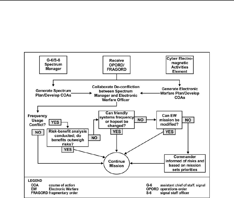
Spectrum Management Task List
31 December 2015 ATP 6-02.70 A-9
SMO TO EW FLOW CHARTS
A-19. The following flow charts describe the collaboration process between the G-6 or S-6 spectrum manager
and the EW Cell. Figure A-1 shows an overview of the entire process. Descriptions of tasks shown in these
figures that relate to spectrum manager are located beneath the chart. For more information concerning EW
Cell tasks, review ATP 3-36 and JP 3-13.1.
Figure A-1. The SMO to EW collaboration process
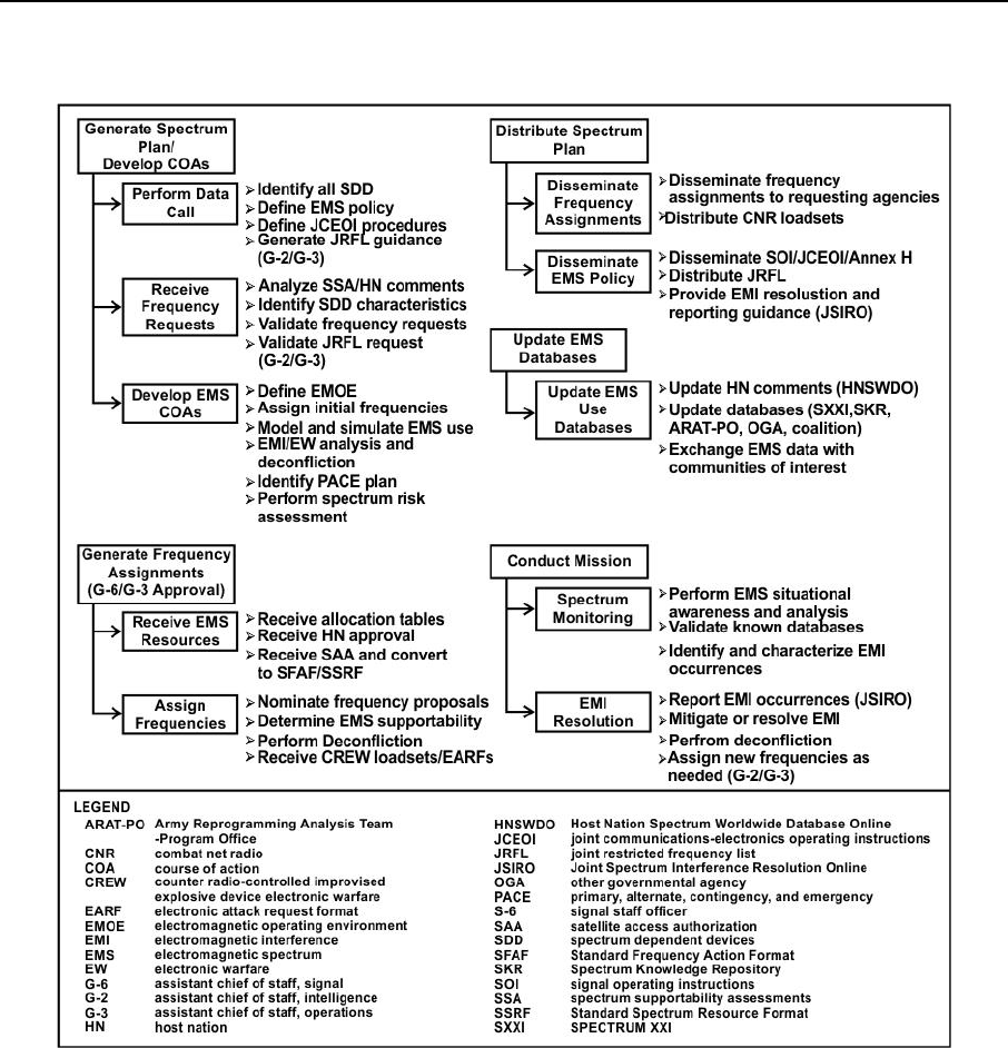
Appendix A
A-10 ATP 6-02.70 31 December 2015
A-20. Figure A-2 shows a detailed description of the SMO tasks that support the collaboration process.
Figure A-2. The G-6 or S-6 spectrum manager’s tasks
A-21. Generate Tactical Spectrum Plan and Develop COAs: The spectrum managers use various
SMO tools to plan a mission (CJSMPT, Spectrum XXI, and SPEED). The spectrum manager generates a
data call message to all subordinate units. The data call message directs the units to—
Identify all SDD.
Define spectrum policy.
Defines the procedures included on the JCEOI, and defines JRFL Guidance.
A-22. Receive Frequency Request: As the units answer the message, the spectrum manager receives
frequency requests in accordance with mandatory formats (SFAF, SSRF, NTIA or International
Telecommunications Union required items). Spectrum managers review the spectrum dependent device
characteristics and determine if each has passed the spectrum certification process (DD Form 1494), and is
supportable in the operational area by reviewing host nation comments (HNSWDO). The spectrum manager
validates frequency requests by checking for inflated requests (such as the unit requests more frequency than
needed). The spectrum manager validates JRFL requests with the G-2 and G-3; this ensures warranted

Spectrum Management Task List
31 December 2015 ATP 6-02.70 A-11
protection requests. The spectrum manager also prioritizes spectrum users, with the G-3, to aid in planning
and prioritizing frequency requests.
A-23. Develop COA: Spectrum managers develop COAs for the mission and issue initial frequency
assignments to perform modeling and simulation for the spectrum. Various SMO tools identify EMI caused
by various sources and provide deconfliction recommendations. Spectrum managers also perform a spectrum
risk assessment to determine the effects of the SDD in the area of responsibility. The commander may choose
the COA according to all of the identified spectrum issues and risks.
A-24. Generate frequency assignments: The spectrum manager receives spectrum resources, in the
form of allocation tables and permissions, from higher echelon (such as Army Spectrum Management Office,
JFMO, and host nation coordination). The spectrum manager uses SMO tools to transfer the information into
SFAF or SSRF format and place it into spectrum use databases.
A-25. Spectrum managers assign frequency and nominate frequency proposals to the approving authority
using SMO tools. Upon receiving approved frequency assignments, the spectrum manager determines
spectrum supportability of any new or revised frequencies. Spectrum managers receive counter radio-
controlled improvised explosive device EW loadsets and electronic attack request format frequencies from
the EW Cell. The spectrum manager performs deconfliction to mitigate EMI caused by EW efforts.
A-26. Distribute Tactical Spectrum Plan: The spectrum manager disseminates the plan to all required
agencies (JFMO, JSME, and CEMA element) and provides spectrum data to communities of interest such as
unified action partners. The spectrum manager generates and distributes combat network radio loadsets. The
spectrum manager disseminates approved policies for spectrum use, to include the SOI or JCEOI Annex H
(OPORD), the completed JRFL, and EMI resolution guidance (CJCSM 3320.02D).
A-27. Update Spectrum Databases: The spectrum manager updates various spectrum related databases
HNSWDO, Spectrum XXI.
A-28. Conduct Mission: Spectrum managers conduct spectrum monitoring prior to conducting the mission
to validate spectrum databases and identify differences between planned authorized frequencies and spurious
or unauthorized frequencies in use. Spectrum managers use spectrum analyzers and spectrum analysis
software to monitor frequencies. Spurious and unauthorized frequencies may be found through direction
finding and triangulation. Spectrum monitoring during the mission identifies and characterizes EMI
occurrences. Upon EMI occurrence, the spectrum manager performs EMI resolution mitigation and reporting
procedures. The spectrum manager uses the characterized data to submit a JSIR report. The spectrum
manager then follows the steps in the CJCSM 3320.02D, to attempt to resolve and mitigate the EMI at the
lowest echelon possible. If resolution is not possible, the spectrum manager provides spectrum users with
new frequency assignments.
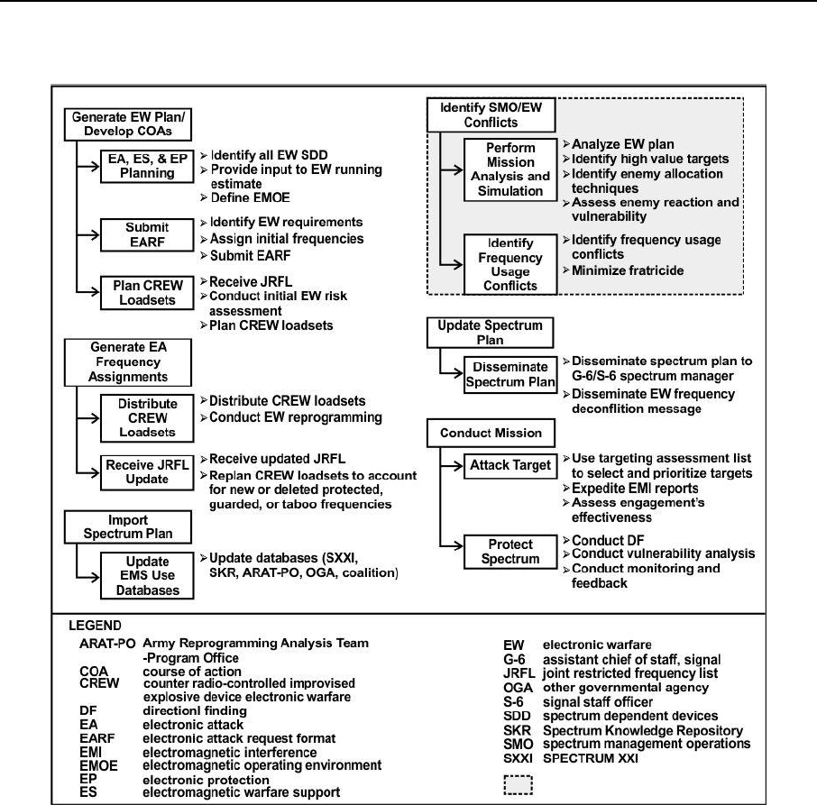
Appendix A
A-12 ATP 6-02.70 31 December 2015
A-29. Figure A-3 provides a graphic depiction of EW Cell tasks that support the SMO collaboration process.
Figure A-3. The CEMA element tasks
A-30. The CEMA element, with guidance from the S-6, G-6, G-2, and G-3, generates the EW Plan that
includes EA, electronic warfare support, and EP planning. This plan results in development of the electronic
attack request format and includes spectrum use requirements. The CEMA element plans counter radio-
controlled improvised explosive device EW loadsets.
A-31. The CEMA element plans and distributes counter radio-controlled improvised explosive device EW
loadsets to required users. The JRFL, once imported, aids in planning counter radio-controlled improvised
explosive device EW loadsets.
A-32. The CEMA element receives the tactical spectrum plan from the G-6 and S-6 spectrum manager. The
CEMA element also uses the tactical spectrum plan and SMO tools to identify conflicts caused by the EW
plan.
A-33. The CEMA element, upon determining that the EW plan causes no conflicts, updates the tactical
spectrum plan and disseminates it to the G-6 and S-6 spectrum manager. This allows the G-6 and S-6
spectrum manager to update spectrum databases and prevent frequency assignments that conflict with the
EW Plan. Battalion and brigade staff elements receive the EW plan and approve the validated plan. Upon
approval, put the EW plan into action.
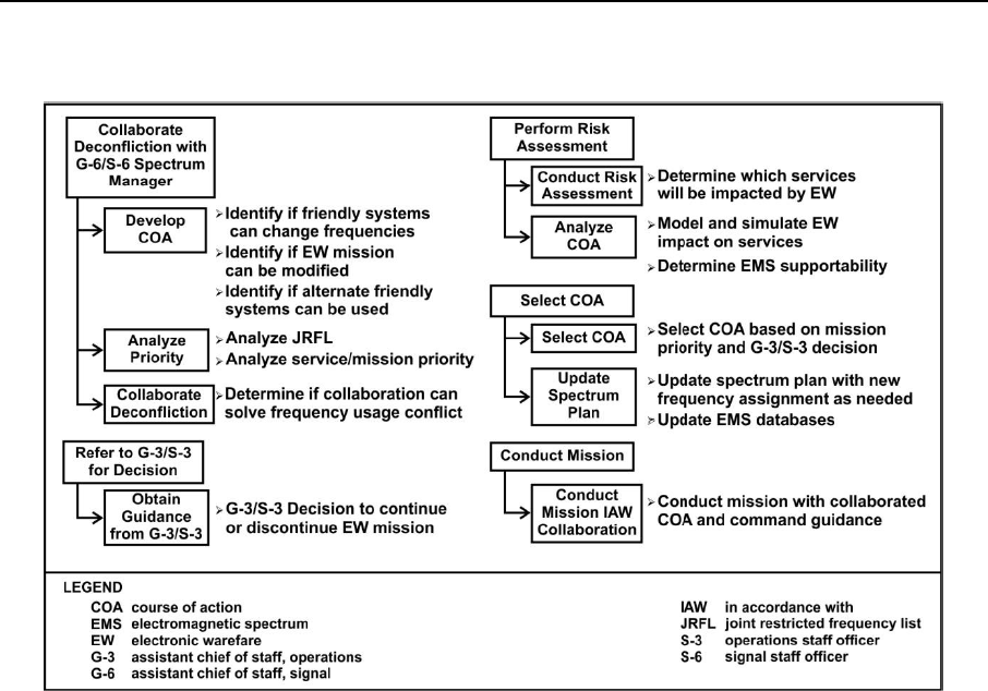
Spectrum Management Task List
31 December 2015 ATP 6-02.70 A-13
A-34. Figure A-4 shows the collaboration between the spectrum manager, the G-6, and the G-3.
Figure A-4. SMO collaboration tasks
A-35. Collaboration and deconfliction with spectrum manager occurs when the CEMA element identifies
frequency conflicts. The collaboration determines if friendly systems can change frequencies, if not, consider
possible modification of EW mission, determine if friendly forces can use a different system. If these steps
resolve the conflict, continue to conduct the mission. The G-3 determines which services or missions to end
or alter. Services or mission termination are done by priority of the EW mission or the service. Based on G-
3 guidance, the spectrum manager performs an assessment on the new, altered mission. Determine the
spectrum supportability for the mission. Develop COAs for the mission change. With direction from the G-
3, select and enact the appropriate COA. Refer to G-6 or S-6 spectrum manager and CEMA element to
conduct mission blocks.
A-36. Upon mission completion, each agency conducts after mission actions. These include submitting
frequency assignments for deletion, updating spectrum databases, and updating host nation comments to aid
in future mission planning.
This page intentionally left blank.

31 December 2015 ATP 6-02.70 B-1
Appendix B
Capabilities and Compatibility between Tools
This appendix provides an overview of the capabilities and compatibilities of various
SMO tools. There are many tools spectrum managers use to perform their duties. Due
to the many tools available, compatibility understanding is of great importance.
CAPABILITIES AND COMPATIBILITY
B-1. The spectrum manager should have an understanding of SMO tool capabilities and compatibility in
order to complete required tasks. Table B-1 shows the current compatibilities among tools with a description
of known compatibility fixes. Table B-2 on page B-2 shows the capabilities by tool with a description of each
capability.
Table B-1. Compatibility between SMO tools
TOOL
Spectrum
XXI
Spectrum
XXIO
CJSMPT
S2AS
AESOP
SPEED
ACES/JACS
HNSWDO
Spectrum
XXI
*
X
X
X
X
X
Spectrum
XXIO
*
X
X
X
X
X
X
CJSMPT
X
X
X
X
X
X
S2AS
X
X
X
AESOP
X
X
X
SPEED
X
X
X
X
ACES/
JACS
X
X
X
X
HNSWDO
X
X
X
X
X
Legend: X = formatting compatible * = limited format compatibility blank = not currently compatible
ACES automated communications engineering software
AESOP Afloat Electromagnetic Spectrum Operations Program
CJSMPT Coalition Joint Spectrum Management Planning Tool
HNSWDO Host Nation Spectrum Worldwide Database Online
JACS joint automated communications-electronics operation instructions system
S2AS Spectrum Situational Awareness System
SPEED systems planning, engineering, and evaluation device
COMPATIBILITY BETWEEN SMO TOOLS
B-2. For the purpose of this ATP, SMO tools have format compatibility if they can import and export
spectrum related files from other SMO tools without the need to modify the format. Format compatibility
between tools complies with the NCE concept and reduces time constraints for spectrum manager in a joint
environment. Limited format compatibility means that the tool has the capability of importing or exporting
spectrum related files between another tool but requires the spectrum manager to manipulate format
inconsistencies. For instance, legacy Spectrum XXI records modify or delete records in Spectrum XXI
Online, but cannot create new records.
B-3. Table B-2, on page B-2, compares SMO tool and shows the capability of each tool. A description of
each capability follows the table.

Appendix B
B-2 ATP 6-02.70 31 December 2015
Table B-2. SMO tool capabilities
SMO Capability
SMO Tools
Spectrum
XXI
Spectrum
XXIO
CJSMPT
HNSWDO
S2AS
AESOP
SPEED
ACES/
JACS
Spectrum measurement
and direction finding
X
Live Spectrum Analysis
X
EW/EMI analysis and
frequency deconfliction
(fixed location)
*
X
X
X
X
EW/EMI analysis and
frequency deconfliction
(on-the -move)
X
X
X
X
2D/3D Simulation and
Modeling of EMOE
*
X
X
X
*
X
Plan spectrum reuse and
minimize requirements
*
*
X
Import satellite access
authorization and
convert to SFAF/SSRF
X
X
“Drag and Drop” Force
structure templates
*
X
X
X
Assign Frequencies
X
X
*
*
*
*
Access JETS database
X
X
Access 2D/3D Digital
Terrain databases
*
X
X
X
X
X
Access CREW loadsets
X
X
Access HN comments
X
XML Format
X
X
X
X
X
HTML Format
X
X
CSV Format
X
X
X
Generate SOI/JCEOI
X
X
Provide input to
SOI/JCEOI
X
Generate JSIR report
X
X
X
Provide JRFL input to
higher echelon
X
X
X
X
X
SFAF Format
X
*
X
X
X
X
X
SSRF Format
X
*
X
X
Provide input to COP
X
COA Development
X
X
*
NCE Compliant
X
X
X
*
*
Standalone operations
X
X
X
X
X
X
X
Legend: X = formatting compatible * = limited format compatibility blank = not currently compatible
SMO - spectrum management
operations
ACES - automated communications
engineering software
AESOP - Afloat Electromagnetic
Spectrum Operations Program
CJSMPT - Coalition Joint Spectrum
Management Planning Tool
COA - course of action
COP - common operational picture
CSV - comma separated values
EMI - electromagnetic interference
EMOE - electromagnetic operational
environment
EW - electronic warfare
HN - host nation
HNSWDO - Host Nation Spectrum
Worldwide Database Online
HTML - hypertext markup language
JACS - joint automated communications-
electronics operation instructions system
JCEOI - joint communications-electronics
operating instructions
JRFL- joint restricted frequency list
JSIR - joint spectrum interference resolution
NCE - network-centric environment
S2AS - Spectrum Situational
Awareness System
SFAF - standard frequency action
format
SOI - signal operating instructions
SPEED - systems planning,
engineering, and evaluation
device
SSRF - standard spectrum
resource format
XML - extensible markup
language

Capabilities and Compatibility between Tools
31 December 2015 ATP 6-02.70 B-3
SMO TOOL CAPABILITIES
B-4. SMO tool capabilities are the attributes of a system or tool utilized to perform spectrum management
operations. The following list is not all inclusive and many of the SMO tools are constantly updated.
Spectrum measurement and direction finding: This tool takes measurements (live) of the
spectrum and provides direction finding of unknown, unplanned, EW, or EMI signals.
Live spectrum analysis-This tool receives spectrum measurements and provides analysis of the
measured signals over time for the purpose of frequency records, trend analysis, and EW
interference detection.
EW and EMI analysis and frequency deconfliction (fixed location): This tool analyses EW
and EMI effects (actual or planned) on spectrum use and provides recommendations and COAs
for deconfliction of the EW and EMI for stationary SDD. This also includes the analysis of second
or third order harmonics, intermodulation and electromagnetic environmental effects in the areas
impacted by spectrum use.
EW and EMI analysis and frequency deconfliction (on-the-move): Same as above, with the
exception that the tool analyzes and deconflicts SDDs while conducting communications on-the-
move.
Two or three-dimensional simulation and modeling of EMOE: This tool provides both a two
and three-dimensional model of the EMOE to include topography, electromagnetic environmental
effects, and color-coded spectrum footprints.
Plan spectrum reuse and minimize requirements: This tool minimizes the impact of a mission
on the spectrum through the reuse of frequencies in different locations and planning for the
minimum requirements for spectrum users and provides for more flexible and available spectrum
resources for all users.
Import Satellite Access Authorization and convert to SFAF or SSRF: This tool imports an
authorization and automatically converts it to the SFAF or SSRF approved format. This capability
provides a more complete spectrum database and aids in the mitigation of EMI caused by or
affecting space based SDD.
Force structure templates: This tool has the capability of creating or accessing force structures
and placing them quickly and easily on the three-dimensional map of the battlefield using drag
and drop, with associated SDD and the general spectrum requirements for those devices.
Assign frequencies: The tool can assign frequencies to users that have submitted a frequency
proposal in the correct format (SFAF or SSRF). A check mark means that the tool is capable and
authorized to assign frequencies. An asterisk means that the tool may assign and plan for projected
frequencies approved by another tool prior to use of the projected frequency.
Access joint spectrum center equipment, tactical, and space (JETS) database: This tool may
query the JETS database for information and receive updates (refreshes) from the database.
Access three-dimensional Digital Terrain databases: This tool imports detailed three-
dimensional digital terrain data from a variety of sources, such as the terrain integrated rough earth
model, or Google Maps for the purpose of planning, managing, and visualizing the EMOE. If
marked with an asterisk, the tool has limited capabilities, such as two-dimensional maps only.
Access counter radio-controlled improvised explosive device EW loadsets: This tool can
access counter radio-controlled improvised explosive device EW loadsets for frequency
deconfliction planning.
Access Host Nation comments: This tool has access to host nation allocation tables that aid in
planning spectrum use in various host nation locations. If marked with an asterisk, the tool has
limited access, such as relying on importing data from another tool.
XML Format-Extensible Markup Language (XML) is a file format that is rapidly becoming
the standard for compatibility between software packages. If selected, the tool may import or
export various files (records, reports, and data) in XML format.
HTML Format: Hypertext Markup Language (HTML) is the main markup language for creating
web pages and other information displayed in a web browser. HTML elements form the building
blocks of all websites. HTML allows embedding images and objects within web pages to create

Appendix B
B-4 ATP 6-02.70 31 December 2015
interactive forms. It provides a means to create structured documents by denoting structural
semantics for text such as headings, paragraphs, lists, links, quotes and other items.
Comma-separated values (CSV) Format: CSV is a common, relatively simple file format that
is widely supported by consumer, business, and scientific applications. Among its most common
uses is moving tabular data between programs that natively operate on incompatible (often
proprietary or undocumented) formats. This works because so many programs support some
variation of CSV at least as an alternative import or export format. If checked, the tool can import
or export various files in CSV format.
Generate SOI or JCEOI: SOI or JCEOI provide for policies and regulations to subordinate units.
If selected, the tool may generate and disseminate SOI or JCEOI in the correct format to
subordinate units.
Provide input to SOI or JCEOI: This tool provides input to the SOI or JCEOI in compatible
formats, but cannot generate the SOI or JCEOI.
Generate JSIR report: Use the JSIR report format to report EMI occurrence to the next higher
echelon in a joint task force operating environment. This tool has the capability of generating the
JSIR report in the correct format and exporting the report to the next higher echelon.
Provide JRFL input to higher echelon: The JRFL is a time and geographically oriented listing
of functions, nets, and frequencies requiring protection from friendly EW. This tool allows the
operator to process JRFL input from subordinate forces, provide the input to higher echelons in
the correct format, and distribute the JRFL to concerned units upon approval from higher echelon.
SFAF Format: This tool can propose, assign, modify, renew, review, and delete radio frequencies
in the SFAF (MCEB Pub 7) approved format. If marked with an asterisk, the tool has limited
capabilities, such as it can only import and read a SFAF frequency record.
SSRF Format: This tool can propose, assign, modify, renew, review, and delete radio frequencies
in the SSRF (MCEB Pub 8) approved format. If marked with an asterisk, the tool has limited
capabilities, such as the tool requires manual workarounds to generate proposals in the SSRF
approved format.
Provide input to COP: The COP is a single identical display of relevant information shared by
more than one command. This tool can interface and provide relevant spectrum information to the
COP.
COA Development: This tool can analyze spectrum resources impacted by a mission and develop
many COAs to determine how to best support the mission and mitigate spectrum conflicts.
NCE Compliant: This tool is compliant with the NCE concept by providing central locations for
access of information (through SIPRNET or NIPRNET) to authorized users both within an agency
(vertically) and between agencies (horizontally) in joint environments. If marked with an asterisk,
the tool is only partially NCE compliant, such as not providing information between agencies.
Operate in standalone environment: This tool can operate while disconnected from outside
agencies or central databases.
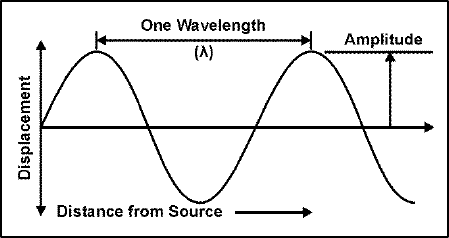
31 December 2015 ATP 6-02.70 C-1
Appendix C
Spectrum Physics
This appendix describes the physics of radio frequency (RF) spectrum. A basic
understanding of the underlying principles of RF energy is necessary to the execution
of spectrum management operations.
RADIO FREQUENCY
C-1. RF communications, based on the laws of physics, describes the behavior of electromagnetic energy
waves. RF communication works by creating electromagnetic waves at a source and being able to receive
those electromagnetic waves at a particular destination. These electromagnetic waves travel through the air
at the speed of light. The wavelength of an electromagnetic signal is inversely proportional to the frequency;
the higher the frequency, the shorter the wavelength.
C-2. Frequency measurements are in Hz (cycles per second) and radio frequency measurements are in kHz
(thousands of cycles per second), MHz (or millions of cycles per second) and GHz (or billions of cycles per
second). The wavelength for a device utilizing a frequency in the MHz range is longer than frequency in a
GHz range. In general, signals with longer wavelengths travel a greater distance and penetrate through, and
around objects better than signals with shorter wavelengths.
C-3. Waveforms are patterns of electrical energy over time. A Sine wave is the fundamental building block
of electricity and other energies. A Sine wave mathematically defines a natural action describing a harmonic
alternating event.
C-4. Figure C-1 provides a graphic depiction of a simple waveform. Displacement is the crest (high point)
and trough (low point) of a wave. The wavelength is the distance from one crest to another or trough to
another. Amplitude is the height of a crest or trough.
Figure C-1. Waveform characteristics
HARMONICS AND INTERMODULATION PRODUCTS
C-5. Frequencies are associated with different standing wave patterns that produce wave patterns known as
harmonics. Figure C-2 on page C-2, displays the relationship between the wave that produces the pattern and
the length of the medium in which the pattern is displayed. The pattern for the first harmonic reveals a half
wavelength where each point on the line represents nodes and the arching middle represents antinodes. The
second harmonic displays a complete wavelength; this pattern described as starting at the rest position, rising
upward to a peak displacement, returning down to a rest position, then descending to a peak downward
displacement and finally returning back to the rest position.
C-6. One complete wave in a standing wave pattern consists of two loops. Thus, one loop is equivalent to
one-half of a wavelength. The third harmonic pattern consists of three anti-nodes. Thus, there are three loops
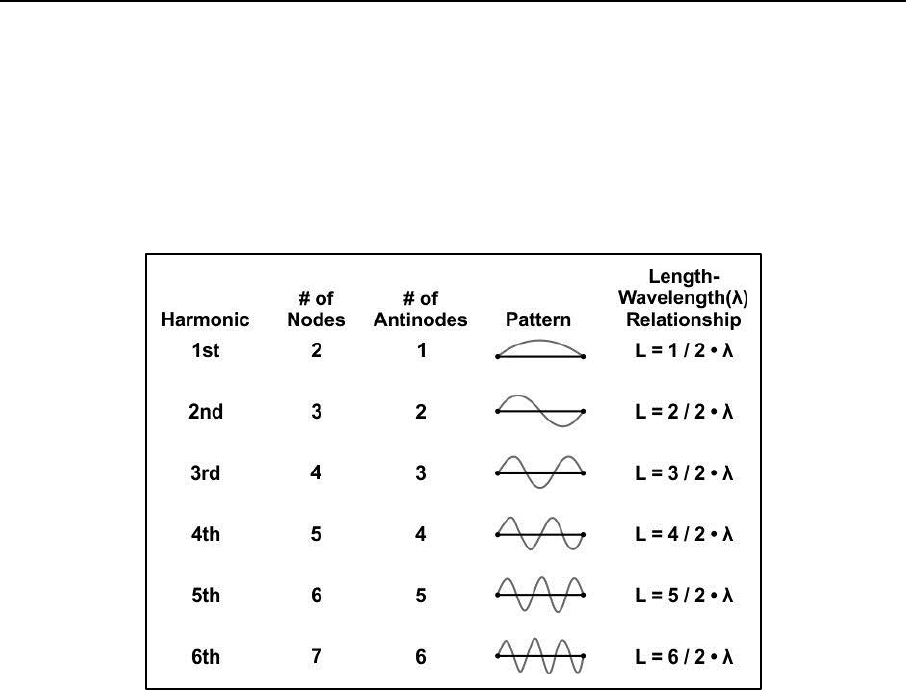
Appendix C
C-2 ATP 6-02.70 31 December 2015
within the length of the wave. Since each loop is equivalent to one-half a wavelength, the length of the wave
is equal to three-halves of a wavelength. The table has a pattern when inspecting standing wave patterns and
the length-wavelength relationships for the first three harmonics. The number of antinodes in the pattern is
equal to the harmonic number of that pattern. The first harmonic has one antinode; the second harmonic
has two antinodes; and the third harmonic has three antinodes. The mathematical relationship simply emerges
from the pattern and the understanding that each loop in the pattern is equivalent to one-half of a wavelength.
The general equation that describes this length-wavelength relationship for any harmonic is on the right side
column of Figure C-2.
Figure C-2. Wavelength relationship
C-7. Harmonics develop into currents and voltages with frequencies that are multiples of the fundamental
frequency. Harmonic signals that fall within the pass band of a nearby receiver and the signal level are of
sufficient amplitude can degrade the performance of the receiver. Receivers live under constant bombardment
of signals which enter through the antenna port. Some of these signals quickly attenuate due to front-end
filtering, which is often referred to as pre-selection.
C-8. Intermodulation generation occurs when multiple signals reach a non-linear element such as a detector,
mixer, or amplifier and are mixed. Whenever signals are mixed, two additional signals are introduced as the
sum and difference of the original frequencies. This process is often intentional as in the case of mixing a
frequency with the intermediate frequency in a system to produce the desired operating signal. Harmonics of
the original two frequencies are still present but most occur well outside the pass band of the RF and
intermediate frequency filters and cause no problems. The harmonics that tend to cause the most problems
are the odd-order products. For example, if a 50 MHz mixing frequency is combined with a 98 MHz
intermediate frequency to produce a desired transmission signal of 148 MHz, this is very close to the 3
rd
order
harmonic of 50 MHz (150 MHz) and may cause interference at the desired frequency. Channelized
communications systems tend to suffer more from these issues due to the uniform spacing of the channels.
TRANSMISSION, PROPAGATION AND RECEPTION
C-9. A radio transmits a signal by driving a current on an antenna where the current amplitude is the
changing quantity of the signal. This changing current, in turn, induces an electromagnetic field about itself,
with a field strength that corresponds to the current amplitude. This electromagnetic field propagates away
from the antenna as a wave at the speed of light. As the signal propagates, it attenuates. At a distant receiver,
the electromagnetic wave passes across the receiver’s antenna and induces a current. Figure C-3 shows
transmit waves and propagation.
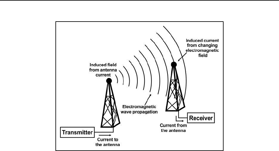
Spectrum Physics
31 December 2015 ATP 6-02.70 C-3
Figure C-3. Transmission and propagation of electromagnetic waves
C-10. Electromagnetic radiation in the area passes across the receiving antenna. To detect and receive the
correct signal, the receiving antenna must be able to isolate the desired signal from all others. If the receiver
is in range of two transmitters using the same frequency band it is attempting to receive, then the receiver
may not properly capture the desired signal for demodulation. The receive signal captured may be
unintelligible. The spectrum management process attempts to prevent this situation from occurring. The goal
is not to prevent transmitters from using the same frequencies but to ensure that receivers are capable of
receiving and distinguishing the desired signals. There may be more than one transmitter using the same
carrier frequency as long as the receivers are able to distinguish the desired signal over the others.
This page intentionally left blank.
31 December 2015 ATP 6-02.70 D-1
Appendix D
Spectrum Management Lifecycle
The Army spectrum management lifecycle serves as a guide to follow in establishing
a functional and efficient spectrum management program. The lifecycle encompasses
the complete process of providing spectrum management support to the commander
and is applicable to all spectrum managers regardless of duty location. The Army
spectrum management lifecycle mirrors the joint task force lifecycle.
SPECTRUM MANAGEMENT LIFECYCLE
D-1. The spectrum management lifecycle consist of 12 activities that enhance SMO. It is not imperative to
conduct the lifecycle activities in order as presented. Many spectrum managers conduct activities in the
lifecycle simultaneously. Listed below are steps of the spectrum management lifecycle—
1. Define command specific policy and guidance.
2. Gather requirements.
3. Develop electromagnetic spectrum requirements summary.
4. Define the EMOE.
5. Obtain spectrum resource.
6. Develop spectrum management plan.
7. Nominate and assign frequencies.
8. Generate the joint communication-electronic operating instructions.
9. Develop the JRFL.
10. Perform electronic warfare deconfliction.
11. Resolve interference.
12. Report interference.
STEP 1. DEFINE COMMAND SPECIFIC POLICY AND GUIDANCE
D-2. Unit standard operating procedures establish specific guidance for managing, requesting, coordinating,
and assigning spectrum use, the JRFL process, communications electronic operating instructions, and other
processes. Policy and guidance information should be available in the commander’s spectrum guidance,
spectrum management manual, command regulations, instructions, or existing plans.
D-3. Spectrum managers require many resources. The unit standard operating procedures would establish
the basic spectrum management resources needed to establish a spectrum management element in support of
operations anywhere within the commander’s operational area. Such resources should include digitized
terrain data, background electromagnetic environment records, country area studies, copies of agreements
for spectrum use or sharing with involved or adjacent host nations, and historical spectrum use records
involving the operational area. This step generates two deliverable products: the spectrum concept and the
spectrum requirements data call message.
D-4. The spectrum management concept is the vision of spectrum management operations best practices
performed to support the mission. The spectrum management concept comprises assumptions,
considerations, and restrictions that, when analyzed together, can illustrate the best approach to managing
the EMOE.
D-5. The spectrum requirements data call message provides guidance to staff elements, components, and
supporting agencies on how to request spectrum support for spectrum dependent systems that operate under
their control within area of influence. This multipart message should cover the following subjects: spectrum
management policy and guidance, security classification guidance, frequency and communications electronic
operating instructions master net list request procedures, as well as provide guidance for identifying nets and
frequencies to be included on the JRFL.

Appendix D
D-2 ATP 6-02.70 31 December 2015
STEP 2. GATHER REQUIREMENTS
D-6. Gathering requirements can begin as soon as spectrum management receives guidance and
coordination channels are defined. Spectrum managers must also obtain the requirements of spectrum users,
primarily the staff elements. These requirements must address both communications and non-
communications such as radar and weapons systems and stated in terms of spectrum requirements to support
the command. This step involves undocumented requirements from sources external to the spectrum
management coordination chain.
STEP 3. DEVELOP THE SPECTRUM REQUIREMENTS SUMMARY
D-7. This summary quantifies the amount of spectrum necessary to support the command, determine the
necessity of using frequency sharing and reuse plans, and help in the development of allotment or channeling
plans. This process requires compiling and analyzing the data previously generated. The spectrum manager
analyzes the summary and determines the amount of spectrum required. In addition, the spectrum
requirements summary determines the number of different radio services competing for spectrum in the same
frequency band, determines the different emissions utilizing a particular band, and supports development of
a plan for frequency sharing.
D-8. The spectrum requirements summary generated is a compilation of the requirements identified in
response to the spectrum requirements data call message. This product is for the sole use of the spectrum
manager and provides a tool to base future decisions about efficient spectrum-use and initial requirements
definition. This product may assist the spectrum manager in requesting spectrum from a host nation, or to
better allocate portions of the spectrum, to support emitters utilizing varying bandwidths.
STEP 4. DEFINE THE EMOE
D-9. Military operations require a common, single, authoritative source for spectrum use information for all
friendly, enemy (to the extent available), neutral, and civil emitters and receivers to achieve and manage
successful joint spectrum use. This common source of spectrum use information found within the EMOE
must be current, accurate, and accessible to authorized users. The spectrum manager is responsible for
building and managing this common source of information.
D-10. The EMOE database contains spectrum use information on all friendly military and civilian, available
enemy, and neutral forces. Defining the EMOE not only creates a database of frequency assignments, but
also identifies factors that affect signal propagation such as environmental characteristics and terrain. This
activity starts with defining your operational area and its environmental characteristics, locating necessary
terrain data and then locating the data for and creating a database of the known spectrum use information.
Defining the EMOE is an ongoing activity. The information produced by this activity provides a baseline
database digitally depicting the EMOE and the basis for all spectrum interaction analyses.
STEP 5. OBTAIN SPECTRUM RESOURCES
D-11. Obtain spectrum resources needed to support the command. The spectrum manager coordinates
military spectrum use with the spectrum management authority of the host nation or coalition forces involved.
The host nation can request spectrum resources for exercises or most military operations other than war.
Operations that preclude prior coordination with a host nation, such as forced entry, require the spectrum
manager to determine the spectrum resource; evaluation of the background and history of the electromagnetic
environment provides support to the spectrum manager. If required, an evaluation of the background
environment is essential to establish well-defined spectrum requirements and for the EMOE to remain as up-
to date as possible.
D-12. The spectrum requirements summary can help quantify the amount of spectrum needed and identify
the different radio services and emissions that may be operating within each frequency band.
STEP 6. DEVELOP THE SPECTRUM MANAGEMENT PLAN
D-13. Unit standard operating procedures establish specific guidance for managing, requesting, coordinating,
and assigning spectrum use and procedures for JRFL and JCEOI processing. Additionally, the spectrum

Spectrum Management Lifecycle
31 December 2015 ATP 6-02.70 D-3
manager is the focal point for inclusion of spectrum use considerations in the Annex H development and
provides administrative and technical support for military spectrum use. This process uses the spectrum
management concept, developed in the first activity, along with existing policy and guidance. Other sources
of information are lessons learned from previous operations and exercises, the JSC and other spectrum
managers.
D-14. The spectrum manager devises a plan to use spectrum resources available. This plan depends upon the
products of all the previous activities. Spectrum managers evaluate spectrum management plans for possible
improvement on a regular basis. The spectrum management plan is typically included as an appendix to
Annex H of an OPLAN or OPORD and evolves from guidance as the operation or exercise transitions from
the planning to execution phase.
D-15. The spectrum management plan provides guidance for all spectrum management functions, including
information exchange, expected coordination channels, format for deliverable products, interference and
reporting resolution procedures, and suggested resolution steps.
STEP 7. NOMINATE AND ASSIGN FREQUENCIES
D-16. Nominate and assign frequencies is the actual implementation of the spectrum management plan.
Authority, delegated to components, to issue frequency assignments or allotments provides the maximum
latitude and flexibility in support of combat operations. This activity involves the initial assigning of
frequencies. The spectrum manager may assign frequencies or delegate (decentralize) assignment authority
using frequency pools (allotment plans) provided to functional and service component spectrum managers
allowing them to assign frequencies.
D-17. The frequency assignment database, which conforms to and is created based on the table of frequency
allocations, radio regulations, and channel plans, is the most important resource the spectrum manager has
available and forms the basis for nominating interference free assignments, providing impact analyses of EW
operations, and identifying and resolving interference issues.
STEP 8. GENERATE A COMMUNICATIONS-ELECTRONIC OPERATING INSTRUCTIONS
D-18. The CEOI is a two-part document. Part 1 is a directory of radio nets or units and their associated
frequencies, call signs, call words, and network identification listed by time period. Part 2 contains
supplemental procedures for electronic, visual, and verbal interactions, such as sign or countersigns,
obscurants or pyrotechnics and suffix or expanders. CEOI development and distribution is an S-6 or G-6
responsibility and delegated to the spectrum manager.
D-19. The JCEOI provides communications details and information for joint forces, service-specific
elements and units including—
Daily changing and non-changing frequency assignments.
SINCGARS cue, manual and net identification assignments.
Call sign assignments.
Call words assignments.
Daily changing code words.
Running passwords.
D-20. Information found in the JCEOI includes document-handling instructions, controlling authority data,
effective dates and reproduction instructions. Due to the sensitive information contained in the JCEOI,
classification should be at the same level. When jointly used, the Army CEOI becomes the Joint CEOI or
JCEOI.
Note. The JCEOI is the most widely used communication control document in any given
operational area.

Appendix D
D-4 ATP 6-02.70 31 December 2015
D-21. Overarching regulatory guidance for JCEOI management, to include call signs and call words, is
contained within the CJCSM 3320.02, JCEOI publication. Additional guidance may apply based on
command relationships with other unified action partners.
D-22. During operations, the combatant commander is the authority for the JCEOI. The combatant
commander may delegate this authority, to the ground component commander or the respective joint task
force commander. There is a distinction between the air and ground component JCEOI. The relevant air
component issues a Special Instructions document that is the air operations equivalent of the JCEOI.
D-23. Within garrison, the Army Command, Army Service component command, or direct reporting unit
commander has responsibility for CEOI production and distribution in support of training requirements. U.S.
Forces Command may delegate authority to a corps, division or remain centralized to meet installation-
training objectives. Regardless of echelon, the commander is responsible for the JCEOI. The J-6 or G-6
develops and promulgates the JCEOI. The J-3 or G-3 validates master net list requirements and resolves
conflicts.
Distribution and Development
D-24. The COMSEC facility provides distribution of the final ACES or JACS produced JCEOI product.
Doing so ensures all units receive the latest JCEOI with the distribution of COMSEC. Communications cards
are derivative products of the JCEOI and are METT-TC driven. Document and protect communications cards
in the manner appropriate for their security classification level. These products inherit the classification level
of the source JCEOI material.
D-25. When operationally required to maintain administrative tempo with the pace of operations it may be
necessary to go without management of the SINCGARS compatible loadset via ACES or JACS and maintain
the list of SINCGARS networks using a spreadsheet. ACES or JACS generates the loadset.
Call Words, Call Signs, Suffixes and Expanders
D-26. Call signs and call words establish and maintain communications. They identify the radio stations of
command authorities, activities, facilities, units, elements, or individual positions. Call signs do not identify
people. Tactical call sign systems meet specific military requirements under an exemption to the International
Telecommunications Union radio regulations.
Call signs are a combination of alphanumeric or phonetically pronounceable characters that
identifies a communication facility, command, authority, activity, or unit; used primarily for
establishing and maintaining communications.
Call words identify units when communicating within a secured communications net. The
generation of call words differ based on service component command guidance or directed based
off command authority.
Suffixes and expanders further assist in identifying a radio station’s position or function. Care in
the management of call words ensures that each station sounds phonetically different over voice
transport (for example MAD DAWG 6 or MAD DOG 6). Call word usage is for secure networks
only.

Spectrum Management Lifecycle
31 December 2015 ATP 6-02.70 D-5
D-27. Table D-1 provides an explanation of call sign, call word, suffix and expander.
Table D-1. Call signs, call words, suffix and expander
Item
Name
Example
Explanation
Call Sign
X6Y24E
B9K60H
The term “call sign” refers to the letter-number-letter combination that typically
designates a unit element in the CEOI or JCEOI. CJCSI 3320.03A specifies that
the call sign should remain daily, changing in the event that the ability to
communicate securely is lost.
Examples:
X6Y= 1/A/1-25 INF (1
st
Platoon, A Co., 1-25 INF Bn)
Call Word
Bulldog24E
Fury60H
Pronounceable words that identify a communications facility, command,
authority, activity or unit; serves the same functionality as the call sign. The
Army does not have set call words per unit.
Call word deconfliction is typically handled by the highest level spectrum
manager.
EXAMPLES:
Bulldog = 1/a/1-25 INF (1
st
Platoon, A Co., 1-125 INF Bn)
Suffix
X6Y24E
B9K60H
Bulldog24E
Fury60H
The term “suffix” refers to the two digits assigned to a particular position,
mission or function within a unit or element.
EXAMPLES:
24 = AVN Officer/NCO
60 = G-6 or S-6
Expander
X6Y24E
B9K60H
Bulldog24E
Fury60H
A single letter code (A through Z) used in conjunction with a suffix and call sign
to identify a sub-element of the position, mission, or function.
EXAMPLES:
E = NCOIC
H = Officer in charge
Legend
ACES automated communications engineering software
AVN aviation
Bn battalion
CEOI communications-electronics operating instruction
CJCSI Chairman of the Joint Chiefs of Staff Instruction
Co company
INF infantry
JACS joint automated communications-electronics operation instructions system
JANAP joint Army, Navy, Air Force publication
JCEOI joint communications-electronics operating instructions
NCO noncommissioned officer
NCOIC noncommissioned officer in charge
SOI signal operating instructions
Security Classification
D-28. The content of the JCEOI, master net list, and communications card extracts determine the
classification levels. The level of COMSEC key tag information entered into the system for ACES terminal
and corresponding generated loadsets determine the classification. Similar to a classified presentation, the
overall classification of a specific product would be the highest level of classification it contains.
Note. See AR 380-5 for security classification markings.
STEP 9. DEVELOP JOINT RESTRICTED FREQUENCY LIST
D-29. The JRFL is a time and geographically oriented listing of functions, nets, and frequencies requiring
protection from friendly spectrum users. Developing the JRFL requires the spectrum manager to prepare and
combine G-2, G-3, G-6, and component inputs to develop a JRFL for approval by the G-3, and when required,
periodically update and distribute the JRFL.
D-30. The JRFL is a G-3 product; it protects communications nets, from enemy communications nets
exploitation, and safety of life frequencies used by the command and local civil noncombatants. The
development, distribution, and maintenance of the JRFL is a task of the S-6 or G-6 and normally

Appendix D
D-6 ATP 6-02.70 31 December 2015
accomplished by the spectrum manager. Creation of the JRFL is for the CEMA element and based on
guidance established by the commander, EWO and the CEMA working group.
D-31. Leaders should become familiar with the types of protection status codes that exist for the JRFL.
Knowing these status codes allows the EWO to plan jamming operations on the unrestricted frequencies for
training and during operations. Three types of protection status codes apply to frequency assets identified for
inclusion in a JRFL. Sample JRFL restriction status codes include—
Taboo frequencies: Taboo frequencies are any friendly frequencies of such importance that they
must never be deliberately jammed, interfered with by friendly forces. Normally, these include
international distress, safety, stop buzzer, and controller frequencies. These frequencies include
international distress, safety, and controller frequencies. They are generally long-standing as well
as time-oriented. (JP 3-13.1)
Protected frequencies: Those friendly frequencies used for a particular operation, identified and
protected to prevent them from inadvertent jamming by friendly forces while engaged in active
EW operations against hostile forces. These frequencies are of such critical importance that
jamming should be restricted unless necessary or until coordination with the using unit is made.
These frequencies are generally time-oriented, may change with the tactical situation, and updated
periodically. Protected frequencies are friendly frequencies used for a particular operation. An
example of a protected frequency would be the command net of a maneuver force engaged in the
fight. (JP 3-13.1)
Guarded frequencies: Guarded frequencies are those enemy frequencies that maybe currently
exploited for combat information and intelligence. Guarded frequencies are time-oriented in that
the list changes as the enemy assumes different combat postures. These frequencies may be
jammed after the commander has weighed the potential operational gains against the loss of the
technical information gained. (JP 3-13.1)
STEP 10. PERFORM ELECTRONIC WARFARE DECONFLICTION
D-32. The S-3 or G-3 EW spectrum manager participates in the CEMA element representing spectrum
management issues. This includes providing EW deconfliction analysis. The EWO identifies planned EA
missions and request the spectrum manager perform an analysis on the impact of these missions to operations.
This process requires information from the JRFL, communications electronic operating instructions, and
EMOE. The analysis determines what impact the EA mission has on communication nets, systems, enemy
communications nets exploitation, and possible safety of life situations.
D-33. This product provides the CEMA element with an analysis of the potential impact of friendly EW
operations on friendly forces. The CEMA element then decides if the benefits of the jamming mission
outweigh the dangers of the potential fratricide. This product is time sensitive and produced on an as needed
basis.
STEP 11. RESOLVE INTERFERENCE
D-34. Resolving interference is a daily activity once forces have deployed and is part of the planning process.
This activity encompasses the reporting and attempting to resolve EMI. Interference maybe created by
various factors such as unauthorized users, faulty nomination criteria, lack of timely data exchanges, or
equipment problems. Victims of interference should ensure every effort to resolve frequency interference
locally. Multiple interference problems may indicate adversary EW operations, unintentional impact of blue
or grey EW operations or errors in the spectrum management plan. The spectrum manager should define and
analyze the EMOE to help determine the cause of an EMI problem.
STEP 12. REPORT INTERFERENCE
D-35. Spectrum congestion and the nature of military operations make some level of EMI likely. Interference
reporting and tracking provides the spectrum manager with a valuable historical reference for resolving future
EMI problems. After performing interference analysis, always create an interference report to document the
results.

Spectrum Management Lifecycle
31 December 2015 ATP 6-02.70 D-7
D-36. Keep these reports in a database used as a history of interference problems. The purpose of the
interference report database is to provide the spectrum manager with a repository for previous interference
incidents and steps taken to resolve them. This database provides a wealth of information on unit discipline,
training deficiencies, and a starting place for the spectrum manager to begin resolving interference issues.
Spectrum managers share this database with all. To the extent, unexplained interference persists or recurs
coincident with either red, blue or grey operations, notification to the CEMA element occurs.
D-37. Spectrum managers must be involved at the onset of interference. Spectrum managers are responsible
for resolving and reporting of interference within their responsible area. This includes setting alerts in JSIRO
for interference affecting the units operations. They receive notifications by secure email of interference
reports submitted for action and situational understanding of the interference. Spectrum managers assist and
mitigate spectrum interference at the lowest level possible and should be knowledgeable of all forms of
jamming, deception, and interference. Users experiencing EMI may change frequencies only when the
spectrum manager coordinates authorized replacement frequencies. Guidance for the JSIR program is
contained within the CJCSM 3320.02 series manuals and instructions. Additional procedural guidance in
support of the JSIR program may apply based off command relationships such as military departments, Army
commands, and combatant commands.
Joint Spectrum Interference Report
D-38. Victims of interference report EMI using JSIRO. JSIRO is a web-based, centralized application
containing data and correspondence for reported EMI, intrusion, and jamming incidents. It is the repository
for the results of analyses, collected data, and supporting documentation for EMI resolution to support both
trend and future interference resolution analysis. JSIRO and CJCSM 3320.02 provide an operator checklist
for local investigations.
D-39. EMI is any electromagnetic disturbance that interrupts, obstructs, degrades, or limits the effective
performance of electronics and electrical equipment. EMI can be induced intentionally, as in some forms of
electronic warfare, or unintentionally, as a result of spurious emissions, responses or intermodulation
products.
D-40. EMI mitigation begins with operator-level troubleshooting and reporting. It is imperative that affected
users attempt to resolve EMI incidents at the lowest possible level. Troubleshooting may identify the source
of the interference as truly EMI or, as in most cases, an equipment or operator failure. Reporting facilitates
situational understanding and supports the development of solutions. Report and investigate all prohibitive
EMI through the JSIR program. Not all EMI incidents are prohibitive however; prohibitive EMI has an
operational impact. Trained equipment operators should identify the difference between prohibitive EMI,
equipment failure, and purposeful interference by the adversary. The JSIRO report is submitted through
intelligence channels by the appropriate authority if the interfering signal is determined to be from a hostile
source,
D-41. The spectrum manager or the victim of interference is responsible for reporting interference using the
JSIR format with the information described in table D-2.
Table D-2. Data input for JSIR offline reporting
Item
Number
Data Input
1
Frequencies affected by the interference.
2
Locations of systems experiencing the interference.
3
The affected system name, nomenclature, manufacturer (with model number), or other system
description. If available, include the equipment characteristics of the victim receiver, such as bandwidth,
antenna type, and antenna size.
4
The operating mode of the affected system. If applicable, include the following: frequency agile, pulse
Doppler, search, and upper and lower sidebands.
5
The characteristics of the interference (noise, pulsed, continuous, intermittent, frequency, or bandwidth).
6
The description of the interference effects on victim performance (reduced range, false targets, reduced
intelligibility, or data errors).

Appendix D
D-8 ATP 6-02.70 31 December 2015
Table D-2, Data input for JSIR offline reporting (continued)
Item
Number
Data Input
7
Enter the dates and times the interference occurred. Indicate whether the duration of the interference is
continuous or intermittent, the approximate repetition rate of the interference, and whether the amplitude
of the interference is varying or constant. Indicate if the interference is occurring at a regular or irregular
time of day, and if the occurrence of the interference coincides with any ongoing local activity.
8
The location of possible interference sources (coordinates or line of bearing, if known; otherwise, state as
unknown).
9
A listing of other units affected by the interference (if known) and their location or distance, and bearing
from the reporting site.
10
Clear and concise narrative summary information about the interference, and any local actions taken to
resolve the problem. The operator is encouraged to provide any other information, based on observation
or estimation that is pertinent in the technical or operational analysis of the incident.
Identify whether the information furnished is an actual observation, measurement or estimate. Avoid the
use of Army or program jargon and acronyms.
11
Reference message traffic related to the interference problem reported. Include the message date-time
group, originator, action addressees, and subject line.
12
Indicate whether identification or resolution of the problem is completed.
13
Indicate if joint spectrum interference resolution (JSIR) technical assistance is desired or anticipated.
14
Point of contact information, including name, unit, and contact phone numbers.
D-42. The spectrum manager or victim of interference, reports the types of interference signals, the actions
used to overcome the interference, the suspected cause and other comments related to the interference signal.
Send this report online or forward offline as soon as feasible, based on situation.
Types of Jamming Signals
D-43. Jamming is an effective way for the adversary to disrupt mission command. All the adversary needs to
jam is a transmitter tuned to our frequency with enough power to override friendly signals at our receivers.
There are two modes of jamming. Spot jamming is concentrated power directed toward one channel or
frequency. Barrage jamming is power spread over several frequencies or channels at the same time.
D-44. Jamming can be difficult, and sometimes impossible to detect. Users of spectrum devices have the
potential of being jammed and should be able to recognize jamming. The two types of jamming most
commonly encountered are obvious and subtle jamming. Obvious jamming is normally very simple to detect.
When experiencing a jamming incident, it is more important to recognize and overcome the incident than to
identify it formally. The spectrum manager or victim reports the type of jamming signal during the JSIR
process. The more commonly used jamming signals of this type are—
Random noise. This is synthetic radio noise. It is random in amplitude and frequency. It is similar
to normal background noise and can degrade all types of signals. Operators often mistake it for
receiver or atmospheric noise and fail to take appropriate actions.
Stepped tones. These are tones transmitted in increasing and decreasing pitch. They resemble the
sound of bagpipes. Single-channel voice circuits are normally the victims of stepped tones.
Spark. The spark signal produces the most easily and effective type of jamming. Bursts are of
short duration and high intensity. Spark jamming signals, repeated at a rapid rate, is effective in
disrupting all types of radio communications.
Gulls. The gull signal is a quick rise and slow fall of a variable radio frequency and is similar to
the cry of a sea gull. It produces a nuisance effect and is very effective against voice radio
communications.
Random pulse. In this type of interference, pulses of varying amplitude, duration, and rate are
generated and transmitted. They disrupt teletypewriter, radar, and various types of data
transmission systems.
Wobbler. The wobbler signal is a single frequency modulated by a low and slowly varying tone.
The result is a howling sound that causes a nuisance effect on voice radio communications.

Spectrum Management Lifecycle
31 December 2015 ATP 6-02.70 D-9
Recorded sounds. Recorded sounds are any audible sound, especially of a variable nature, to
distract radio operators and disrupt communications. Music, screams, applause, whistles,
machinery noise, and laughter are examples of recorded sounds jamming.
Preamble jamming. This type of jamming occurs when a broadcast resembling the
synchronization preamble speech of security equipment over the operating frequency of secure
radio sets. Preamble jamming results in all radios being locked in the receive mode. It is especially
effective when employed against radio nets using speech security devices.
Subtle jamming. Subtle jamming is not obvious; no sound from the receiver radio. The radio
cannot receive the intended incoming signal, even though everything appears normal to the radio
operator. In effect, the threat jammers block out these radios' ability to receive a friendly
transmission without the operator being aware it is happening. This is squelch capture and is a
subtle jamming technique. The radio operator can readily detect jamming in all other function
control modes. Often, we assume that our radios are malfunctioning instead of recognizing subtle
jamming for what it is.
Recognizing Jamming
D-45. Equipment operators must be able to recognize jamming. Threat jammers may employ obvious or
subtle jamming techniques. In addition, interference caused by sources having nothing to do with adversary
jamming may be the source. Jammers affect receivers and do not affect transmitters.
D-46. Prohibitive EMI may be caused by the following—
Unintentionally by other radios (friendly and enemy).
Other electronic or electric or electromechanical equipment.
Atmospheric conditions.
Malfunction of the radio.
Improper operation of the radio.
Combination of any of the above.
D-47. Internal or external interference. The two sources of interference are internal and external. If the
interference or suspected jamming remains after grounding or disconnecting the antenna, the disturbance is
most likely internal and caused by a malfunction of the radio. Contact maintenance personnel to assist in
troubleshooting. Further examinations could reveal external interference from adversary jamming or
unintentional interference.
D-48. Jamming or unintentional interference. Causes of unintentional interference include other radios,
some other type of electronic or electromechanical equipment, or atmospheric conditions. The battlefield is
so crowded with radios and other electronic equipment that some unintentional interference is virtually
unavoidable. Static electricity produced by atmospheric conditions can negatively affect radio
communications. Unintentional interference normally travels only a short distance and a search of the
immediate area may reveal the source of this type of interference. Moving the receiving antenna for short
distances may cause noticeable variations in the strength of the interfering signal. These variations normally
indicate unintentional interference. Conversely, little or no variation may indicate inadvertent friendly or
adversarial jamming. Regardless of the source, take actions to reduce the effect of interference on our
communications.
D-49. In all cases, report suspected adversary jamming and any unidentified or unintentional interference that
disrupts our ability to communicate. This applies even if the radio operator is able to overcome the effects of
the jamming or interference. Information provided to higher headquarters in the JSIR report mitigates the
adversary jamming efforts.
D-50. The adversary can use two types of jamming signals: powerful un-modulated or noise-modulated
signals. Un-modulated jamming signals lack any noise and noise modulated jamming signals have obvious
interference noises.

Appendix D
D-10 ATP 6-02.70 31 December 2015
Overcoming Jamming
D-51. The adversary constantly strives to perfect and use new and more confusing forms of jamming. Our
equipment operators must be increasingly alert to the possibility of jamming. Training and experience are the
most important tools operators have to determine when a particular signal is a jamming signal. Exposure to
the effects of jamming in training or actual situations is invaluable. The ability to recognize jamming is
important, because jamming is a problem that requires action.
D-52. Continue to operate if jamming does occur. Usually, adversarial jamming involves a period of jamming
followed by a brief listening period. The adversary is attempting to determine how effective jamming has
been. What the victim is doing during this short period when listening, tells the jammer how effective
jamming has been. If the operation is continuing in a normal manner, as it was before the jamming began,
the enemy assumes that jamming has not been particularly effective. If the adversary finds users discussing
the jamming over the radio or shut down our operation entirely, the adversary may very well assume that
jamming has been effective. Because the enemy jammer is monitoring operations, unless otherwise ordered,
never shut down operations or in any other way disclose to the enemy that you may be adversely affected.
Normal operations should continue even when degraded by jamming.
Improve the Signal-to-Jamming Ratio
D-53. The signal-to-jamming ratio is the relative strength of the desired signal to the jamming signal at the
receiver. Signal refers to the frequency users are attempting to receive. Jamming refers to the hostile or
unidentified interference received. A signal-to-jamming ratio in which the desired signal is stronger than the
jamming signal cannot significantly degrade the desired signal.
D-54. Users experiencing jamming may take a variety of steps to improve the signal-to-jamming ratio. Adjust
the receiver and ensure frequency tuning is as precise as possible to the desired incoming signal to improve
the signal-to-jamming ratio. Additional techniques to improve signal-to-jamming ratio include—
Adjusting the radio frequency bandwidth.
Adjusting the gain or volume control.
Fine-tuning the frequency.
Increasing the transmitter power output.
D-55. Increasing the power output of the transmitter emitting the desired signal improves the signal-to-
jamming ratio. To increase the power output at the time of jamming, the transmitter must be set on something
less than full power when jamming begins. Using low power as a preventive technique depends on the
adversary not being able to detect radio transmissions. Once the adversary begins jamming radios, the threat
of being detected increases.
D-56. Users experiencing jamming should ensure antennas are optimally adjusted to receive the desired
incoming signal. Additional techniques to improve receive signal strength regarding antenna include—
Reorienting the antenna.
Changing the antenna polarization. (Perform this action at all stations.)
Installing an antenna with a longer range (higher gain).
D-57. Relocate the antenna. Frequently, the signal-to-jamming ratio maybe improved by relocating the
antenna and associated radio set affected by the jamming or unidentified interference. This may mean moving
a few meters or several hundred meters. It is best to relocate the antenna and associated radio set to an area
that has a terrain feature between the user and any suspected enemy jamming location.
D-58. Establish a retransmission station. A retransmission station can increase the range and power of a
signal between two or more radio stations. Depending on the available resources and the situation, this may
be a viable method to improve the signal-to-jamming ratio.
D-59. Use an alternate route for communications. In some instances, enemy jamming prevents us from
communicating with a radio station with which we must communicate. If radio communications have
degraded between two radio stations that must communicate, there may be another radio station or route of
communications that can communicate with both of the radio stations. Use the alternate radio station or route
as a relay between the two other radio stations.

Spectrum Management Lifecycle
31 December 2015 ATP 6-02.70 D-11
D-60. Change frequencies. If a communications net cannot overcome adversarial jamming using the above
measures, the commander (or designated representative) may direct the net to switch to an alternate or spare
frequency coordinated through your spectrum manager. If practical, dummy stations can continue to operate
on the frequency being jammed to mask the change to an alternate frequency. Frequency changes that are
preplanned result in minimal communications loss. During adversarial jamming, it is very difficult to
coordinate a change of frequency.
This page intentionally left blank.
31 December 2015 ATP 6-02.70 E-1
Appendix E
Military Time Zone Designators
Spectrum managers provide support for the EMOE in support of unified action
partners. Spectrum managers communicate with users across different time zones and
provide commanders with operational times established during missions. Support to
airborne operations provides the widest use of military time zones during flight
missions. Knowledge of global military time zone differences for spectrum managers
is a vital skill. Spectrum managers may be called upon to prepare briefings, conduct
and assist planning or provide input to critical documents, accurate time zone
information is essential.
OVERVIEW
E-1. Military time uses the 24-hour clock beginning at midnight (0000 hours) and ending at 2359 hours.
Military time format eliminates the need for using A.M. and P.M. designations as regular time uses numbers
1 to 12 to identify the hours in a day. In Military time 12 P.M. is 1200 hours, 1 P.M. is 1300 hours up until
11 P.M. where it is 2300 hours. The military uses this standard as it leaves less room for confusion than
standard time. The world is divided into 24 military time zones and each military zone has a letter designation
and the military phonetic alphabet word.
E-2. The time zone for Greenwich, England is the letter “Z” and the military phonetic word is “Zulu”. Since
many U.S. military operations must be coordinated across times zones, the military uses Coordinated
Universal Time (formerly Greenwich Mean Time) as the standard time. The U.S. Military refers to this as
Zulu (Z) time and attaches the suffix to ensure the referred time zone is clear.
E-3. When referring to specific military time zones, speak the letter or word attached. As an example, if a
military exercise began at 3:00 P.M. Zulu time; or “fifteen hundred hours Zulu time” and written as 1500Z.
E-4. The time zones from the U.S. are Romeo, Sierra, Tango, Uniform, Victor, Whiskey, X-Ray. Local time
uses the letter J or Juliet. Written format for 9 A.M. local time is 0900J and spoken as “Zero 900 hours Juliet
time.” The Lima time zone designator does not equate to local time. See Time Zone chart for the location of
Lima time zone.
E-5. Some countries have a 15, 30, or 45-minute offset from the designated time zone designator. Although
located in the Delta time zone, Juliet time in Afghanistan is Coordinated Universal Time +4 hours 30 minutes.
An asterisk behind the affected time zone designator denotes that a Juliet offset is in effect. See Time Zone
Chart for affected regions. This offset is recorded as 0430D* or 190430RDEC13* within a Date Time Group.
Military Time Zone Considerations
E-6. While conducting military operations, spectrum managers must consider all rules for determining a
specific time. The following are some consideration to be aware of—
The military observes daylight savings time when recognized by the state or country.
The 12 time zones west of the Zulu time zone (coordinated universal time), starting from the
International Date Line and ending in the Pacific Ocean are November through Yankee.
The 12 time zones east of the Zulu time zone (coordinated universal time), starting at the
International Date Line and ending in the Pacific Ocean are Alpha through Mike.
12 A.M. can be both 0000 and 2400 hours. However, clocks that display military time always
display it as 0000.
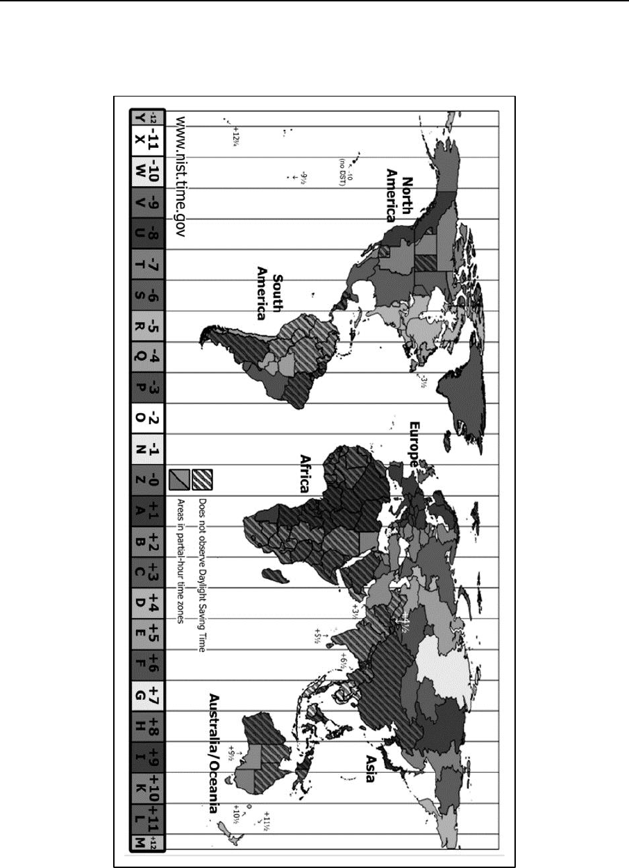
Appendix E
E-2 ATP 6-02.70 31 December 2015
E-7. Many countries use military time as their main time format. European, African, Asian, and Latin
American countries commonly use military time as their main time format. In some countries, both the 12
and 24-hour clock are used. Figure E-1 shows the world map and military zone designators for each zone.
Figure E-1. World military time zone designator chart
Military Time Zone Designators
31 December 2015 ATP 6-02.70 E-3
E-8. Table E-1 outlines each time zone around the world and provides its relationship to Zulu time.
Table E-1. Example of world time zone conversion (standard time)
Military Time Zone Designators
Y
X
W
V
U
T
S
R
Q
P
O
N
Z
A
B
C
D
E
F
G
H
I
K
L
M
Civilian Time Zones
IDLW
NT
HST
ASDT
PST
MST
CST
EST
AST
NST
AT
WAT
UTC
CET
EET
BT
ZP4
ZP5
ZP6
WAST
CCT
JST
GST
SBT
IDLE
1
2
0
0
1
3
0
0
1
4
0
0
1
5
0
0
1
6
0
0
1
7
0
0
1
8
0
0
1
9
0
0
**
2
0
0
0
2
1
0
0
2
2
0
0
2
3
0
0
2
4
0
0
0
1
0
0
0
2
0
0
0
3
0
0
0
4
0
0
0
5
0
0
0
6
0
0
0
7
0
0
0
8
0
0
0
9
0
0
1
0
0
0
1
1
0
0
1
2
0
0
*
Standard Time=Universal Time + Value from Table
Z
0
E
+5
K
+10
P
-3
U
-8
A
+1
F
+6
L
+11
Q
-4
V
-9
B
+2
G
+7
M
+12
R
-5
W
-10
C
+3
H
+8
N
-1
S
-6
X
-11
D
+4
I
+9
O
-2
T
-7
Y
-12
* =Today ** =Yesterday
Legend
ASDT-Alaska Standard Time
EST-Eastern Standard time
PST-Pacific Standard Time
AST-Atlantic Standard Time
GST-Guam Standard Time
SBT-Solomon Island Time
AT-Azores Time
HST-Hawaii Standard Time
UTC-Coordinated Universal Time
AWST-Australian Western Standard Time
IDLE-International Date Line East
WAST-West Africa Time Zone
BT-Baghdad
IDLW-International Date Line West
WAT-West Africa Time
CCT-China Coast Time
JST-Japan Standard Time
ZP-4 Azerbaijan, Oman, Mauritius
CET-Central European Time
MST-Mountain Standard Time
ZP-5 Maldives, Pakistan, Tajikistan
CST-Central Standard Time
NST-Newfoundland Standard Time
ZP-6 Bangladesh, Kazakhstan
EET-Eastern European Time
NT-Nome Time
This page intentionally left blank.

31 December 2015 ATP 6-02.70 Glossary-1
Glossary
The glossary lists acronyms and terms with Army or joint definitions. Where Army and
joint definitions differ, (Army) precedes the definition. The proponent publication for
terms is listed in parentheses after the definition. This publication is not the proponent
for any terms.
SECTION I – ACRONYMS AND ABBREVIATIONS
ACES
automated communications engineering software
AESOP
Afloat Electromagnetic Spectrum Operations Program
CEMA
cyber electromagnetic activities
CJCSM
Chairman of the Joint Chiefs of Staff manual
CJSMPT
Coalition Joint Spectrum Management Planning Tool
COA
course of action
COMSEC
communications security
COP
common operational picture
CSV
comma separated values
DA
Department of the Army
DD
Department of Defense
DOD
Department of Defense
EA
electronic attack
EP
electronic protection
EMI
electromagnetic interference
EMOE
electromagnetic operational environment
EW
electronic warfare
EWO
electronic warfare officer
G-2
assistant chief of staff for intelligence
G-3
assistant chief of staff, operations
G-6
assistant chief of staff, signal
G-7
assistant chief of staff, information engagement
GEMSIS
Global Electromagnetic Spectrum Information System
GHz
gigahertz
HERF
hazards of electromagnetic radiation to fuels
HERO
hazards of electromagnetic radiation to ordnance
HERP
hazards of electromagnetic radion to personnel
HN
host nation
HNSWDO
Host Nation Spectrum Worldwide Database Online
Hz
Hertz
J-3
operations directorate of a joint staff
J-6
communications system directorate of a joint staff
JACS
joint automated communications electronics operation instructions system
JCEOI
joint communications-electronics operating instructions

Glossary
Glossary-2 ATP 6-02.70 31 December 2015
JFMO
joint frequency management office
JRFL
joint restricted frequency list
JSC
joint spectrum center
JSIR
joint spectrum interference resolution
JSIRO
joint spectrum interference resolution online
JSME
joint spectrum management element
kHz
kilohertz
MANCAT
multi spectral ambient noise collection and analysis tool
MCEB
Military Communications-Electronics Board
MDMP
military decisionmaking process
MHz
megahertz
NCE
network-centric environment
NG
National Guard
NIPRNET
Nonsecure Internet Protocol Router Network
NTIA
National Telecommunicatoins and Information Administration
OPLAN
operation plan
OPORD
operation order
RF
radio frequency
S-2
battalion or brigade intelligence staff officer
S-3
battalion or brigade operations staff officer
S-6
(Army) battalion or brigade signal staff officer
S2AS
Spectrum Situational Awareness System
SDD
spectrum dependent devices
SFAF
standard frequency action format
SINCGARS
single-channel ground and airborne radio system
SIPRNET
SECRET Internet Protocol Rourter Network
SMO
spectrum management operations
SOI
signal operating instructions
SPEED
systems planning, enginnering, and evaluation device
SSRF
standard spectrum resource format
XML
extensible markup language
SECTION II – TERMS
cyber electromagnetic activities
Activities leveraged to seize, retain, and exploit an advantage over adversaries and enemies in both
cyberspace and the electromagnetic spectrum, while simultaneously denying and degrading adversary
and enemy use of the same, and protecting the mission command system. (ADRP 3-0)
direction finding
(joint) A procedure for obtaining bearings of radio frequency emitters by using a highly directional
antenna and a display unit on an intercept receiver or ancillary equipment. (JP 1-02)
electromagnetic environmental effects
(joint) The impact of the electromagnetic environment upon the operational capability of military forces,
equipment, systems, and platforms. Also called E3 (JP 1-02)

Glossary
31 December 2015 ATP 6-02.70 Glossary-3
electromagnetic interference
(joint) Any electromagnetic disturbance, induced intentionally or unintentionally, that interrupts,
obstructs, or otherwise degrades or limits the effective performance of electronics and electrical
equipment. Also called EMI (JP 1-02)
electromagnetic operational environment
(joint) The background electromagnetic environment and the friendly, neutral, and adversarial
electromagnetic order of battle within the electromagnetic area of influence associated with a given
operational area. Also called EMOE. (JP 6-01)
electromagnetic spectrum
(joint) The range of frequencies of electromagnetic radiation from zero to infinity. It is divided into 26
alphabetically designated bands. Also called EMS. (JP 1-02)
electromagnetic spectrum control
(joint) Coordinated execution of joint electromagnetic spectrum operations with other lethal and
nonlethal operations that enable freedom of action in the electromagnetic operational environment (JP
3-13.1)
electromagnetic spectrum management
(joint) Planning, coordinating, and managing joint use of the electromagnetic spectrum through
operational, engineering, and administrative procedures. (JP 6-01)
electronic warfare
(joint) Military action involving the use of electromagnetic and directed energy to control the
electromagnetic spectrum or to attack the enemy. Also called EW. (JP 3-13.1)
electronic attack
(joint) Division of electronic warfare involving the use of electromagnetic energy, directed energy, or
antiradiation weapons to attack personnel, facilities, or equipment with the intent of degrading,
neutralizing, or destroying enemy combat capability and is considered a form of fires. Also called EA.
(JP 3-13.1)
electronic protection
(joint) Division of electronic warfare involving actions taken to protect personnel, facilities, and
equipment from any effects of friendly or enemy use of the electromagnetic spectrum that degrade,
neutralize, or destroy friendly combat capability. Also called electronic protection. (JP 3-13.1)
electronic warfare support
(joint) Division of electronic warfare involving actions tasked by, or under the direct control of, an
operational commander to search for, intercept, identify, and locate or localize sources of intentional and
unintentional radiated electromagnetic energy for the purpose of immediate threat recognition, targeting,
planning, and conduct of future operations. Also called ES. (JP 3-13.1)
frequency allocation
An entry in the table of frequency allocations of a given frequency band for the purpose of its use by one
or more terrestrial or space radiocommunication services or the radio astronomy service under specified
conditions. This term shall also be applied to the frequency band concerned. (NTIA Redbook)
frequency allotment
An entry of a designated frequency channel in an agreed plan, adopted by a competent conference, for
use by one or more administrations for a terrestrial or space radiocommunication service in one or more
identified countries or geographical areas and under specified conditions. (NTIA Redbook)
frequency assignment
The authorization given by an administration for a radio station to use a radio frequency or radio
frequency channel under specified conditions. (NTIA Redbook)

Glossary
Glossary-4 ATP 6-02.70 31 December 2015
frequency deconfliction
(joint) A systematic management procedure to coordinate the use of the electromagnetic spectrum for
operations, communications, and intelligence functions. Frequency deconfliction is one element of
electromagnetic spectrum management. (JP 1-02)
frequency proposal
(joint) A proposed frequency assignment which is in the approval process (upon approval it becomes a
frequency assignment). (MCEB Pub 8)
guarded frequencies
(joint) A list of time-oriented, enemy frequencies that are currently being exploited for combat
information and intelligence or jammed after the commander has weighed the potential operational gain
against the loss of the technical information. (JP 1-02)
host nation
(joint) A nation which receives the forces, supplies of allied nations or North Atlantic Treaty
Organization organizations to be located on, to operate in, or to transit through its territory. Also called
HN. (JP 1-02)
joint electromagnetic spectrum operations
(joint) Those activities consisting of electronic warfare and joint electromagnetic spectrum management
operations used to exploit, attack, protect, and manage the electromagnetic operational environment to
achieve the commander’s objectives. Also called JEMSO. (JP 1-02.)
joint restricted frequency list
(joint) A time and geographically oriented listing of TABOO, PROTECTED, and GUARDED
functions, nets, and frequencies and limited to the minimum number of frequencies necessary for
friendly forces to accomplish objectives. Also called JRFL. (JP 1-02)
joint spectrum interference resolution
(joint) is a process designed to mitigate or define the procedures to mitigate Electromagnetic interference
(EMI) that regularly hampers the mission command of military or non-military operations by degrading
essential systems that use the electromagnetic spectrum. Since EMI can be caused by enemy, neutral,
friendly, or natural sources, it generally must be resolved on a case-by-case basis. The intent of the JSIR
procedures (CJCSM 3320.02D) is to mitigate EMI incidents at the lowest possible level within the
command structure. However, when the cause and recipient of the interference are not within the same
component force or supporting element, resolution may require assistance from the combatant command,
joint task force (JTF), Service Spectrum Management Headquarters or higher levels of authority. Also
called JSIR. (MCEB Pub 8)
military decisionmaking process
An interactive planning methodology to understand the situation and mission, develop a courses of
action, and produce an operation plan or order. (ADP 5-0)
protected frequencies
(joint) Friendly, generally time-oriented, frequencies used for a particular operation, identified and
protected to prevent them from being inadvertently jammed by friendly forces while active electronic
warfare operations are directed against hostile forces. (JP 1-02)
spectrum management operations
The interrelated functions of spectrum mangement, frequency assignment, host nation coordination, and
policy that together enable the planning, management, and execution of operations within the
electromagnetic operational environment during all phases of military operations. Also called SMO. (FM
6-02)
standard frequency action format
(joint) used for DOD radio frequency proposals, assignments, modifications, renewals, reviews, and
deletions. Will be replaced by the standard spectrum resource format. Also called SFAF. (MCEB Pub 7)

Glossary
31 December 2015 ATP 6-02.70 Glossary-5
standard spectrum resource format
(joint) is a format for exchanging data related to spectrum management within the DOD. Will replace
the Standard Frequency Action Format. Also called SSRF. (MCEB Pub 8)
TABOO frequencies
(joint) Any friendly frequency of such importance that it must never be deliberately jammed or
interfered with by friendly forces including international distress, safety, and controller frequencies.
(JP 1-02)
unified action partners
Those military forces, governmental and nongovernmental organizations, and elements of the private
sector with whom Army forces plan, coordinate, synchronize, and integrate during the conduct of
operations. (ADRP 3-0)
warfighting function
A group of tasks and systems (people, organizations, information, and processes) united by a common
purpose that commanders use to accomplish missions and training objectives. (ADRP 3-0)
This page intentionally left blank.

31 December 2015 ATP 6-02.70 References-1
References
REQUIRED PUBLICATIONS
Most joint publications are available online: www.dtic.mil/doctrine/new_pubs/jointpub.htm.
These documents must be available to intended users of this publication.
ADRP 1-02. Terms and Military Symbols. 7 December 2015.
JP 1-02. Department of Defense Dictionary of Military and Associated Terms. 8 November 2010.
RELATED PUBLICATIONS
These documents contain relevant supplemental information.
JOINT PUBLICATIONS
Most joint publications are available online: http://www.dtic.mil/doctrine.
CJCSM 3320.01C. Joint Electromagnetic Spectrum Management Operations in the Electromagnetic
Operational Environment. 14 December 2012.
CJCSM 3320.02D. Joint Spectrum Interference Resolution (JSIR) Procedures. 3 June 2013.
JP 3-13.1. Electronic Warfare. 8 February 2012.
JP 3-28. Defense Support of Civil Authorities. 31 July 2013
JP 6-01. Joint Electromagnetic Spectrum Management Operations. 20 March 2012.
MCEB Pub 7. Standard Frequency Action Format (SFAF). 20 November 2012.
MCEB Pub 8. Standard Spectrum Resource Format (SSRF). 4 April 2012.
ARMY PUBLICATIONS
Most Army doctrinal publications and regulations are available online: http://www.apd.army.mil.
ADP 3-0. Unified Land Operation. 10 October 2011.
ADP 5-0. The Operations Process. 17 May 2012.
ADRP 3-0. Unified Land Operations. 16 May 2012.
ADRP 3-28. Defense Support of Civil Authorities. 14 June 2013.
AR 5-12. Army Use of the Electromagnetic Spectrum. 15 February 2013.
AR 380-5. Department of the Army Information Security Program. 29 September 2000.
ATP 3-36. Electronic Warfare. 16 December 2014.
FM 3-38. Cyber Electromagnetic Activities. 12 February 2014.
FM 6-0. Commander and Staff Organization and Operations. 05 May 2014.
FM 6-02. Signal Support to Operations. 22 January 2014.
FM 27-10. The Law of Land Warfare. 18 July 1956.
OTHER PUBLICATIONS
National Telecommunications and Information Administration Redbook. Manual of Regulations and
Procedures for Federal Radio Frequency Management. May 2013 found online at the
following; http://www.ntia.doc.gov/osmhome/redbook/redbook.html.
Title 10 of the United States Code. Armed Forces.
Title 32 of the United States Code. National Defense.
Title 47 of the United States Code. Telecommunication.
http://uscode.house.gov/.

References
Reference-2 ATP 6-02.70 31 December 2015
International Telecommunication Union Radio Regulations. Edition of 2008.
PRESCRIBED FORMS
None.
REFERENCED FORMS
Unless otherwise indicated, DA Forms are available on the Army Publishing Directorate (ADP)
website: www.apd.army.mil.
DA Form 2028. Recommended Changes to Publications and Blank Forms.
DD Forms are available on the Office of the Secretary of Defense (OSD) web site:
www.dtic.mil/whs/directives/infomgt/forms/formsprogram.htm.
DD Form 1494. Application for Equipment Frequency Allocation.
WEBSITES
Acquisition Community Connection.
https://acc.dau.mil/CommunityBrowser.aspx?id=18002&lang=en-US.
Spectrum XXI overview. http://www.disa.mil/jsc/pdf/SPECTRUMXXI_JSC.pdf.

31 December 2015 ATP 6-02.70 Index-1
Index
Entries are by paragraph number unless indicated otherwise.
A
Afloat Electromagnetic
Spectrum Operations
Program (AESOP), 5-27–5-
29
automated communications
engineering software, 5-49
B
bandwidth, 5-6, 5-21, 5-29, D-8
battlefield, 2-2, B-4, D-48
C
call signs, 5-56, D-18, D-26
call words, D-26
Coalition Joint Spectrum
Management Planning Tool
(CJSMPT), 5-16–5-24
collaboration, 1-10, 1-18, 1-4,
5-23, 5-61, A-4, A-18
combatant commander, 5-38,
D-22
common operational picture
(COP), 2-26, A-9
COMSEC, 5-49, 5-50, 5-52, D-
24, D-28
course of action (COA), 1-5, 2-
22, 2-25,A-10
cyber electromagnetic activities
(CEMA), 1-11, 1-17, 2-11–2-
19, A-30–A-34
D
data call, 2-6, 2-25, A-18, A-21,
D-3, D-5
DD Form 1494, 2-21, 5-30, A-
5, A-17
domestic operations, 4-12, 4-
13, 4-16,
deconfliction, 1-27, 2-8, 2-10,
3-9, 5-39, A-11, B-4, D-32
E
electromagnetic operational
environment (EMOE), 1-9, 1-
10
electromagnetic spectrum
(EMS), 1-1–1-5, 1-9–1-11, 1-
14
electronic warfare (EW), 1-24,
2-15, 3-12
F
Fires, 3-3, 3-4
frequency assignment, 1-14, 5-
37, 5-43, A-18, A-23
frequency deconfliction, 1-27,
2-8, 2-10, 3-9, 5-39, A-11, B-
4, D-32
frequency proposal, A-3, A-18
G
Global Electromagnetic
Spectrum Information
System (GEMSIS), 5-7, 5-
14–5-16
guarded frequencies, D-31
H
hazard of electromagnetic
radiation to fuels, 3-7
hazard of electromagnetic
radiation to ordnance, 3-6
hazard of electromagnetic
radiation to personnel, 3-5
Hopset,1-14, 5-57
host nation (HN), 1-14, 1-22, 1-
23
Host Nation Spectrum
Worldwide Database Online
(HNSWDO), 1-23, 5-48, 5-
65, A-18
I
Intelligence, 3-2,
interference, 1-5–1-7, , 1-30, 5-
38, 5-38, 5-61, A-4, D-34–D-
38, D-40–D-42, D-47–D-50
J
joint communications-
electronics operating
instructions (JCEOI), 2-25,
4-3, 5-6, A-13, A-18, B-4, D-
19–D-24
joint frequency management
office (JFMO), 4-1–4-4, 5-23
joint restricted frequency list
(JRFL), 2-3, 3-1, 3-4, 5-6, A-
6, A-7, B-4
joint spectrum interference
resolution (JSIR), 5-21, 5-35,
A-4, A-18
joint spectrum interference
resolution online (JSIRO), 5-
61, A-4, A-18
joint spectrum management
element (JSME), 4-1, 4-3, 5-
6
L
lifecycle, D-1
Lockouts, 5-57
M
MANCAT, 5-5–5-7, 5-9, 5-12
Military Communications
Electronics Board (MCEB),
1-14, 2-21, 5-35, A-12, A-18,
B-4
military decisionmaking
process (MDMP), 2-21–2-
25, A-8
mission command, 1-11,1-13,
3-1, 3-10, 3-11, A-9 A-18
Movement and Maneuver, 3-1
N
National Guard, 4-11, 4-16, 4-
17
Network-Centric Environment
(NCE), A-7, B-2, B-4
P
protected frequencies, D-31
R
repository, 5-18, 5-20, 5-23, 5-
24, 5-32, A-18, D-36, D-38
S
satellite, 1-26, 2-3, 5-6, 5-7, 5-
12, 5-26, 5-42, 5-59, A-13,
A-18
signal operating instructions
(SOI), 2-4, 2-49–2-51, 5-56,
A-18, B-4
spectrum management, 1-9, 2-
4, 4-12, 4-13, 5-14, D-1–D-6,
D-13–D-16
Spectrum Situational
Awareness System (S2AS),
5-5, 5-7–5-13
Spectrum XXI, 5-4, 5-12, 5-14,
5-18, 5-20, 5-31–5-36, B-2

Index
Reference-2 ATP 6-02.70 31 December 2015
Standard Frequency Action
Format (SFAF), 4-15, 5-4, 5-
20, 5-25, 5-26, A-6, A-18, B-
4
standard spectrum resource
format (SSRF), 5-20, 5-26 A-
3, A-6, A-18, B-4
Sustainment, 3-9
Systems Planning,
Engineering, and Evaluation
Device (SPEED), 5-14, 5-25,
5-27
T
taboo frequencies, 2-25, D-31
U
unified action partners, 1-8, 2-2
unified land operations, 1-11,
1-12, 1-15–1-17
USNORTHCOM, 4-12, 4-17
USPACOM, 4-12
W
warfighting function,1-4, 2-2, 3-
1, 3-2–3-4, 3-9, 3-10

By Order of the Secretary of the Army:
MARK A. MILLEY
General, United States Army
Chief of Staff
Official:
GERALD B. O’KEEFE
Administrative Assistant to the
Secretary of the Army
1535501
DISTRIBUTION:
Active Army, Army National Guard, and United States Army Reserve: Distributed in electronic media
only (EMO).
ATP
6-
02.70
31 December 2015
PIN: 105928-000
