
MTR 04W0000048
MITRE TECHNICAL REPORT
Spectrum 101
An Introduction to Spectrum Management
March 2004
John A. Stine
David L. Portigal
Sponsor: OASD NII Spectrum Policy
Directorate
Contract No.: DAAB07-03-C-N206
Dept. No.: W805 Project No.: 0704C550-CA
Approved for Public Release;
Distribution Unlimited.
©2004 The MITRE Corporation
Washington C3 Center
McLean, Virginia
Approved for Public Release; Distribution Unlimited
Case # 04-0423
Foreword
Each day the military relies on spectrum-dependent technologies to complete its
missions. New technologies found in radars, sensors, satellites, radios, and wireless devices
make information superiority a reality and are an integral part of military operations. The
effectiveness of ships at sea, soldiers in the field, and planes in the sky depend on the
capabilities of these systems. In turn, the capabilities of these systems are dependent on the
unseen resource of spectrum.
In the past, the availability of this unseen resource was a minor issue for the DoD, as
there was ample spectrum access to meet its needs. However, today, new technologies, the
needs of other users (government and commercial), and the proliferation of wireless
technologies worldwide have made maintaining even current spectrum allocations difficult.
New, exciting wireless communication products are creating a large demand for spectrum.
Wireless subscriber services are growing rapidly worldwide. Emerging countries, in an
effort to modernize, are choosing to deploy wireless infrastructure in lieu of wired
infrastructure since it costs less. All of these factors make a more competitive environment
for worldwide spectrum access.
As the recent operations in Afghanistan and Iraq can attest, the DoD achieves much of its
military capability from exploiting technology, especially information technology. Military
capability is dependent on spectrum availability and the current military transformation will
make it more dependent in the future. Unless the DoD manages spectrum smartly it will
forfeit its potential capability. This document provides a broad background of the issues in
spectrum management so that personnel who work in DoD spectrum management
organizations, members of government and DoD who make decisions affecting the allocation
and allotment of spectrum, and DoD program managers who oversee the development of
spectrum-dependent systems can better grasp the complexity of spectrum management and
their role in protecting military access to spectrum and developing and acquiring systems that
use it efficiently. This document provides a repository of basic concepts that are relevant to
these tasks so that players in spectrum management activities can perform these functions
most effectively.
Transformation of the military to enable the vision of “Network Centric Warfare”
promises more effective and efficient use of military force. This transformation will not be
possible without adequate spectrum access to support it.
iii
Preface
This paper has been written to provide an introduction to Spectrum Management with a
DoD perspective. It assumes an audience that is unfamiliar with radio communications
theory, with the current allocation and use of spectrum, and with the processes involved in
managing spectrum. Therefore, it begins by providing an introduction to basic concepts in
radio communications theory in order to build the novice’s intuition so that he might
subsequently understand the rationale for the current allocations and the methods for
managing spectrum. It attempts to give a historical record of how these processes and
allocations came to be. It describes the current spectrum management process to include the
major players and the procedures they use to make decisions. Finally, it gives a brief
introduction to some new technologies that are being introduced and their ramifications on
the spectrum management process. Thus, this paper has been written as both a tutorial and a
basic reference for new players in the spectrum management business.
Use of this document does not require a sequential reading. Each section is reasonably
self-contained. The key concepts of each section are summarized in its introduction and
conclusion. If the reader feels reasonably confident that he understands the concepts as laid
out in these two subsections, then he has sufficient knowledge to undertake the rest of the
report. The body of each section provides greater depth into the material. If the material
becomes so challenging that the reader is not likely to gain from reading it, we recommend
that the reader just skip to the next subsection and continue from there. The concepts in this
paper are presented in a descriptive way and thus do not rely on the reader’s grasp of the
preceding concepts.
v
Table of Contents
Section Page
1. The Basics: What is Spectrum? 1-1
1.1 Signals 1-1
1.2 Modulation 1-3
1.2.1 Sinewave Modulation 1-4
1.2.2 Pulse Modulation 1-7
1.3 Frequency Content and Bandwidth 1-9
1.3.1 Frequency Content of Modulated Sine Waves 1-9
1.3.2 Frequency Content of Pulses 1-10
1.3.3 Signal Multiplexing 1-11
1.3.4 Spectrum Capacity 1-11
1.4 Transmission, Propagation, and Reception 1-12
1.4.1 Spreading and Attenuation 1-13
1.4.2 Absorption 1-14
1.4.3 Reflection 1-14
1.4.4 Diffraction 1-14
1.4.5 Refraction 1-15
1.4.6 Interference 1-16
1.4.7 Harmonic and Intermodulation Distortion 1-18
1.5 Transmission Power 1-21
1.5.1 Noise 1-22
1.5.2 Signal to Noise Ratio 1-22
1.5.3 The Decibel 1-23
1.5.4 Other Decibel Units 1-24
1.6 Time of Transmission 1-25
1.7 Frequency 1-27
1.7.1 Effect on Electronics 1-28
1.7.2 Effect on Antennas 1-28
1.7.3 Effect on Propagation 1-29
1.8 Summary 1-31
2. The History of Regulation 2-1
2.1 The Birth of Regulation 2-1
2.2 The Birth of Spectrum Management 2-2
2.3 The Communications Act of 1934 2-4
2.4 Maturing of International Regulation 2-5
vii
2.5 The Formation of the National Telecommunications and Information
Administration (NTIA) 2-6
2.6 Summary 2-6
3. The Basics: Spectrum Allocation 3-1
3.1 The Traditional Administrative Approach to Spectrum Management 3-1
3.2 Definitions (As Defined by the ITU Radio Regulations) 3-2
3.3 United States Frequency Allocations 3-2
3.4 Determining Allocations 3-8
4. Department of Defense Use of Spectrum and Threats to that Use 4-1
4.1 DoD Capabilities Derived from Use of Spectrum 4-1
4.2 Some Salient Factors 4-2
4.3 System Tradeoffs 4-4
4.4 Spectrum Losses and Restrictions 4-5
4.4.1 Low Power Unlicensed Devices 4-5
4.4.2 General Considerations 4-6
4.4.3 Some Specific Cases of Spectrum Loss 4-7
4.4.4 Ultra Wideband 4-9
4.4.5 Public Sector Challenges 4-10
4.4.6 Government Coexistence Challenges 4-10
4.5 Maintenance of Spectrum Capability 4-11
4.6 DoD Use of Spectrum in the United States and its Possessions (US&P) 4-11
4.6.1 Test and Training 4-11
4.6.2 Posts, Camps, Stations, and Ports 4-13
4.6.3 Military Operations 4-14
4.6.4 Coordination with Neighboring Countries 4-14
4.7 DoD Use of Spectrum Outside the US&P 4-15
4.7.1 Host Nation Support 4-15
4.7.2 International Spectrum Supportability 4-15
4.8 Summary 4-16
5. Spectrum Management Organizations and U.S. Participation in World
Radiocommunication Conferences 5-1
5.1 International Spectrum Management 5-1
5.2 National Spectrum Management 5-4
5.2.1 The National Telecommunications and Information Administration (NTIA) 5-4
5.2.2 The Federal Communications Commision (FCC) 5-7
5.3 International Negotiation 5-9
5.3.1 The Department of State Organization that Handles International
Communications Issues 5-9
5.3.2 Procedures for WRC Participation 5-10
viii
5.4 Impact of the Dual Management Scheme 5-12
5.5 Summary 5-13
6. Spectrum Management within the Department of Defense 6-1
6.1 DoD Spectrum Management Organizations 6-1
6.2 DoD Spectrum Management Planning Processes 6-3
6.2.1 Strategic Planning 6-4
6.2.2 Planning for Spectrum Supportabilty 6-7
6.2.3 Operational Planning 6-14
6.3 DoD Spectrum Operations (Assignments) 6-15
6.3.1 Continental United States (CONUS) 6-15
6.3.2 OCONUS Permanent/Fixed 6-16
6.3.3 Battlespace Spectrum Management (BSM) 6-16
6.4 DoD Spectrum Management Systems and Tools 6-18
6.4.1 Spectrum Management and Supportability Tools 6-18
6.4.2 Overarching Spectrum Architecture 6-20
6.5 Summary 6-20
7. Technological Advances and their Impact on Spectrum Management 7-1
7.1 Information Efficient Technologies 7-1
7.1.1 Source Coding 7-2
7.1.2 Redundancy Reduction 7-2
7.1.3 Data Compression 7-2
7.1.4 Error Correction 7-3
7.2 Spectrum Efficient Technologies 7-4
7.2.1 Advanced Modulation 7-4
7.2.2 Pulse Shaping 7-4
7.2.3 Receiver Capability 7-5
7.2.4 Tradeoffs 7-6
7.3 Digital Signal Processing Technology 7-6
7.3.1 Identifying Frequency Content 7-7
7.3.2 Software-Defined Radio 7-8
7.4 Spatial Reuse Technologies 7-8
7.4.1 Directional Antennas 7-8
7.4.2 Networking 7-9
7.4.3 Spread Spectrum Communications 7-11
7.4.4 Signal Polarization 7-14
7.4.5 Smart Antennas 7-14
7.5 Dynamic Spectrum Management 7-17
7.5.1 Spectrum Mining 7-17
7.5.2 Dynamic Channel Assignment 7-18
7.6 Alternative Perspectives on Efficient Spectrum Management 7-20
ix
7.7 Summary 7-21
8. Real World Constraints in Spectrum Management 8-1
8.1 Legacy Allocations 8-1
8.2 Legacy Equipment 8-2
8.3 Desirable Features of Spectrum Assignments 8-2
8.4 Transition Issues 8-3
8.5 Changing Spectrum Use 8-3
8.6 Conclusion 8-4
List of References RE-1
Appendix A. DoD Spectrum Use A-1
Appendix B. Department of Defense Electromagnetic Spectrum Management Plan B-1
Glossary GL-1
Acronyms B-1
Terms B-8
x
List of Figures
Figure Page
1-1. Representations of a 40kHz sine wave 1-2
1-2. Representation of a 400 Hz square wave 1-4
1-3. Example of a sine wave information signal modulating a higher frequency sine
wave carrier 1-5
1-4. Example modulation of a digital signal 1-6
1-5. Pulse types 1-7
1-6. Pulse modulation methods 1-8
1-7. Frequency content of AM modulated signals 1-9
1-8. Frequency content of a rectangular pulse as a function of its dimensions 1-10
1-9. Frequency content of a rectangular pulse for baseband and sine wave pulses 1-11
1-10. Example of using different carrier frequencies to multiplex multiple signals on
the same media 1-11
1-11. The transmission and reception of EM radiation 1-13
1-12. Reflection of an electromagnetic wave 1-14
1-13. Diffraction of a wave around a building 1-15
1-14. Wave refraction (propagation is slower in Medium 2 than in Medium 1) 1-16
1-15. Multipath interference 1-17
xi
1-16. Cross band interference 1-18
1-17. Outputs of the non-linear mixing of two input signals at frequencies f
1
and f
2
1-19
1-18. Antenna end of a typical receiver or transmitter 1-20
1-19. Intermodulation distortion at a receiver 1-21
1-20. Effect of noise on a detected signal in the time domain 1-22
1-21. Signal and noise in the frequency domain 1-23
1-22. EM signal absorption by atmospheric gases 1-30
3-1. Spectrum allocation 3-3
3-2. Allocation of spectrum to federal government and non-federal government use
as a percentage of bandwidth 3-6
3-3. Percentage of total number of assignments and licenses found in each band
6
3-7
3-4. Percentage of total number of assignments to each federal government function
by band
6
3-8
3-5. Example frequency allocation entries in the ITU-R Radio Regulations and the
NTIA Red Book 3-9
5-1. Organization of the ITU 5-2
5-2. Spectrum use regions 5-3
5-3. Organization of the NTIA 5-4
5-4. Organization of the NTIA Office of Spectrum Management 5-5
xii
5-5. FCC organization chart 5-8
6-1. Organizations that cooperatively manage DoD spectrum 6-3
6-2. Organization to study allocation issues for WRCs 6-7
6-3. Proposed alignment of spectrum supportability activities and spectrum
certification stages with the defense acquisition management framework 6-10
6-4. The spectrum certification process 6-12
7-1. Comparison of the spectral content of pulses that change gradually vs. rapidly.
The pulse in the time domain is shown on the left and their use of spectrum is
shown on the right. 7-5
7-2. Comparison of omni-directional and directional antenna coverage. 7-9
7-3. Effect of pulse width on spectral content. The shorter pulse width τ
2
spreads the
spectrum further than the τ pulse width. 7-12
7-4. Example of Direct Sequence Spread Spectrum (DSSS) 7-13
7-5. Anti-jam characteristics of DSSS 7-13
7-6. An example of constructive and destructive interference from two signals that
are transmitted in phase from two adjacent antennas based on direction of
propagation. 7-15
7-7. Differences in received signals caused by multipath arrival of signals at the
receiving antennas 7-16
7-8. Graph of the Erlang C formula showing the benefit of statistically multiplexing
channels to support randomly arriving traffic 7-18
7-9. A notional layout of members of a military formation showing subscription to
multicast groups 7-20
xiii
List of Tables
Table Page
1-1. The International Telecommunications Union – Radiocommunication sector band
designations 1-26
1-2. Letter designations for radar frequency bands (IEEE Std 521 – 2002) 1-27
3-1. Frequency bands where government has exclusive primary status 3-5
3-2. Frequency bands where the government is the exclusive user 3-5
5-1. AAG frequency assignment bands 5-6
6-1. DD Form 1494 submission lead time guidelines from AFI 33-120 6-13
6-2. FAA frequencies and bands 6-16
xiv
Section 1
The Basics: What is Spectrum?
The pervasive presence of commercial radio, wireless telephony, television, Global
Positioning Systems (GPSs), Doppler weather RADAR, and other wireless technologies
provides the average individual with the intuition of the goal of spectrum management.
Multiple radiated signals can be engineered to coexist in the same physical space and then be
selectively detected by using the appropriate equipment and channel. The objective of
spectrum management is to enable the optimum number and types of services to coexist.
Radio signals are able to coexist in the same physical space on account of the ability to
isolate signals by using the physical characteristics of their transmissions. One of these
characteristics is spectrum. Radio frequency spectrum is the continuum of frequencies of
electromagnetic radiation from 9,000 Hz (9 kilohertz) to 300,000,000,000 Hz (300
gigahertz). In the simplest sense, one may isolate multiple users of spectrum by allocating
different bands of this continuum to them.
Spectrum management, however, is much more complicated than simply allocating
frequencies. It is desirable and necessary to reuse spectrum. Thus, other physical
characteristics of transmissions are also used to isolate spectrum users. Spectrum
management is the oversight of all characteristics of electromagnetic radiation. The goal is
to prevent users from harmful interference while allowing the optimum use of the spectrum.
The problem is complex since the characteristics of electromagnetic radiation vary with time,
space, and frequency.
This section provides a simplified description of the process by which information is
modulated onto a signal and then transmitted and received. It explains basic concepts of
signals, frequency, modulation, bandwidth, propagation, and reception to provide the reader
with a technical foundation to understand the approaches that are used to manage spectrum.
1.1 Signals
A signal is broadly defined as a detectable quantity (e.g., current, voltage,
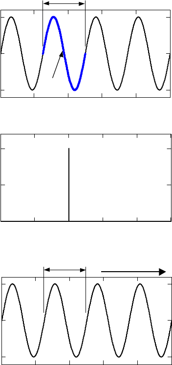
electromagnetic field) that varies in time. An important signal for radio communications is
one where the quantity varies as a periodic sine wave as depicted in Figure 1-1a. This signal
is presented in the time domain, that is, the quantity is shown to change with time. The
horizontal axis is time and the vertical axis is the value of the changing quantity, such as
voltage. As illustrated on the drawing, the portion of the signal that repeats itself is called a
cycle, and the time between repetitions is its period.
1-
1
0.02 0.04 0.06 0.08 0.10
t (msec)
A
-A
A
f (kHz)
612
18
24 300
d (kilometers)
20 40
60
80 1000
1 cycle
Period (T)
Wavelength (λ)
a. Time domain representation
b. Frequency domain representation
c. Wave propagation representation
Velocity, V = 3 · 10
8
m/sec
Propagation direction
A
-A
AmplitudeAmplitudeAmplitude
Figure 1-1. Representations of a 40kHz sine wave
Frequency is the number of cycles that occur in one second and is defined in units of Hertz,
which is another name for cycle per second. The frequency of a signal is the reciprocal of its
period. The amplitude of the signal is half the peak-to-peak separation of the quantity that is
changing with time, e.g., voltage.
A second way of presenting signals is in the frequency domain. Figure 1-1b presents this
same sine wave in the frequency domain. A pure sine wave appears as a single line in the
1-
2
frequency domain. Note that the horizontal axis has units of Hz and that the vertical axis has
the units of the changing quantity. The position of the line on the horizontal axis
corresponds to the signal’s frequency and the height of the line corresponds to the signal’s
amplitude. This is the domain that frequency spectrum is understood and managed.
A wave is a signal that exists in space and varies with time and location. We say that
waves propagate through space. If the signal is a wave, then there is still a third way to
present this signal and it looks very similar to the first, see Figure 1-1c. It is a depiction of
the signal’s propagation. Distance units rather than time calibrate the horizontal axis. The
significance of this depiction is that it provides the understanding for wavelength. It is the
distance that separates the start of each cycle. A signal’s wavelength is the product of a
signal’s period and the velocity of its propagation. An observer that remains stationary in a
space through which a wave propagates will observe the varying quantity in the time domain.
Table 1-1 lists frequencies and their corresponding wavelengths.
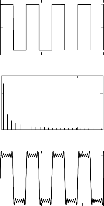
Any variation to a sine wave will add additional frequency content. A classic method to
illustrate this fact is to observe the frequency content of a square wave. We provide this
example to show that practical signals contain multiple frequencies simultaneously and that a
reasonable replication of the signal can be made with a subset of those frequencies. In
Figure 1-2a we illustrate a 400 Hz square wave. As illustrated in Figure 1-2b, this square
wave has infinite frequency content with the magnitude of each frequency component
decreasing with frequency. (Each of the lines corresponds to a pure sine wave.) It is
undesirable to transmit signals with large frequency content, and they will frequently be
filtered so that only a restricted subset of the frequency content is transmitted. In
Figure 1-2c, we show a reconstructed square wave signal that only includes the frequency
content beneath 5000 Hz. For practical purposes the square wave can be recognized.
Another example demonstrating that frequency content can be lost is seen in sound
reproduction. The human ear, generally, can detect signals between 20 Hz and 20 kHz.
However, a smaller range of the frequency content of sound will not render it unintelligible.
For example, a telephone reproduces sound with frequencies as high as 3 kHz, a commercial
AM radio station reproduces sound up to 5 kHz, and a commercial FM station reproduces
sound with frequencies up to 15 kHz. All are intelligible although there is a definite
difference in fidelity.
1.2 Modulation
Modulation is the process of transferring information onto electromagnetic radiation for
the purpose of information transmission. There are two general types: In the first,
information is transferred onto a continuous sine wave, in the second, pulses are used.
1-
3
050001
.
10
4
1.5
.
10
4
2
.
10
4
f
0 0.002 0.004 0.006 0.008 0.01
t
0 0.002 0.004 0.006 0.008 0.01
t
a. Time domain representation
b. Frequency domain representation
c. Square wave reproduction using frequency
components beneath 5 kHz
Amplitude
Amplitude
Amplitude
Figure 1-2. Representation of a 400 Hz square wave
1.2.1 Sinewave Modulation
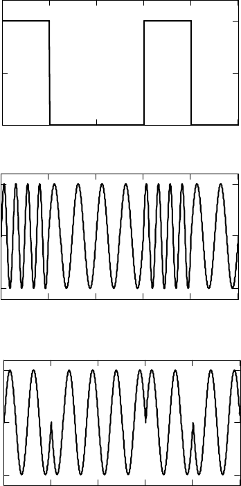
Sine wave modulation is accomplished by changing one of the descriptive parameters of
the sine wave: amplitude, frequency, phase, or time of transmission. In Figure 1-3, we show
an information signal impressed onto a sine wave (a.k.a. sine wave carrier) as an amplitude-
modulated signal and as a frequency-modulated signal. We do not show a phase-modulated
signal for this continuous information signal since it would not be distinguishable from the
FM signal when displayed in this one-dimensional plot. However, if the information signal
1-
4

0 0.002 0.004 0.006 0.008 0.01
t
0 0.002 0.004 0.006 0.008 0.01
t
0 0.002 0.004 0.006 0.008 0.01
0
t
a. Information signal
b. Amplitude modulated signal
c. Frequency modulated signal
Amplitude
AmplitudeAmplitude
Figure 1-3. Example of a sine wave information signal modulating a higher frequency
sine wave carrier
is discrete as in a digital signal, there is a very definite difference in how the modulated
signal looks. In Figure 1-4, we show a digital signal that modulates a carrier using the
frequency and phase
1-
5
0 0.002 0.004 0.006 0.008 0.01
0
0.5
1
t
0 0.002 0.004 0.006 0.008 0.01
t
0 0.002 0.004 0.006 0.008 0.01
0
t
a. Digital information signal
b. Frequency modulated digital signal
aka Frequency shift keying
c. Phase modulated digital signal
aka Phase shift keying
Amplitude
AmplitudeAmplitude
Figure 1-4. Example modulation of a digital signal
characteristics. In this figure we show that a bit of information is associated with each signal
state, as defined by its frequency in Figure 1-4b and by its phase in Figure 1-4c. Modulation
of digital signals can be more complex where the signal can assume multiple different states,
and each state is defined by the combination of its frequency, amplitude, and phase. Each
state of such a signal can represent multiple bits of information rather than just the one bit as
shown. For example, each state of a signal with eight states can represent three bits. The
word “symbol” is frequently used to refer to both the signal state and the combination of bits
that each state represents. Much effort is invested in designing these multiple state signals
since they provide the opportunity to increase the information-carrying capacity of the signal.
1-
6
Note that there are engineering tradeoffs since these designs require more sophisticated
radios and are more susceptible to the effects of adverse environmental conditions.
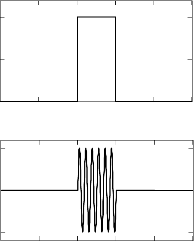
1.2.2 Pulse Modulation
A pulse consists of a short burst of radiation. These pulses may be a simple increase in
the electromagnetic field (referred to as baseband, meaning there is no sinusoidal waveform
during the pulse) or a short burst of a sinusoidal wave. Figure 1-5 illustrates the difference
between the two types of pulses. The type of burst and the frequency of the sinusoidal wave
will determine what part of the spectrum the signal uses. Details follow in the next section.
Information is modulated onto the pulses by changing their characteristics. The most
common characteristics used follow:
Pulse amplitude: The amplitude of a pulse within a prescribed time slot is proportional to a
characteristic of the information (e.g., amplitude is proportional to the amplitude of an analog
signal, a.k.a. pulse amplitude modulation [PAM]).
Pulse duration: The width of the pulse is proportional to a characteristic of the information
(e.g. duration is proportional to the amplitude of an analog signal, a.k.a. Pulse width
modulation [PWM]).
a. Baseband pulse
b. Sine wave pulse
t
t
Amplitude
Amplitude
Figure 1-5. Pulse types
1-
7
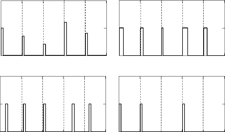
Pulse position: The position of a pulse within a prescribed time slot is proportional to a
characteristic of the information (e.g., position is proportional to the amplitude of an analog
signal, a.k.a. Pulse Position Modulation [PPM]).
Pulse occurrence: The presence of a pulse in a particular time slot provides the information
(e.g., time slots may correspond to bits and the presence of a pulse may correspond to a
particular value of that bit). Another use for the presence of a pulse is to indicate the relative
change in an analog signal, a.k.a. Pulse Code Modulation (PCM).
Figure 1-6 illustrates the different types of pulse modulation. Pulse type emissions were
used in the earliest communications systems. The first radio invented by Marconi used
baseband pulses. The initial advances in communications were to use sinusoidal pulses.
Pulses are also especially useful in radar applications. Radar systems send pulses and then
wait for an echo from a target. Ultra wideband communications and radars are based on the
use of pulses.
a. Pulse amplitude
b. Pulse duration
c. Pulse position
d. Pulse occurrence
tt
tt
AmplitudeAmplitude
Amplitude
Amplitude
Figure 1-6. Pulse modulation methods
1-
8
1.3 Frequency Content and Bandwidth
1.3.1 Frequency Content of Modulated Sine Waves
The frequency content of the modulated signal consists of the carrier component and the
upper and lower bands of frequencies associated with the frequency content of the
information. In Figure 1-7, we illustrate the frequency content of the AM modulated signal.
Its content consists of the carrier component and the carrier plus and minus the information
frequency content. An AM signal requires spectrum bandwidth equal to twice that of the
information signal. FM modulated signals and digital signals will also have bands of
frequency content on both sides of a carrier, but the size of these sidebands is generally
larger. Their size depends on how much the frequency is allowed to change in the FM signal
and how rapidly signals are shifted in digital communications. As an example, a commercial
AM station has a bandwidth of 10 kHz, a commercial FM station has a bandwidth of 200
kHz, and a commercial television station has a bandwidth of 6 MHz. A highly efficient form
of AM modulation is single sideband modulation where one of the sidebands of an AM
signal is isolated from the carrier and the other sideband prior to transmission. Its bandwidth
is that of the frequency content of the information signal.
0 2000 4000 6000 8000
f
f
c
f
c
-W
f
c
+W
a. Frequency content of the AM signal
illustrated in Figure 1-3b
b. Frequency content of a typical AM signal
where W is the bandwidth of the information
AmplitudeAmplitude
Figure 1-7. Frequency content of AM modulated signals
1-
9
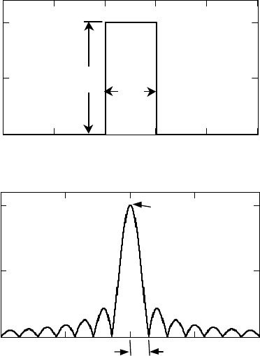
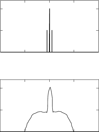
1.3.2 Frequency Content of Pulses
The spectral content of a pulse is a function of its duration, shape, and amplitude. A well
understood pulse is the rectangular pulse. Figure 1-8 illustrates the relation of the breadth of
its frequency content to the dimensions of the pulse. We see that the shorter the pulse, the
wider and lower the spectral content. Figure 1-9 illustrates the difference in frequency
content of a baseband pulse and a sine wave pulse.
T
A
t
AT
T
-1
f
a. A pulse in the time domain
b. Spectral content of a pulse
Amplitude
Amplitude
Figure 1-8. Frequency content of a rectangular pulse as a function of its dimensions
1-
10
a. Baseband pulse: Spectral content starts
at 0 Hz
b. Sine wave pulse: Spectral content centered
at the frequency of the sine wave
f
f
Frequency of the
sine wave
0
Amplitude
Amplitude
Figure 1-9. Frequency content of a rectangular pulse for baseband and sine wave
pulses
1.3.3 Signal Multiplexing
Multiple modulated signals can coexist in the same medium by separating their carrier
frequencies so that their sidebands do not overlap. See Figure 1-10. In Section 7 we
describe modulation techniques that allow multiple signals to occupy the same spectrum
simultaneously.
f
Figure 1-10. Example of using different carrier frequencies to multiplex multiple
signals on the same media
1.3.4 Spectrum Capacity
As described, bandwidth is a measure of the breadth of spectrum that is used to provide a
service. The amount of information that can be sent in a signal is proportional to its
bandwidth. A well known formula that expresses the limit of capacity for digital signals is
provided by the Shannon–Hartley Theorem:
1-
11
(
)
2
log 1CBW SNR=+
where C = channel capacity (b/s)
BW = bandwidth (Hz)
SNR = signal-to-noise power ratio
This formula shows that capacity is also dependent on Signal-to-Noise (SNR). (See Section
1.5.2.) High bandwidth and high power signals will have more capacity than lower
bandwidth and lower power signals. These factors become tradeoffs in the design of
communications systems. For reasons we will explain in Section 1.7.1, higher bandwidth
signals are usually sent at higher frequencies.
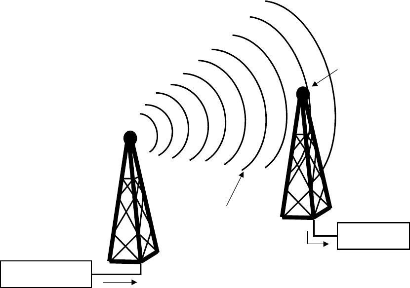
1.4 Transmission, Propagation, and Reception
A radio transmits a signal by driving a current on an antenna where the current amplitude
is the changing quantity of the signal. This changing current, in turn, induces an
electromagnetic field about itself, with a field strength that corresponds to the current
amplitude. This electromagnetic field propagates away from the antenna as a wave at the
speed of light. As the signal propagates, it attenuates. At a distant receiver, the
electromagnetic wave passes across the receiver’s antenna and induces a current.
Figure 1-11 illustrates this process. Note that all electromagnetic radiation in the area will
pass across the receiving antenna. In order for the receiver to detect the correct signal, it
must be able to isolate the desired signal from all others. If the receiver is in range of two
transmitters using the same frequency band that it is trying to receive, then the receiver may
not be able to properly capture the desired signal for demodulation and what it does capture
may be unintelligible. The spectrum management process attempts to prevent this situation
from occurring. The goal is not to prevent transmitters from using the same frequencies but
to ensure that receivers are capable of receiving and distinguishing the desired signals. So
there may be more than one transmitter using the same carrier frequency as long as the
receivers are able to distinguish the desired signal over the others.
1-
12
Transmitter
Current to
the antenna
Induced field
from antenna
current
EM Wave
Propagation
Receiver
Current from
the antenna
Induced current
from changing
EM field
Figure 1-11. The transmission and reception of EM radiation
Terrain, atmosphere, and other factors can affect propagation. Sections 1.4.1 through
1.4.5 describe the basic propagation phenomena that affect signal strength. These
phenomena illustrate exactly how complex signal propagation can be, especially in terrestrial
environments. Reception at an antenna depends on a signal’s strength and the presence of
other signals at the receiver. Sections 1.4.6 and 1.4.7 discuss interference and some of the
unintentional sources of interference that may come from authorized users of spectrum.
1.4.1 Spreading and Attenuation
Spreading and attenuation are the reductions of signal strength that occur as a result of
the distance propagated. Spreading is the loss that occurs due to the geometric dispersion of
the signal. For example, consider a signal that propagates spherically. If we consider the
signal power for each concentric sphere to be the same, the strength per unit area decreases
as the sphere gets larger. Attenuation is the reduction of signal strength that results from
propagating through media.
1-
13

1.4.2 Absorption
All material media through which signals propagate (e.g. air, glass, water, etc.) consists
of atoms and molecules. As an electromagnetic wave passes through such a medium, energy
is transferred from the wave to the atoms and molecules of the medium. Once absorbed by
the medium, the energy is lost forever.
1.4.3 Reflection
Reflection occurs when a wave strikes the boundary of two media and some or all of the
wave’s energy does not enter the new medium. The wave returns to and continues to
propagate in the first medium although usually in a different direction. Figure 1-12
illustrates electromagnetic wave reflection.
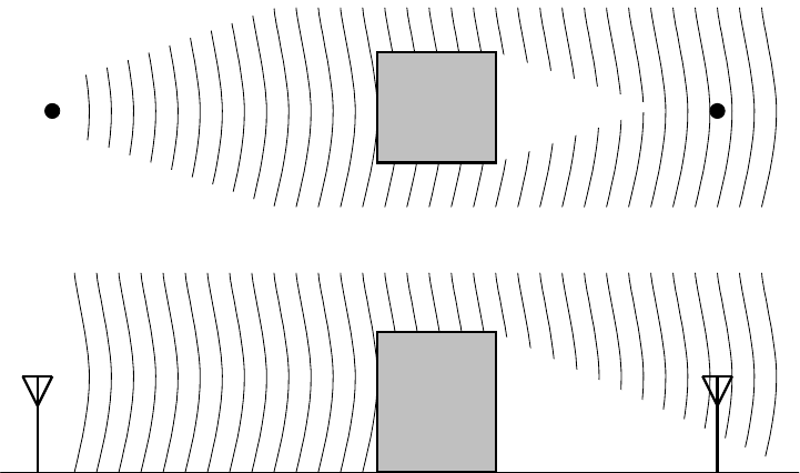
1.4.4 Diffraction
Diffraction is the phenomenon that allows electromagnetic waves traveling in a straight
path to reach behind obstacles. The principle that governs this behavior is referred to as
Huygens’ principle. Huygens’ principle states that every point on a spherical wavefront can
be considered a source of a secondary wavefront. This principle explains how a signal can
be received behind a large obstacle such as a mountain or a large building. Figure 1-13
illustrates diffraction around a building. The portion of the area behind these obstacles that
the secondary wave does not reach is called the shadow zone. The effect of moving in and
out of shadow zones on account of mobility is referred to as slow fading.
Incident wave
Reflected wave
Angle of
incidence
Angle of
reflection
Reflecting surface
Figure 1-12. Reflection of an electromagnetic wave
1-
14
Shadow zone
Shadow
zone
b. Side view
a. Top view
Figure 1-13. Diffraction of a wave around a building
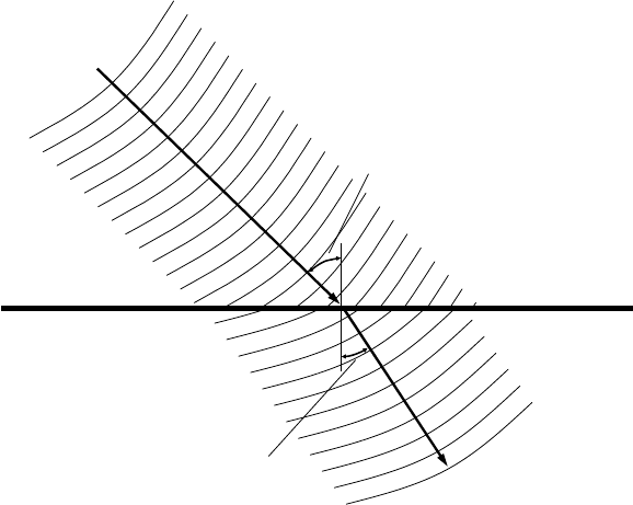
1.4.5 Refraction
Refraction can be thought of as the bending of the direction of propagation of an
electromagnetic wave. Refraction occurs because of changes in wave velocity that are
caused by differences in the properties of media through which it propagates.. Figure 1-14
illustrates a refracted wave. In this example, the velocity is higher in medium one than
medium two. The portion of the wave front that enters the new medium first will change
velocities before the rest of the wave. Thus, it will travel a different distance than the portion
of the wave in the old medium resulting in the redirection of the wave front. In any specific
medium, the velocity of an electromagnetic wave is inversely proportional to its density.
Since the earth’s atmosphere has different densities at different elevations, signals that are
sent toward the sky at an appropriate angle will refract back toward the earth’s surface.
Similarly, signals directed toward earth may be refracted back toward the sky.
1-
15
Medium 1
Medium 2
Angle of
incidence
Angle of
refraction
Figure 1-14. Wave refraction (propagation is slower in Medium 2 than in Medium 1)
Refraction may also occur in the ionosphere where the different electron densities cause
the refraction. The ionosphere is created by the ultraviolet radiation from the sun interacting
with the atmospheric gases. At higher elevation a greater percentage of the gases are
ionized, but since the density of gases is lower, the highest density of ions is not at the top of
the ionosphere. A wave propagating toward the sky will first start to bend back toward the
earth; however, if the wave passes the point of highest density it will bend back the other
way.
1.4.6 Interference
Interference occurs when multiple electromagnetic waves in the same spectrum are
coincident in space. When two or more waves meet at a receiver’s antenna, the resulting
detected signal is the linear superposition of the incident waves (i.e., The signals are added to
each other). Such colliding can degrade the quality of the signal a receiver detects.
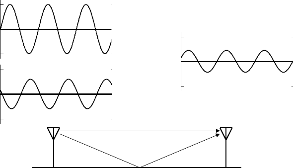
Interference can be generated by other transmitters or by multiple versions of the same signal
that have arrived at a receiver along different paths. For example, reflected signals can
interfere with signals that propagated on a direct line of site. This type of self-interference
will occur more frequently as there are more surfaces off of which a signal can reflect. For
this reason, terrestrial transmitters have less range than identical transmitters at higher
altitudes. Figure 1-15 illustrates an example of the destructive interference that may occur
on account of this phenomenon. This type of interference is referred to as multipath
interference. The effect of moving in and out of such interference zones is referred to as fast
fading.
1-
16
Direct line of sight
Reflected
0
0
Reflected
signal
Detected
signal
=
Direct
signal
+
Figure 1-15. Multipath interference
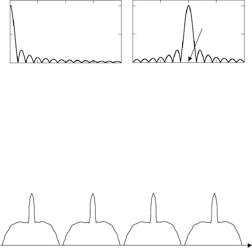
Interference may occur between signals in adjacent frequency bands. We use Figure
1-16 to illustrate the issues. In Figure 1-16a we show the ideal case where a receiver detects
two adjacent signals each arriving with the same power. This could happen if both
transmitters use the same power. and the path losses to the receiver are the same. (Path loss
is the energy lost in the signal due to propagation and the environment. We discuss this
further later in this section.) The receivers then isolate the specified band of the desired
signal. The power of the desired signal is substantially higher than that of the sidebands of
the adjacent signal and is easily received. In Figure 1-16b we show what happens when the
receiver is closer to the adjacent band transmitter. In this example, the location gives the
adjacent transmitter a 10x advantage. (This example exaggerates the sideband amplitude but
in real systems the differences in received strength on account of different path loss can be
greater than 100,000x.) The power in its sidebands prevents reception of the desired signal.
Regulations place demands on how much radiation may occur in the sidebands but even then
other measures are taken to mitigate this interference. For example, a channel normally
separates television stations in the same market. A proposal for increasing spectrum
efficiency is to collocate transmitters so that the relative strengths of their signals are the
same to all receivers. Thus, adjacent channels may be used in the same market. This may
only be practical for broadcast services.
1-
17

a. Signals on adjacent bands received with the same power
b. Signals on adjacent bands where the adjacent signal has a 10x power advantage
Received channel
Received channel
Desired signal
Desired signal
Detected signal
Interfering
signal
Interfering
signal
Amplitude
Amplitude
Amplitude
Amplitude
f
f
Detected signal
f
f
Desired signal
Figure 1-16. Cross band interference
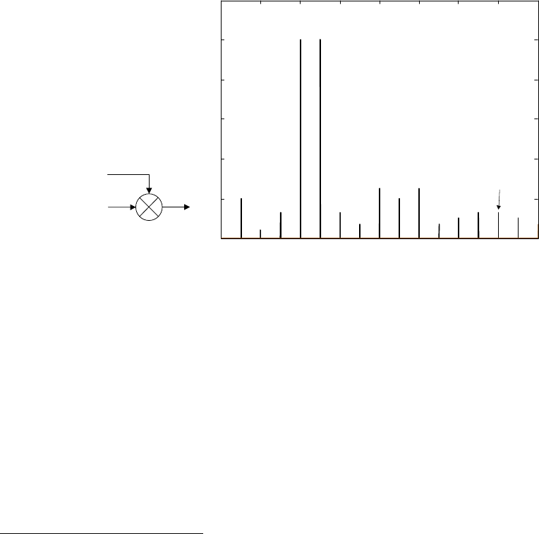
1.4.7 Harmonic and Intermodulation Distortion
A well-known phenomenon that occurs in communications systems is the multiplication
and mixing of signal frequencies in non-linear components of the system. This
multiplication and mixing leads to interference to and from other systems that is not obvious
from the basic system design. Figure 1-17 illustrates the phenomenon. In this example, the
outputs after mixing the two signals in the non-linear device are additional signals at
frequencies that are harmonics of the input signals (i.e., integer products of the original
signal frequencies,
or ) and intermodulation products of the input signals (i.e., sums
and differences of integer multiples of the original signal frequencies,
). Such
mixing can involve more than two input signals and the outputs can occur across a vast range
of the spectrum. Harmonic distortion is the name given to the interference that comes from
the harmonic outputs. Intermodulation (IM) distortion is the name given to the interference
that comes from the IM outputs. Generally, the amplitudes of harmonic and IM products are
11
nf
22
nf
11 2 2
nf nf±
1-
18
much less than the input signals and decrease as the order
1
of the product increases.
Receivers can receive over a large dynamic range of signal strengths so IM products from
neighboring transmitters can interfere with the reception of a weaker signal from a distant
transmitter.
IM can occur at receivers, transmitters, or external to the radios. Receiver IM (RIM) and
transmitter IM (TIM) occur because there are non-linear devices within these components.
External IM (EIM) occurs since signals mix in unintentional non-linear devices such as
antennas or cables.
f
2
f
1
f
1
f
2
2f
2
2f
1
3f
1
4f
1
3f
2
f
2
-
f
1
2f
2
-
f
1
2f
1
-
f
2
f
1
+
f
2
2f
1
+
f
2
f
1
+
2f
2
3f
1
-
f
2
3f
2
-
f
1
3f
1
-
2f
2
Frequency
Amplitude
Figure 1-17. Outputs of the non-linear mixing of two input signals at frequencies
f
1
and f
2
Figure 1-17 attempts to show the spread of harmonic and intermodulation products. The
relative amplitude of the products will differ depending on the characteristics of the mixer.
In radios, filters may be added to help eliminate these unwanted outputs.
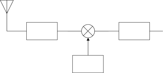
Mixer circuits and non-linear amplifiers are common components in receivers and
transmitters. Figure 1-18 illustrates the antenna end of typical receivers and transmitters. As
illustrated, they deliberately include a non-linear mixer circuit. Additionally, the radio
frequency (RF) amplifier may also be non-linear as non-linear amplifiers are less expensive
1
Product order is the sum of the coefficients of the input frequencies so in the example of Figure 1-17 where
there are two inputs the product order m is determined by
12
mn n
=
+ .)
1-
19
to make and to operate. The significance of this type of transceiver design is that harmonic
and IM distortion can be created inside transceivers both prior to transmission and after
reception.
Local
Oscillator
RF
Amplifiers
IF
Amplifiers
...
f
LO
Figure 1-18. Antenna end of a typical receiver or transmitter
The purposes of the blocks are as follows. The RF amplifier operates on signals in the
range of frequencies that the radio is designed to receive or transmit. The intermediate
frequency (IF) section operates at a frequency that does not change. The local oscillator
generates a sinusoidal signal. This type of radio design enables the radio to operate over a
range of channels. Mixing an incoming RF signal with a local oscillator frequency in a
receiver allows the higher frequency RF signal to be down-converted to a lower IF where the
bulk of the signal amplification and processing is accomplished. In a transmitter, the
opposite occurs where the mixer circuit up-converts the IF signal to a higher frequency RF
signal. In this design, the channel is selected by selecting the local oscillator frequency, i.e.,
RF = f
LO
– IF or RF = f
LO
+ IF.
The role of the RF section in a transmitter is to isolate the desired signal from the mixer
circuit and to amplify it for transmission. The role of the RF section in a receiver is to isolate
the received signal and to preamplify it prior to mixing. In transceivers, the RF filters that
isolate the signals for transmission and reception are different blocks.
In reception, it is possible that two received RF channels can be mixed and then both
enter the IF section, i.e., RF
1
where IF = f
LO
– RF
1
and RF
2
where IF = f
LO
+ RF
2
. The
interfering RF signal’s frequency is called the image frequency. The range of local oscillator
frequencies and the IF are selected, and filters are designed at the RF and IF sections with the
intent of preventing IM products from leaving the radio or an image frequency from entering
the IF section.
The prices of receivers and transmitters increase with the quality of the RF components.
In order to keep prices of radios and televisions at an affordable price for consumers,
especially in the early days of their use, frequency assignments were made in a way to
minimize the occurrence of intermodulation distortion in receivers. Now that spectrum is
1-
20

becoming more scarce, many experts propose that regulation be used to mandate better
quality receivers so more channels can be used in the same market.
EIM is a major contributor to co-site interference. Two transmitters that operate close to
each other can transmit IM products due to the mixing of signals at one of the transmitters’
antennas. A receiver operated close to two or more transmitters may receive an IM signal
from those transmitters possibly mixed in its own antenna. Figure 1-19 is an example. The
exact device that causes IM can be very difficult to predict and to prevent. Frequency
assignment is frequently used to help prevent IM distortion. A well-known case of the use of
assignment to prevent IM distortion is to avoid making television assignments on channel 32.
The third harmonic of channel 32 interferes with the signals used by the Global Positioning
Satellite system.
Victim
Receiver
Channel 94
Interfering
Transmitter
Channel 102
Interfering
Transmitter
Channel 98
Figure 1-19. Intermodulation distortion at a receiver
1.5 Transmission Power
Transmission power determines the strength of the electromagnetic (EM) field that
radiates from an antenna and the range that the signal can propagate and still be received.
Since it is desirable to reuse spectrum, the spectrum management process will also regulate
the strength of signal emissions. Restricting the power of transmission limits the coverage of
the transmission; thus, reducing the interference it causes and enabling more reuse of the
spectrum.
1-
21
A receiver is able to receive a signal so long as it is stronger than noise and other
interfering signals. The following subsections provide a more in-depth discussion of noise
and the measures to quantify the relative strength of signals.
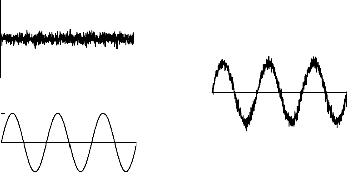
1.5.1 Noise
Noise is defined as the unwanted electrical energy in a receiver’s band of reception. This
noise can be further reduced into two types: correlated and uncorrelated. Correlated noise
comes about as a result of distortion of the signal by radio components. Uncorrelated noise,
the noise we are interested in, is noise that is present regardless of whether there is a signal
present. This noise can be caused by natural phenomenal from the atmosphere, the cosmos,
the sun, heat, the operation of man made devices such as motors or other transmitters, and
noise introduced by the circuitry of receivers. Noise is present in all portions of the spectrum
and is generally modeled as being random and as having the same amplitude across the
spectrum. Much of this noise is unavoidable. Figure 1-20 illustrates what noise may look
like in the time domain and how it would affect a detected signal.
Detected
signal
=
Noise
Signal
+
Figure 1-20. Effect of noise on a detected signal in the time domain
1.5.2 Signal to Noise Ratio
Signal to noise ratio is a simple mathematical relationship of the signal level with respect
to the noise level. It is normally expressed as either a ratio of voltages or powers using units
of decibels. Figure 1-21 illustrates the detected signal with noise in the frequency domain. If
the signal strength is substantially larger than the noise, i.e., has a large SNR, then the
receiver can detect the signal. If the signal power is low with respect to the noise, then it
cannot be received, despite amplification at the receiver. The specific quantity that is
considered a high SNR will vary based on the modulation that is used and the quality of the
1-
22

receiver. However, in many applications, an SNR of 10 decibels is considered a minimum
for reliable performance.
Signal
Noise
Figure 1-21. Signal and noise in the frequency domain
1.5.3 The Decibel
The decibel unit was created to explain acoustic phenomena. Telephone engineers in the
1920s needed a measure to express sound levels. Typically, changes in air pressure
associated with sound are measured in micro Pascals (µPa). However, the average human
can detect signals as low as 20 µPa and as large as 200,000,000 µPa. This very large range
of values makes µPa an ineffective measure. Additionally, in perception, differences in
sound are perceived as relative changes rather than linear changes. A change in sound from
100 to 1000 µPa is perceived just as the change from 1000 to 10000 µPa. So the engineers
decided to base the new unit on the ratio of sound levels and used the logarithm base 10 as its
fundamental unit. They called this unit a Bel, naming it after Alexander Graham Bell, the
inventor of the telephone. Subsequently, they divided the Bel into the 10 parts now called
decibels since a decibel was about the minimum change in sound pressure that a human can
detect. The abbreviation for decibel, dB, has a capital B since a Bel was derived from
Alexander Graham Bell’s last name.
A decibel has two major characteristics: first, it is a ratio of power and second, it is based
on a base 10 logarithm. To make this clearer, we provide two examples of how decibels are
calculated. Say you have an amplifier that will increase the power of an incoming signal
from P
1
to P
2
. Say the signal entering the amplifier has a power of 1 mWatt, and the output
has a power of 100 mWatts. The amplification in decibels would be calculated as follows
()
2
10 10
1
10 log 10 log 100 20 dB.
P
P
⎛⎞
×=×=
⎜⎟
⎝⎠
1-
23

Say an electromagnetic field is measured at a point very close to its source antenna and found
to be 10,000 times stronger than it is at some destination. Then the path loss would be
calculated as follows
10
1
10 log 40 dB.
10,000
⎛⎞
×=−
⎜⎟
⎝⎠
Using the decibel unit greatly simplifies the math involved in calculating the total
changes in signal power in a system. Contributions of individual components and
phenomena can be added rather than multiplied. The challenge is that when one is not
accustomed to using logarithms it is difficult to get an appreciation of the magnitude of
changes. Two numbers are useful, 10 and 3. A signal’s power increases 10 times for 10 dB
and 2 times for 3 dB and decreases by 1/10 times for –10 dB and ½ for –3 dB. Say there is a
power change of 86 dB. The relative power change can be calculated as follows
8
8
80 dB 10 10 10 10 10 10 10 10 10
6 dB 2 2 4
86 dB 4 10 .
=×××××××=
=×=
=×
1.5.4 Other Decibel Units
A decibel is a unit in the same sense that a “percent” is a unit. It only has a physical
meaning when there is a reference value. Frequently, it is necessary to provide units for an
actual quantity, such as the strength of a signal or the effectiveness of an antenna. In these
cases, the dB scale is retained but modified by a reference to a specific value. We describe
some of the more popular measures below.
dBm: Power relative to 1 mW. A 100 mW signal is also a 20 dBm signal.
dBW: Power relative to 1 W. A 100mW signal is also a –10 dBW signal. dBm units can
be converted into dBW units by subtracting 30 dB.
dBi: Gain of an antenna with respect to an isotropic antenna, an antenna that transmits with
the same power in all directions. The dBi measure would be used to express the advantage
that is gained by using an antenna with some directionality. It expresses the ratio of
transmitted power in the preferred direction of that antenna as compared to what would be
transmitted in that same direction if the antenna were isotropic where both antennas are
excited by the same power.
dBd: Gain of an antenna with respect to a half-wave dipole antenna. A half-wave dipole
antenna, also referred to as a Hertz antenna, consists of two equidistant wires that extend
from the feed point out ¼ wavelength for a total of ½ wavelength end-to-end. The reference
power is measured in the preferred direction of the dipole, which is perpendicular to the
elements. The value for dBd is measured in the same manner as dBi. A dipole antenna has a
1-
24
gain of 2.4 dBi. A dBd measure can be converted to a dBi measure and vice versa by adding
or subtracting 2.4 dB respectively.
dBc: The power of a signal referenced to a carrier signal, i.e., if a second harmonic signal at
10 GHz is 3 dB lower than a fundamental signal at 5 GHz, then the signal at 10 GHz is -3
dBc. These units are used to describe in decibels how far down signals and noise are relative
to a known signal.
dBr: A relative power relation between a measured power strength and a suitable reference
signal's power strength. It indicates difference as opposed to actual power strength. When
used, the reference is usually identified.
dBsm: A unit used in conjunction with radar cross sections. It measures the power of a
reflected radar signal from an object relative to the power that would be reflected from a
reference of a copper sphere with a 1 meter square cross sectional area.
dB SPL: A unit of sound pressure that is used to specify the loudness of a sound. The
acronym SPL stands for sound pressure level and the reference (0dB SPL) is 0.0002
dyne/cm
2
, the threshold of what humans can hear. 70 dB SPL is the level of an average
conversation
1.6 Time of Transmission
Time is relevant to the spectrum management problem in two ways. First of all, multiple
users can use the same spectrum by using it at different times. Second, propagation
characteristics can change in time.
When stations do not use a band of frequencies continuously, those frequencies can then
be shared with other users. Time can be used as a parameter to allocate usage.
Propagation characteristics can change in time. These changes often happen on a
periodic basis being driven by some phenomenon. Day-night, seasonal and even sunspot
cycles can affect propagation phenomena. For example, these cycles will affect the electron
concentrations in the ionosphere thus affecting the height at which the ionosphere refracts
signals and the signal frequencies that can be refracted.
1-
25

Table 1-1. The International Telecommunications Union – Radiocommunication sector band designations
Band Designation
Frequency range
a
Wavelength
b
Overall
Utilization
Antenna
Gains
Propagation
Modes
Coverage Susceptibility Predict-
ability
2
ELF (extremely low
frequency)
30 – 300 Hz
10,000 –
1,000 km
3 VF (voice frequencies) 300 – 3000 Hz 1,000 – 100 km
4
VLF (very low
frequency)
3 – 30 kHz 100 – 10 km High Low
Groundwave,
skywave
Up to
5000 nmi
Noise, skywave
multipath
High
5 LF (low frequency) 30 – 300 kHz 10 – 1 km High Low
Groundwave,
skywave
Up to
1000 nmi
Noise, skywave
multipath
High
6
MF (medium
frequency)
300 – 3 000 kHz 1 km – 100 m High Low
Groundwave,
skywave
Up to
1000 nmi
Noise, skywave
multipath
Medium
7 HF (high frequency) 3 – 30 MHz 100 – 10 m High Low-Med
Groundwave,
skywave
Worldwide
Noise, ionospheric
activity
Low
8
VHF (very high
frequency)
30 – 300 MHz 10 – 1 m
Med
–
High
Low-Med Freespace
Line-of-
Sight (LOS)
Terrain multipath High
9
UHF (ultra high
frequency)
300 – 3000 MHz 1m – 10 cm
Med
–
High
Low-High Freespace LOS Terrain multipath High
10
SHF (super high
frequency)
3 – 30 GHz 10 – 1 cm Medium
Med-
Very high
Freespace LOS
Weather, terrain
multipath
Medium
11
EHF (extremely high
frequency)
30 – 300 GHz 1 cm – 1 mm Low
High –
Very high
Freespace
Limited
LOS
Weather, gaseous
absorption
Medium
12 300 – 3000 GHz
1 mm – 100 µm
13 3 – 30 THz
100 – 10 µm
14 10 – 300 THz
10 – 1 µm
15 300 – 3000 THz
1 µm – 100 nm
16 3 – 30 PHz 100 – 10 nm
17 30 – 300 PHz 10 – 1 nm
18 300 – 3000 PHz 1 nm – 100 pm
a
10
0
, hertz (Hz) ; 10
3
, kilohertz (kHz); 10
6
, megahertz (MHz) ; 10
9
, gigahertz (GHz) ; 10
12
, terahertz (THz) ; 10
15
, petahertz (PHz) ;
b
10
3
, kilometer (km) ; 10
0
, meter (m) ; 10
-2
, centimeter (cm) ; 10
-3
, millimeter (mm) ; 10
-6
micrometer (µm) ; 10
-9
, nanometer (nm) ; 10
-12
, picometer (pm)
1-
26

1.7 Frequency
Frequency affects the properties of electromagnetic radiation. These effects vary by the
magnitude of the frequency. To simplify the discussion of these effects, bands of frequencies
have been given designations and then properties have been associated with those
designations. There are numerous ways frequency bands have been designated. The
International Telecommunications Bureau Radio Sector designates bands as listed in
Table 1-1. Bands 4 through 11 are the RF bands that they regulate. There are other
approaches to designating frequency bands. During World War II certain radar bands were
given code words so engineers could talk about them without divulging their actual
frequency. They were deliberately non-sequential. Frequently, engineers will still use these
types of designations; however, there is ambiguity as to the exact frequency bands to which
they refer. Over the years, many different references have tried to define these designations,
but they differ. It is at a point where different companies have different designations peculiar
to themselves. From the standpoint of spectrum management, these designations are
obsolete; however, as recently as 2002, the IEEE published a standard for letter designation
of radar-frequency bands. These designations are listed in Table 1-2.
Table 1-2. Letter designations for radar frequency bands (IEEE Std 521 – 2002)
Band Frequency
HF 3 – 30 MHz
VHF 30 – 300 MHz
UHF 300 – 1000 MHz
L 1 – 2 GHz
S 2 – 4 GHz
C 4 – 8 GHz
X 8 – 12 GHz
Ku 12 – 18 GHz
K 18 – 27 GHz
Ka 27 – 40 GHz
V 40 – 75 GHz
W 75 – 110 GHz
mm 110 – 300 GHz
1-
27

The carrier frequency of a signal affects the properties of the equipment used to generate,
transmit, and receive the signal, as well as the propagation properties of electromagnetic
waves. More detail follows on the impact of carrier frequency on electronics, antennas, and
propagation. Different frequencies are best for different applications.
1.7.1 Effect on Electronics
There are three aspects of electronics that are affected by frequency: carrier generation,
signal filtering, and circuit construction. The difficulty of building a stable signal generator
(i.e., the circuit that makes the carrier signal) or of a tight bandpass filter (i.e., the circuit that
isolates a band of frequencies in the spectrum) is proportional to frequency. A ±0.01% drift
in a 1 MHz carrier signal has a variation of 200 Hz, whereas the same drift in a 1 GHz carrier
signal would be 200 kHz—the bandwidth of 20 commercial AM channels or 1 commercial
FM channel. A measure of the quality of a bandpass filter is its Q, which is defined as the
filter’s center frequency divided by its bandwidth.
c
f
Q
B
W
=
A filter that isolates a 10 kHz wide signal at 1 MHz has the same Q as a filter that isolates
a 10 MHz signal at 1 GHz.
Circuit construction is difficult at higher frequencies since components, i.e., wires, come
closer to the wavelength of the signals. At these relative sizes, circuit components can
become antennas and thus interfere with themselves and generate and transmit signals that
interfere with other receivers. At the other end, lower frequencies often require bigger
components, e.g., antennas, making them impractical for mobile applications.
Simply, as the frequency increases, so do the cost and complexity of building the
electronics. Also, it is not generally feasible to build radios that can operate in bands that are
substantially separated in frequency. Some new technologies are changing this, but
currently, most communications systems are designed to work in very specific bands of
frequencies and cannot be moved to others. Reassigning services to other bands will
normally involve replacing the radios currently providing that service.
Finally, systems are generally assigned to operate at higher frequency assignments if they
require greater bandwidths.
1.7.2 Effect on Antennas
There are many nuances associated with antenna design but all designs are frequency
dependent. The gain of antennas and in the case of directional antennas their beamwidth
2
are
2
Beamwidth is the effective angle over which an antenna can receive a signal.
1-
28

dependent on their relative size compared to the wavelength of the signals they are trying to
receive. Higher frequency antennas can be made smaller for an equivalent gain and
beamwidth. High frequency losses (see Section 1.7.3) can be made-up in higher gain
antennas; however, if it is a dish or parabolic antenna, it will also have smaller beamwidth.
Smaller beamwidth can be either an advantage or disadvantage depending on the application.
For example, smaller beamwidths are harder to detect and provide greater directional
resolution in radar applications, but complicate the tracking necessary in aircraft telemetry
3
applications.
1.7.3 Effect on Propagation
In free space, i.e., outside the earth’s atmosphere in a vacuum, RF signals attenuate with
the square of frequency and the square of distance. The difference in signal power of two
signals at different frequencies at the same range can be determined by
2
2
1
f
f
⎛⎞
⎜⎟
⎝⎠
,
where we want to know the relative strength of the signal with frequency f
1
as compared to
the signal with frequency f
2
. For example, at the same range, a 400 MHz signal will be 100
times weaker than a 40 MHz signal. Similarly, the relative strength of a signal after
propagation can be determined by
2
2
1
d
d
⎛⎞
⎜⎟
⎝⎠
,
where we want to know the relative strength of a signal at distance d
1
compared to the
relative strength of this same signal at distance d
2
. For example, a signal will be 100 times
weaker at 10 meters from an antenna than at 1 meter from the antenna. The good news is
that it will only be 4 times weaker at 2 kilometers than at 1 kilometer.
In the atmosphere and near the earth’s surface, there are numerous other effects, all
frequency dependent, that change the range a signal propagates. Below are some of these
effects.
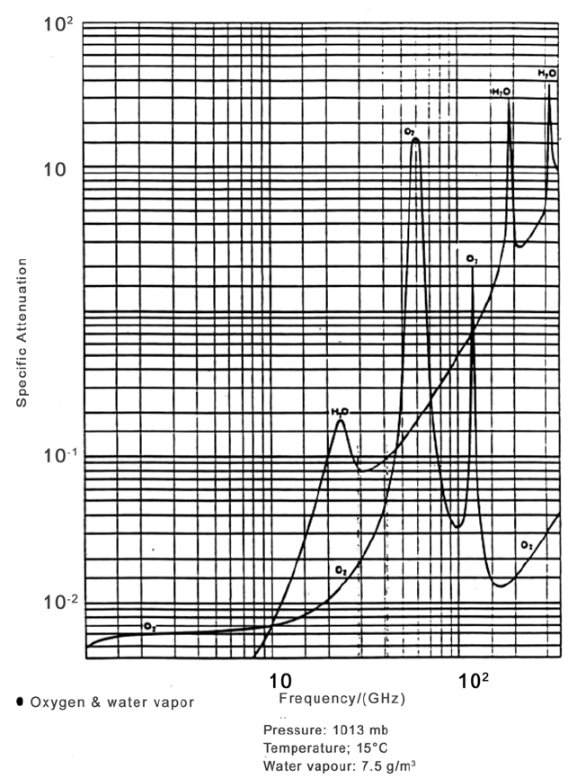
Absorption: Atmospheric gases, i.e., oxygen and water vapor, absorb signals. Figure 1-22
illustrates the specific attenuation that occurs because of this absorption. Again, higher
frequencies attenuate more.
3
Telemetry is the process of transmitting data collected on a remote object to a receiving station.
1-
29
Foliage losses: Foliage scatters and attenuates signals. This type of attenuation increases
with frequency.
Building penetration: Building penetration decreases as frequency increases.
Seawater penetration: Radio waves penetrate seawater at Extremely low Frequency (ELF)
and to some degree at Very Low Frequency (VLF).
Figure 1-22. EM signal absorption by atmospheric gases
1-
30

Ducting: A special condition that causes refraction, i.e., the bending of the wave in the
atmosphere. A skyward signal bends in the atmosphere and is redirected toward the earth
where it is reflected, and the effect repeats itself. This can lead to long range propagation
since there is less spreading of the wave. Ducting does not occur at higher frequencies since
the reflecting surface of the earth appears less smooth and scatters the signal, thus breaking
up the wave. Similarly, at low frequencies the sizes of the ducts will not accommodate the
wavelengths.
Ground wave propagation: Vertically polarized
4
waves at frequencies below 2 MHz can
propagate along the surface of earth. These types of waves induce currents on the earth’s
surface that enable the waves to propagate over the horizon and if conditions are suitable, to
propagate around the world. They propagate best where the earth’s surface conducts best,
like across the ocean. Their propagation is relatively unaffected by changing atmospheric
conditions. Ground waves are frequently used for ship-to-ship and ship-to-shore
communications.
Sky-wave propagation: Signals are reflected or refracted off the earth’s troposphere or
ionosphere allowing greater propagation of signals. This phenomenon affects the high
frequency (HF) band. Specific ranges of the signal depend on which layer of the atmosphere
acts on the signal. This varies with the time of day and some seasonal factors.
Earth-ionosphere waveguide: At frequencies below 30 kHz, both the earth and the
ionosphere behave as conducting mediums. Together they form two spherical shells that
guide waves within. Since electromagnetic waves do not spread out, there is much less
attenuation and thus they can propagate further.
There is a rich diversity in tradeoffs associated with frequency. Although higher
frequencies tend to attenuate more, this attenuation can actually be a feature in a system
where it is desirable to reuse the frequency.
1.8 Summary
In this section, we have provided a brief review of radio communications principles as
they apply to the use o f the RF spectrum. We have demonstrated that management of the
RF spectrum has three components: a frequency component, a spatial component, and a time
component. This provides the basic paradigm for spectrum management. The goal is to
prevent interference among users by separating them in spectrum, separating them in space,
4
Polarization of a radiated wave refers to the direction of the electric field vector of that wave. If the electric
field remains constant in a direction perpendicular to the surface of the earth then it is linearly and
vertically polarized. A long wire antenna that is perpendicular to the earth generates vertically polarized
waves.
1-
31
or separating them in time. We have explained that performance of communications systems
varies by the band of frequencies in which they operate and the physical environment in
which they are employed.
1-
32

Section 2
The History of Regulation
Spectrum management procedures have resulted from a series of needs that arose not
only from technological developments, but from commercial and social pressures. In this
section we provide a brief history of spectrum management that attempts to explain how the
existing spectrum management agencies came into existence and how they function and
interact with each other.
2.1 The Birth of Regulation
The first commercial use of radio, radiotelegraphy, occurred at the beginning of the 20
th
century. Its primary application was in maritime communication, where it was seen as a
significant advance in safe shipping and control of naval vessels. The state-of-the-art,
however, only allowed single use of the spectrum. Intense unregulated competition resulted
in interference, and worse, commercial restrictions on its free use. The Marconi Wireless
Telegraph Company was very aggressive in its efforts to create a monopoly. Its strategy was
to establish shore stations in the principal maritime countries. These stations were prohibited
from handling messages from ships that used equipment of a different manufacturer, thus
creating the incentive for ships to lease Marconi equipment. These ships, in turn, were also
restricted to communicating only with stations using Marconi equipment. Meanwhile, the
Navy was very concerned that it was forced to compete with commercial interests in
establishing communications stations for naval operations. The Navy became the vocal
proponent for national regulation advocating that they be the central authority for regulation.
Early in 1902, Prince Henry of Prussia attempted to send a message from his ship to
President Roosevelt thanking him after a visit to the United States. He was unable to send
the message because a Marconi equipment operator refused to transfer it from Slaby-Arco
equipment. This so infuriated the Prince that he brought the matter to the attention of his
brother, Kaiser Wilhelm. Shortly thereafter, the German government proposed an
international conference to consider an international convention for regulating maritime
communications.
5
This convention was held in August 1903 in Berlin with several European
countries and the U.S., in attendance. The convention ended with a proposed protocol that
would have required all stations to inter-communicate and to accept messages from any ship.
Great Britain and Italy, both in contractual arrangements with Marconi, did not concur, but
all delegates left the convention agreeing to submitting it to their respective governments and
to use it as the basis of a future convention tentatively scheduled for the next year.
5
Users of the German Telefunken equipment had the same restriction on its use as the Marconi equipment
operators.
2-1
The next conference, postponed until 1906 because of the Russo-Japanese War, was
again held in Berlin. At this conference, international participation increased three-fold. The
purpose of the conference was to adopt the protocol proposed in 1903. The United States
delegates took a leading role in this conference, reporting on experiments conducted by the
Navy to use stations of different manufacture. These reports emasculated the countering
argument put forth by the Marconi interests that systems of different manufacture could not
operate with each other effectively. This U.S. delegation also revealed evidence of
outrageous refusals by Marconi-equipped ships to relay information necessary for maritime
safety. These arguments placed the U.S. delegation in the lead for making the conference a
success, and just one month after convening, the delegates signed the documents embodying
its decisions. In addition to requiring all ships to intercommunicate and all shore stations to
accept messages from ships, the conference established an International Bureau at Berne,
Switzerland, for housing and distributing information concerning systems in use and the
wireless stations in each country. This organization is the origin of today’s International
Telecommunications Union Radiocommunication (ITU-R).
The competition between public and private interests in radio communications was no
less prevalent in American politics. Despite the leading role Americans played in getting the
agreement at the first radiotelegraph conference, it took until the dawn of the next
radiotelegraph conference for legislation to be passed. It was actually the impending
conference and the international sentiment against inviting the Americans that drove it to be
reconsidered. Then in April 1912, one of the greatest maritime disasters of all time
occurred—the sinking of the Titanic. The role radiotelegraphy played in that disaster
attracted the public’s attention, and the bill was quickly passed in July that same year. In
addition to ratifying the terms of the 1906 Berlin Conference, this act regulated the character
of emissions and transmission of distress calls, set aside frequencies for government use, and
placed licensing of wireless stations and operators under the Secretary of Commerce and
Labor.
The Third International Radio and Telegraph Conference met in the summer of 1912, in
London. The Titanic disaster further focused the attention of this conference on maritime
safety regulations. The U.S. delegation proposed most of these safety regulations. The
Conference adjourned with the proposed next meeting to be held in Washington in 1917.
Because of World War I, this convention was not held until 1927.
2.2 The Birth of Spectrum Management
Many advances in communications occurred during World War I, but none of these truly
challenged the adequacy of the existing agreements. It was the rise of broadcast radio in the
1920s that proved existing regulation to be inadequate. President Harding directed the
Secretary of Commerce, Herbert Hoover, to convene a conference of interested parties to
study the problem and to make recommendations to resolve it. That year, Hoover established
the Interdepartment Radio Advisory Committee (IRAC) to advise him in these matters. Four
2-2
national conferences were held between 1922 to 1925, and although substantive
recommendations were developed on how spectrum should be allocated, they were without
force of law. This came to a head in 1926 when Hoover entered an agreement with the
Canadian government to allow them exclusive use of six channels. Subsequently a station in
Chicago requested one of these channels. The Commerce Department denied their request,
but the station used it anyway. The government sued the station. A decision was rendered
shortly thereafter that the Secretary of Commerce had no power to refuse licenses to
reputable U.S. citizens. The decision removed any vestige of control the government had to
regulate spectrum use. This embarrassing situation at home and a pending international
conference (to be held in Washington) prompted Congress to pass the Radio Act of 1927 in
February of that year.
The Radio Act of 1927 created a five-member Federal Radio Commission (FRC) with
regulatory powers that gave it authority to license stations, allocate frequency bands to
services, assign frequencies to individual stations, and to control station power. It was
originally envisioned that they would accomplish their job in one year and then the licensing
authority would be returned to the Commerce Department. The political nature of assigning
spectrum to commercial interests kept Congress from approving the appointment of the
commissioners for over half a year, and the delay complicated the FRC’s actions. Congress
reluctantly renewed the FRC’s authority the next year. In the end, the FRC had the
undesirable task of reducing the number of commercial AM stations to a more manageable
number, forcing hundreds to surrender their license.
The Fourth International Radio Conference was held in Washington in October 1927.
This was the first international conference to produce regulations for the management of
frequency. In deference to countries where radio was a commercial venture, the regulations
were divided into two categories: general regulations and supplementary regulations. The
supplementary regulations contained rules of a managerial nature relating to the operation of
radio service and were not to be signed by countries where radio was a commercial venture
and, thus, not by the United States. The general regulations contained the articles that
allocated frequencies. This conference adopted frequency, as opposed to wavelength, as the
standard measurement allocation. Then, rather than making frequency allocations by
country, they allocated frequencies to specific service (e.g. fixed services, mobile services,
broadcast, amateur) thus allowing all nations equal rights to use the specified bands. The
regulations themselves were written in non-definitive terms that encouraged technological
advancement and gave governments the right to further regulate the use of spectrum. The
smooth running of this conference was largely due to the technical preparation that the
United States had done through its national conferences. The impact of this technical
preparation led to the creation of the International Technical Consulting Committee on Radio
Communications. Its purpose was to provide advice and opinions on technical questions of
communications submitted by nations and private interests. This committee advised the
2-3
International Berne Bureau of Communications, which then coordinated the issues with
member nations in preparation for succeeding conferences.
The Fifth and Sixth International Radio Conferences did not have as significant an
impact on the procedures used to manage spectrum as did the Fourth. However, there was
much modification to frequency management regulations to account for advances in the
state-of-the-art and to provide the mobile services that were necessary to accommodate
aviation. Each of these conferences, however, made contributions to the regulatory process.
The Fifth conference accomplished the unification of the international radiotelegraph and
telegraph conventions forming the ITU. The one development that came in preparation for
the Sixth conference in 1938 was the regional conferences that were held in preparation.
There was a North American conference, a Western Hemisphere conference, and several
European conferences all dealing with regional issues in spectrum management. Provisions
were then made to hold regional radio conferences in preparation for all subsequent
international conferences.
2.3 The Communications Act of 1934
The motivation for the Communications Act of 1934 was more to resolve the confusion
over which government agencies controlled the different parts of communications than it was
to deal with specific issues of frequency management. The Post Office Department, the
Interstate Commerce Commission (ICC), and the Department of State (DoS) regulated
telegraphic service. The ICC regulated telephone service. The FRC had authority over
broadcasting. The Communications Act of 1934 created the Federal Communications
Commission (FCC) as the single agency to manage these commercial activities. The FCC
was set-up with seven commissioners (later changed to five). The president appointed these
commissioners and designated one to be the chairman but not more than four commissioners
(later changed to three) could be from a single political party. The FCC, however, was made
part of the legislative, as opposed to executive branch of government, and reports to
Congress.
Also clearly delineated within this act was the separation of the responsibility of
managing frequencies used by government to the President. There was no guidance
concerning the organization to manage these tasks and the role remained within the
Department of Commerce. The IRAC, first created by Herbert Hoover in 1922, continued to
serve as the practical body to manage frequency use.
There have been some organizational changes in the FCC, the latest in 2002, and a series
of changes in the government agencies that manage government spectrum, but the basic
structure of a dual-headed management organization continues to serve the country. The
FCC manages spectrum for commercial, state, and local government interests; and the
Department of Commerce manages spectrum for federal government activities. The current
organizations of these agencies are presented in Section 5.
2-4
2.4 Maturing of International Regulation
The Seventh International Radio Conference did not occur until after World War II and
took place in Atlantic City in 1947. The significance of this conference is that it led to a
major reorganization of the ITU that, for the most part, still exists today. First and foremost
the ITU became a United Nations agency. Its headquarters was later moved from Berne to
Geneva. Second, through the leadership of the U. S., the International Frequency
Registration Board (IFRB) was created. The perceived limitation of previous regulations
was the ambiguity associated with assigning national versus international frequencies. The
general accepted practice was that any administration could assign a frequency to a station
under its jurisdiction so long as it did not cause harmful interference in the radio services of
other countries. If an assignment could cause interference on other countries then it should
be selected according to the table of frequency allocations and be selected to minimize
interference. These practices led to a perception that international communications had
priority in registration. Questions of interference could only be handled by the
administrations of the countries involved. With the increased use of radio frequencies and
the uncoordinated methods used by some administrations to manage frequency, there were
many conflicts. Additionally, the need to retain priori notification and to use dates that
determined precedence served as a disincentive to voluntarily move to avoid interference.
To resolve this situation, the U.S. delegates proposed the creation of the IFRB. Its essential
functions were:
1) To effect an orderly recording of frequency assignments to ensure their formal
international recognition, and
2) To furnish advice to the members of the Union concerning the maximum practicable
number of radio channels in those portions of the spectrum where harmful
international interference might occur.
These regulations effectively required all administrations, before taking action that could
result in harmful international interference, to notify the projected usage to the IFRB. The
IFRB would review these requests for conformity to the radio regulations and determine if
they would interfere with any previously recorded service. The IFRB would then either add
the new usage to the Master Frequency Register, giving it international protection from
harmful interference, or would notify the requestor that it was found to be unsatisfactory. It
is important to note that the IFRB database only contained frequency assignments with a
“global” reach. Nations thus report only HF broadcasting and non-military satellite
frequencies. The IFRB database was not a database of all uses of frequencies and most
national assignments were closely held.
2-5
2.5 The Formation of the National Telecommunications and Information
Administration (NTIA)
NTIA was created in 1978 as part of an Executive Branch reorganization. It transferred
and combined functions of the White House’s Office of Telecommunications Policy (OTP)
and the Commerce Department’s Office of Telecommunications. The OTP had been created
during the Nixon Administration to provide the President a direct hand in the regulation of
media. Its advisory function was placed in NTIA. The NTIA Organization Act of 1992
codified NTIA’s authority and organization. In addition to its frequency management role,
which will be described in detail later, NTIA has yielded information and positions that have
been important to legislation. Its NTIA Infrastructure Report (1991) proposed the
marketplace solutions to the problems created by technological change, specifically the
auctions used to manage wireless communications. A description of the current organization
of NTIA is found in Section 5.
2.6 Summary
This brief history of the creation of organizations to manage frequency spectrum has
attempted to provide the historical basis for the processes that exist today. History has
shown that it is in the interest of all users of spectrum to cooperate in its management;
however, management can frequently be manipulated to support private interests. Through
the creation of organizations and procedures, our government and the international
community have attempted to create a process that is both fair and efficient. Just as these
organizations have changed in the past because of the advancement of technology, they are
likely to change in the future.
2-6

Section 3
The Basics: Spectrum Allocation
The objective of this section is to describe how spectrum management is communicated.
It explains how allowed spectrum use is defined and provides definitions of a subset of the
terminology that is used to assign and regulate spectrum. Finally, it illustrates the current
allocation of frequency within the United States.
3.1 The Traditional Administrative Approach to Spectrum Management
Traditionally, spectrum management has been viewed as a system of frequency
allocations, allotments, and assignments. The entire spectrum is divided into frequency
bands called allocations. The allocations specify the allowed use of the frequencies in the
band. These uses are referred to as radio services (e.g., fixed, mobile, broadcasting,
radiolocation, radionavigation, amateur, satellite, radio astronomy, etc.).
6
These allocations
may then be further subdivided into allotments. Frequency channels are allotted within the
band in accordance with an agreed plan for use by one or more administrations in one or
more identified countries or geographic areas and under specified conditions. For example,
an allocation to the broadcasting service is subdivided into channel allotments for television
broadcasting in the Western Hemisphere. Allotments attempt to prevent interference among
users that are managed by different administrations. For example, one is the allotment of
channels in plans to avoid interference along borders of countries that are members of the
plan. There are separate allotment plans for maritime mobile, aeronautical mobile route
services, and certain satellite services where frequencies and orbit positions are included in
the allotment plan.
Finally, an assignment is a grant of authority or license to a specific user for a band of
frequencies or a radio frequency channel under specified conditions. Assignments are the
final subdivisions of spectrum. Some assignments are exclusive, meaning the licensee is
protected from interference. Other assignments are issued on a nonexclusive basis, requiring
the users to cooperate on an informal basis to avoid interference. Some bands are available
for specific uses without assignment, such as Citizen Band (CB) radio and the various
Industrial, Scientific, and Medical (ISM) bands.
In the United States, NTIA has authority to grant frequency assignments to government
agencies, while FCC grants authority to use radio frequencies or channels by issuing licenses
to private sector entities and local and state governments.
6
A definition of terms recognized by the ITU is provided in the Glossary.
3-
1
3.2 Definitions (As Defined by the ITU Radio Regulations)
Administration: Any governmental department or service responsible for discharging the
obligations undertaken in the Constitution of the International Telecommunication
Union, in the Convention of the International Telecommunication Union and in the
Administrative Regulations.
Allocation (of a frequency band): Entry in the Table of Frequency Allocations of a given
frequency band for the purpose of its use by one or more terrestrial or space
radiocommunication services, or the radio astronomy service under specified conditions.
This term shall also be applied to the frequency band concerned.
Allotment (of a radio frequency or radio frequency channel): Entry of a designated
frequency channel in an agreed plan, adopted by a competent conference, for use by one
or more administrations for a terrestrial or space radiocommunication service. in one or
more identified countries or geographical areas, and under specified conditions.
Assignment (of a radio frequency or radio frequency channel): Authorization given by an
administration for a radio station to use a radio frequency or radio frequency channel
under specified conditions.
3.3 United States Frequency Allocations
Frequency bands are allocated primary and secondary services. Users of the primary
service have priority over the users of the secondary service. Users of secondary services are
usually required to operate with greater restrictions to avoid causing interference and must
accept interference from the primary users. Exceptions to allocations may also occur and
appear as footnotes. These footnotes allow uses of bands under specific conditions for other
services and users than listed as primary.
U.S. frequency allocations are divided further into government and non-government use.
Figure 3-1 illustrates the allocation of spectrum to services and to users in the U.S. and its
Possessions. Unique in this allocation is the subdivision of spectrum into red, green, and
black activities, delineating the portion of the spectrum where the primary use is exclusively
for non-government use, green; government use, red; and shared government and non-
government use, black. This has particular relevance in the current spectrum management
environment where Congress has and may further convert government bands to non-
government use. Current government exclusive allocations are listed in Table 3-1. (A large
version of Figure 3-1 is available at the following URL:
http://www.ntia.doc.gov/osmhome/allochrt.pdf.
3-
2
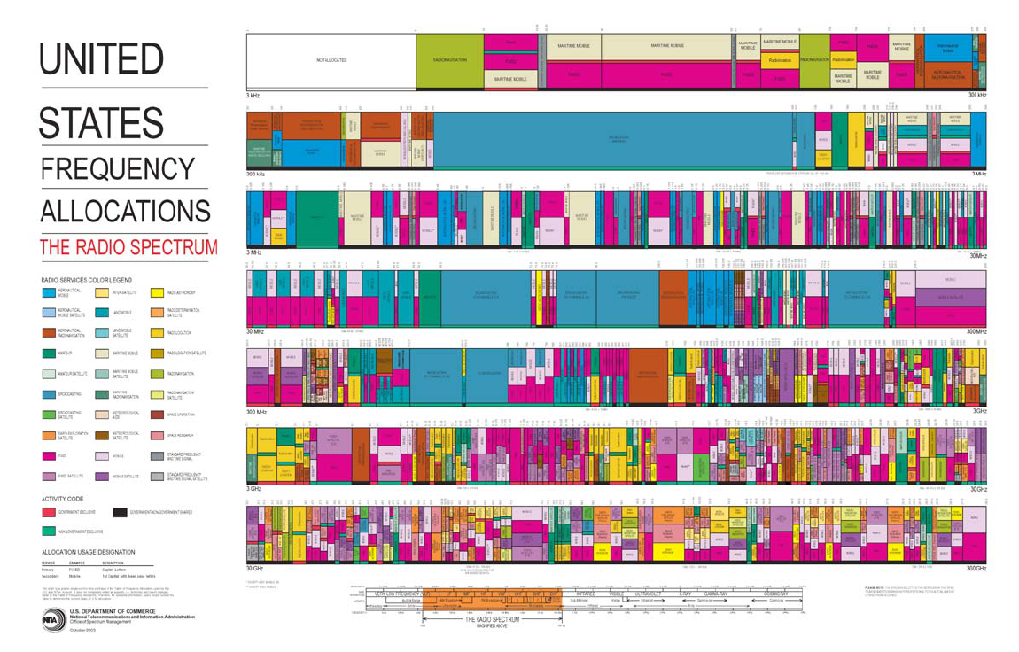
Figure 3-1. Spectrum allocation
3-
3
3-
4

Table 3-1 contains the remaining bands where the government has exclusive primary status.
Many of these bands, however, allow civil use of the spectrum either in a secondary status or
a primary status through a footnote in the regulations. Table 3-2 lists the subset of bands
where there is no other permitted civil use of the frequency. Note that many of the
government’s higher frequency bands are also used for non-government purposes.
Table 3-1. Frequency bands where government has exclusive primary status
14-19.95 kHz 25.33-25.55 MHz 26.48-26.95 MHz 27.54-28.00 MHz
28.89-29.91 MHz 30-30.56 MHz 32-33 MHz 34-35 MHz
36-37 MHz 38.25-39 MHz 40-42 MHz 46.6-47 MHz
49.6-50 MHz 138-144MHz 150.05-150.8 MHz 157.0375-157.1875 MHz
1
162.0125-173.2 MHz
1
173.4-174 MHz 225-328.6 MHz 335.4-399.9 MHz
410.0-450.0 MHz
1
902-928 MHz
2
1.215-1.3 GHz 1.35-1.39 GHz
1.429-1.435 GHz 1.755-1.850 GHz 2.200-2.290 GHz 2.7-2.9 GHz
3.1-3.65 GHz 4.4-4.5 GHz 4.8-4.94 GHz 5.25-5.35 GHz
5.65-5.925 GHz
2
7.125-8.45 GHz 8.4-8.45 GHz 8.5-9.0 GHz
9.5-10.45 GHz 14.4-15.35 GHz 15.7-17.2 GHz 33.4-36 GHz
43.5-45.5 GHz
1. Exceptions in these bands allocate primary use to some non-government users.
2.
These bands are also allotted for industrial, scientific, and medical (ISM) use.
Table 3-2. Frequency bands where the government is the exclusive user
14-19.95 kHz 2.0-2.065 MHz 25.33-25.55 MHz 26.48-26.95 MHz
27.54-28.00 MHz 28.89-28.91 MHz 30-30.56 MHz 32-33 MHz
34-35 MHz 36-37 MHz 38.25-39 MHz 40-42 MHz
46.6-47 MHz 49.6-50 MHz 138-144 MHz 150.05-150.8 MHz
157.0375-157.1875 MHz 162.0375-157.1875 MHz 163.2625–166.2375 MHz 166.2625-169.4125 MHz
169.5375-170.1375 MHz 170.1625-170.2125 MHz 170.3375-170.4125 MHz 170.4375-170-4625 MHz
170.4875-150.5625 MHz 170.5875-171.0125 MHz 171.1375-171.4125 MHz 171.4375-171.4625 MHz
171.4875-171.5625 MHz 171.5875-171.8125 MHz 171.9375-172.2125 MHz 172.2375-172.2625 MHz
172.2875-172.3625 MHz 172.3875-173.0625 MHz 173.0875-173.2000 MHz 173.4-174 MHz
225-328.6 MHz 335.4-399.9 MHz 410.0-412.6125 MHz 412.6375-412.6625 MHz
412.6875-412.7125 MHz 412.7375-412.7625 MHz 412-7875-420.0000 MHz 1.755-1.850 GHz
2.200-2.285 GHz 4.4-4.5 GHz 7.250-8.025 GHz 8.4-8.45 GHz
14.5-14.7145 GHz 43.5-45.5 GHz
This spectrum does not satisfy the full requirements of the Department of Defense
(DoD), so it uses many other bands either in a shared or secondary status. Appendix A
shows a full listing of DoD spectrum usage. Note that much of this spectrum is used on a
non-interference basis (NIB). Since there are separate allocations for government and non-
3-
5
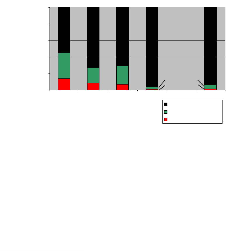
government uses, the DoD is automatically in a secondary status when it tries to use
spectrum in the non-government bands. This has relevance when the DoD wants to use
commercial equipment designed for non-government bands.
1.42
0.74
6.66
8.49
13.73
4.852.81
22.8218.58
30.64
93.71
96.44
70.5
72.92
55.62
0%
20%
40%
60%
80%
100%
0-3.1 3.1-5.925 5.925 - 30 30 - 300 0 - 300
SHARED
NON-GOVT EXCLUSIVE
GOVT EXCLUSIVE
SPECTRUM ALLOCATION
FREQUENCY BANDS (GHz)
Figure 3-2. Allocation of spectrum to federal government and non-federal government
use as a percentage of bandwidth
7
Figures 3-2 through 3-4 illustrate three views of government use of spectrum. Figure 3-2
illustrates the portion of each band as a percentage of total bandwidth that is allocated to
federal government and non-federal government use. The government has the smallest
portion. Figure 3-3 illustrates the portion of the total number of assignments and licenses
that are found in each band. Clearly, the 0-3.1 GHz band is the most used spectrum. This
disproportionate use of the first 3.1 GHz of the 300 GHz of RF spectrum is an indication that
this 1% of the total RF spectrum is the most useful and the most coveted. Figure 3-4
illustrates how government assignments are distributed by government function. Although
national defense has the largest percentage of assignments, it still has fewer than half the
government assignments. This data was compiled using older databases and does not reflect
some of the more recent reallocations of spectrum. These reallocations decrease the
7
These charts were created using data compiled from the NTIA’s Frequency Management Record System
(FMRS) Allocation Table as of 01/29/97, the Government Master File (GMF) as of 07/25/2000, and the
FCC database (DB) as of 1993. This data does not reflect recent reductions in the Government allocations.
3-
6
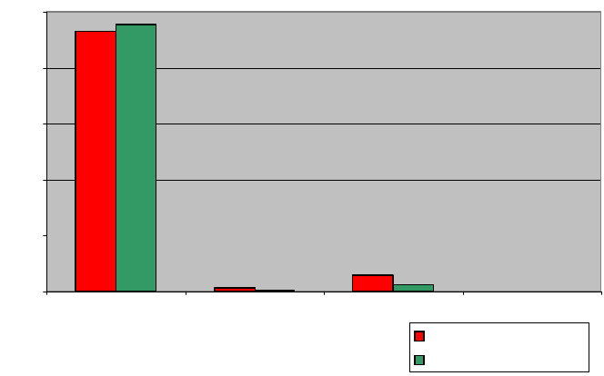
allocations for federal government exclusive use and the portion of the government exclusive
use spectrum used for national defense.
0%
20%
40%
60%
80%
100%
0-3.1 3.1-5.925 5.925 - 30 30 - 300
GOVT ASSIGNMENTS
NON-GOVT LICENSES
FREQUENCY BANDS (GHz)
LOCATION OF ASSIGNMENTS AND LICENSES
93.02
95.57
1.17
0.43
5.71
2.66
0.10 0.12
Figure 3-3. Percentage of total number of assignments and licenses found in each band
6
3-
7
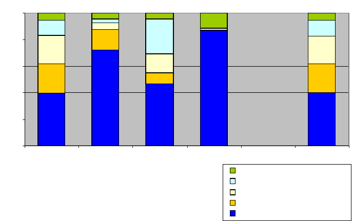
39.46%
72.41%
46.61%
87.31%
40.30%
0%
20%
40%
60%
80%
100%
0-3.1 3.1-5.925 5.925 - 30 30 - 300 0 - 300
Other Services
Transportation
Resources Mgt Control
Law Enforcement & Security
National Defense
FREQUENCY BANDS (GHz)
DISTRIBUTION OF ASSIGNMENTS TO
GOVERNMENT FUNCTIONS
260554* 3280*
16006* 268*
280108*
* Total number of assignments in the band
Figure 3-4. Percentage of total number of assignments to each federal government
function by band
6
3.4 Determining Allocations
The most current information concerning international allocations can be found in the
Radio Regulations (RR) that ITU-R Sector produces after each World Radiocommunication
Conference (WRC). The most current information concerning national allocations can be
found in the NTIA Manual of Regulations and Procedures for Federal Radio Frequency
Management, which is more commonly referred to as the Red Book. Figure 3-5 illustrates
the allocations as they are specified in the two documents. The RR identifies allocations by
region. These regions are shown in Figure 5-2. The U.S. is in Region 2. Both these
documents use the convention that primary service allocations are written in upper case and
secondary service allocations are written in lower case. Footnotes provide exceptions to
these allocations. The Red Book provides the same information on the allocation by region
found in the RR and also shows the allocations for federal government and non-federal
government use. Figure 3-5 shows that the band 162.0125-173.2 MHz is allocated to mobile
and fixed services on a primary basis for federal government use. No secondary services are
identified and no services are identified for non-federal government users. Thus, it shows
that the government has exclusive primary use of this band. However, footnotes can provide
exceptions and we see in the footnote US8 that certain non-federal government users may
use certain parts of this spectrum. The 173.2-174 MHz band allocation shows fixed service
3-
8
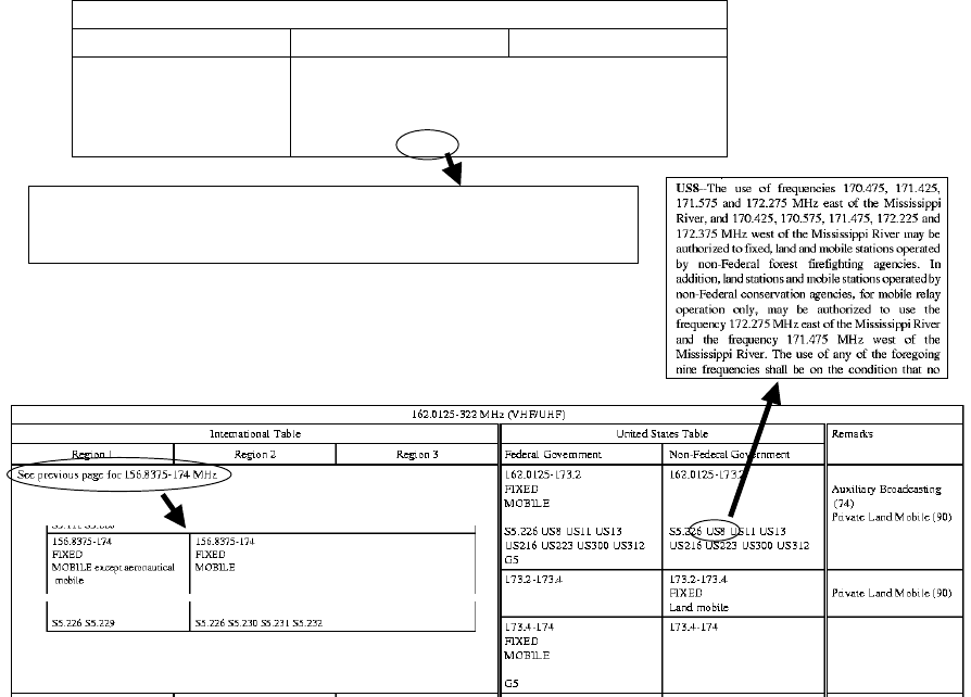
has the primary status and land mobile service has secondary status. Both services are
exclusively for non-federal government use and there are no footnotes with exceptions. If
primary services were shown for both the federal government and the non-federal
government then the band would be considered shared.
Allocation to services
Region 1 Region 2 Region 3
156.8375-174
FIXED
MOBILE except aeronautical
mobile
156.8375-174
FIXED
MOBILE
5.226 5.229 5.226 5.230 5.231 5.232
5.231 Additional allocation: in Afghanistan, China and Pakistan, the band 167-174 MHz is also
allocated to the broadcasting service on a primary basis. The introduction of the broadcasting service into
this band shall be subject to agreement with the neighbouring countries in Region 3 whose services are
likely to be affected.
ITU-R Radio Regulations Table of Allocations
NTIA Red Book Table of Allocations
Figure 3-5. Example frequency allocation entries in the ITU-R Radio Regulations and
the NTIA Red Book
3-
9
3-
10
Section 4
Department of Defense Use of Spectrum and Threats to
that Use
The DoD is the largest government user of spectrum. It uses the radio spectrum from
ELF band through close to 100 GHz in the Extremely High Frequency (EHF) band.
Appendix A provides a detailed listing of current DoD use of various bands from Very High
Frequency (VHF) to EHF. As was pointed out in Section 1, different parts of the spectrum
are better suited for different purposes. In this section, we demonstrate that the DoD’s use of
spectrum is often based on these differences. The variety of missions and environments in
which the DoD uses spectrum requires this breadth of usage. We have also included brief
descriptions of activities that threaten to deny spectrum from DoD users. We attempt to
convey that losses in spectrum availability not only mean less spectrum overall, but also loss
of capability to provide certain services. These developments are made all the more critical
because DoD’s vision for future warfare hinges on the exploitation of communications and
sensor technologies that use the electromagnetic spectrum.
4.1 DoD Capabilities Derived from Use of Spectrum
Many capabilities that are essential to military operations are derived from the use of
spectrum. We attempt to broadly enumerate these capabilities below.
Strategic and Operational Communications: The DoD maintains a robust network of
terrestrial and satellite communications, spanning the spectrum from ELF to EHF, that
supports survivable command and control, worldwide, of U.S. military forces. DoD also
uses commercial satellite services to support many of these functions.
Tactical Communications: The military uses radio communications for tactical command
and control, dissemination of information for targeting, dissemination of information for
warning, and dissemination of information for situational awareness. These services are
achieved through the integrated use of multiple radio systems.
Control Functions: Radio links are used to control the functions of space systems and
unmanned air vehicles (UAVs).
Surveillance Data: Wide band data links are needed to transmit surveillance data obtained
by satellites, UAVs, and manned aircraft to analysis centers in real time. Use of such data has
been crucial for recent military operations.
Infrastructure Support: The military uses radio for various forms of infrastructure support.
These include Land Mobile Radio (LMR) that support various housekeeping and
4-1
administrative functions, air traffic control communications, and point-to-point links that are
used where it is not feasible to use wireline or cable links.
Radio Location: The military has many operational uses for radar systems. These include
long range early warning, surveillance, tracking of targets and other objects both to support
situation assessment and to support weapons system operations, target acquisition for
weapons systems, and precision mapping. Military forces use terrestrial beacon systems and
the GPS to locate forces and also use GPS and terrain following radars to support precision
targeting. Specialized radio beacon systems are used to identify friendly targets as friendly.
This function is needed to avoid fratricide.
Radio Navigation: The military uses multiple radio navigation systems to support
aeronautical and maritime operations. Some of these are operated by DoD, while others are
operated by other agencies. These include on-board radio altimeters. GPS is also used to
support navigation.
Test Support: Various general and specialized radio capabilities are needed to support the
testing of military systems. These include telemetry systems that download test data from
the systems under test to ground-based analysis facilities, weapons scoring systems, systems
that control unmanned targets, systems to terminate the flight of systems under test if they
threaten public safety, and radio location systems that track the positions of test participants.
Training Support: Specialized radio systems are used to support training operations. These
include air combat training systems and a field instrumentation system that add realism to
training operations and support performance assessments.
Troop Morale: The military operates a Family Radio Service and television broadcast
stations to maintain morale.
The DoD’s vision for future warfare hinges on the ability to sense the situation and to
move information. These capabilities are contingent on the availability of spectrum. Just as
the commercial demand for spectrum is increasing, so too is the military’s. Loss of spectrum
not only means a reduced capability when it happens, but it may also mean that a future
capability may not be exploitable.
4.2 Some Salient Factors
The basic factors that affect radio services are frequency, its wavelength, and available
bandwidth. A description of these tradeoffs was presented in Section 1. Here, we list
considerations that are important to DoD uses of the spectrum.
• At low frequency (LF) and below electric charges in the upper atmosphere reflect radio
waves to form an earth-ionosphere waveguide (see Section 1.7.3).
4-2
• Radio waves penetrate seawater at ELF and to some extent at VLF. These frequencies
are required for submarine communications
• At High Frequency (HF), radio waves are refracted off the electrically charged
ionosphere, thus allowing them to propagate long ranges. Prior to communications
satellites, HF (also known as short wave) was the only means of providing long-distance
communications.
• Propagation is limited to line-of-sight for frequencies above HF.
• Atmospheric absorption increases with frequency and ultimately prevents even line of-
sight propagation beyond short distance. Figure 1-22 illustrates atmospheric absorption’s
dependence on frequency.
• Rain attenuates signals even more, especially at SHF and EHF.
• Foliage attenuation is extreme for frequencies starting at UHF and is more severe as
frequency increases. Long range communications at these frequencies require using
higher altitude antennas. For terrestrial communications it requires mounting antennas
on tall masts that can extend above foliage for line-of-sight communications. These
antennas tend to be immobile and may compromise the location of users.
• Hardware, historically, has been developed for lower frequencies first, and later
developed for higher frequencies. Priority of communications service, rather than best
use of spectrum, has been the driving factor in frequency assignments. Some services
occupy lower frequencies since they were the first frequencies available for the service,
not because they were the preferred frequency for the service.
• Wavelength affects the ability of a signal to propagate around or through an obstacle. If
the dimensions of the obstruction are much smaller than a signal’s wavelength, then that
signal can more easily propagate around or through the obstruction.
• When wavelength and obstruction dimensions are comparable, then the wave partially
propagates around the obstruction.
• The wavelength of the radar signals must be much smaller than the dimensions of targets
in order for the target details to be detected.
• The ability of radar to resolve details is also proportional to the bandwidth of the radar
signal.
• Antenna sizes are proportional to the wavelength of signals. As frequencies decrease,
larger antennas are required. It is impractical to put large lower frequency antennas on
mobile platforms.
4-3
• The amount of information that can be transmitted by a communications link is
proportional to the bandwidth that is available to that link. Therefore, with conventional
designs, systems that convey large amounts of information need to operate at higher
frequencies.
• Many operational military systems spread signals over bandwidths that are much wider
than is needed to convey information in order to decrease vulnerability to enemy
jamming or to detection and intercept (see Section 7.4.3). This need for protection
against enemy operations leads to a requirement for much more bandwidth than would be
required to just transmit the same amount of information.
• Achieving efficiency by minimizing the bandwidth used for a service has a
corresponding decrease in reliability, as these signals are more easily detected,
intercepted, and disrupted. They are also more susceptible to noise.
4.3 System Tradeoffs
It is clear from the foregoing considerations that radio system designers need to consider
and trade-off among a large number of factors. Also, it is clear from Appendix A, that the
DoD makes use of a large, varied set of radio services. DoD uses bands throughout the radio
spectrum, as well as spectrum in the lower VHF and the EHF bands which are not
specifically allocated. Communications systems that operate at the lowest frequencies are
used for reliable communications with ships and submarines at sea. However, since the
available bandwidth is low, those systems provide only low data rate messaging. The next
higher frequency bands support both voice and moderate data rate messaging. Appendix A
details DoD spectrum use between 30 MHz to 100 GHz. We see that standard
communications radios generally operate in the VHF and UHF bands, while fixed and
mobile systems that require higher data transfer rates generally operate between 1.3 and 5.0
GHz , with fixed systems operating up to 8.5 GHz. Some terrestrial systems operate at
higher frequencies, but generally, the higher frequencies are used for satellite
communications. The links between satellites and the surface go only a few miles through
the atmosphere, so they are not affected by atmospheric absorption to the same extent as
long-range terrestrial links. Critical command and control facilities and platforms contain a
suite of communications systems that operate in different areas of the spectrum and use
satellite, terrestrial long-range, and terrestrial line-of-sight modes in order to ensure that they
are able to maintain communications with command authorities and with the forces by at
least some means.
Radar designers also need to consider various tradeoffs. Long-range detection radar
systems operate at lower frequencies to take advantage of lower propagation losses. Radars
that resolve details of targets require the use of higher frequencies for two reasons. First, in
order for a signal to resolve details its wavelength must be smaller than the detail it is trying
to resolve. Second, radar antenna directionality is a function of the ratio of the wavelength to
4-4
the antenna size. The smaller wavelengths of higher frequencies enable the use of smaller
antennas to get the desired directionality. The tradeoff for better resolution is shorter radar
range. HF band radar systems provide over-the-horizon detection capability. Long range
land-based radar systems operate in the 1.2-1.4 GHz range. Because of their long
wavelengths, these radar systems cannot resolve details of detected objects or track their
positions precisely. Therefore, such radar systems provide long-range early warning of the
presence of objects. Many target acquisition and tracking radar systems operate in bands in
the 8.5-14 GHz range. The wavelength at 10 GHz is 3 cm, or about one inch, thus radar
systems at this frequency can resolve relatively small details. At this same frequency, an
antenna, about a half meter in size, can resolve direction to a few degrees. These radar
systems usually operate over shorter ranges, due to propagation losses. There are exceptions,
however. Some high-power space surveillance radar systems and experimental missile
defense radar systems operate in these bands. Radar systems that operate in bands between
3-6 GHz provide a mix of long-range and tracking capabilities. In general, tradoffs between
hardware capabilities, antenna sizes, and detection and tracking characteristics make this the
lowest frequency band for airborne and shipborne applications. However, some airborne and
shipborne radar systems do operate in the UHF band. Radar systems that operate in the 15-
35 GHz band are used for short-range precision functions such as terrain-following and
mapping. Experimental research on advance radar techniques is being conducted at higher
frequencies, in the EHF band.
DoD also operates radionavigation systems and uses radionavigation systems that are
operated by other agencies. In particular, DoD provides GPS services using three
frequencies within the 1.1-1.6 GHz band. It operates precision aircraft approach radar
systems in the 9.0-9.2 GHz band, and tactical aircraft landing systems around 15.5 GHz.
These are basically high-resolution, short-range radar systems.
4.4 Spectrum Losses and Restrictions
The current transformation of the armed forces to Network Centric Warfare is dependent
on the availability of additional communications capabilities. Appendix A explicitly
identifies many spectrum bands whose use is expected to increase. Concurrently, the civil
world has discovered the profitability of radio communications. Since these civil services
also need to use large amounts of spectrum, there has been much pressure for the DoD to
share spectrum where feasible and to surrender spectrum for use by those new services where
sharing is not practical. This section reviews various attempts to restrict DoD access to the
radio spectrum and discusses their implications and the measures that have been taken or that
could be taken to ensure that DoD meets its needs for radio spectrum.
4.4.1 Low Power Unlicensed Devices
Under Part 15 of the FCC regulations, low power devices that meet various conditions
are permitted to operate without a license in spectrum bands that are not allocated to critical
4-5

safety services. Many of these devices, including such familiar items as garage door
openers, cordless phones, and baby monitors, operate in bands that are allocated on a primary
basis to military use. Under Part 15, such devices are obliged to accept interference from
users that have proper assignments in that band. Despite this regulatory priority, when users
of such devices have complained about interference from properly assigned military users,
those military users have been directed to modify their operations in order to mitigate such
interference.
This situation may help explain the generally negative reaction to band-sharing
proposals, even when analysis suggests that such sharing would be feasible. If DoD users
are obliged to avoid interference when they have regulatory priority, their position would be
even less secure when the non-government parties that experience interference have equal
status in a band.
4.4.2 General Considerations
In the past decade, many new commercial wireless services have been under
development. These new services require spectrum in order to operate. Most notable among
these are satellite communications and audio broadcast systems, various terrestrial broadband
mobile systems, and ultra wideband (UWB) sensor and communications systems. Based on
their own tradeoffs, most of these systems look for allocations in the 1-4 GHz range, with
some short range systems going up to 6 GHz. However, these bands are already allocated
and heavily used, so allocating spectrum for them to use will necessitate displacing existing
users. Since it is politically more practical to displace government users than to displace
commercial users, government users, specifically DoD, users are especially vulnerable.
Remember, the DoD is the predominant user of government spectrum. In the present and
future, proponents of new technologies are likely to seek to share with or to displace
government users. They will seek to obtain spectrum for their systems through domestic
political and public relations activities. Additionally, many of them may seek allocations
through the ITU. WRC
8
decisions on allocations have binding treaty status. Moreover, once
a service is allocated in some band by an international body, proponents can readily maintain
that it would be to the advantage of the U.S. to follow the rest of the world.
During the 1990’s, it was recognized that spectrum is a valuable resource and that the
government could obtain revenue by auctioning spectrum that was allocated to support
government activities. Under the Omnibus Budget Reconciliation Act of 1993 (OBRA 93),
102 MHz of spectrum was reallocated from exclusive government use to exclusive non-
government use, and another 133 MHz of spectrum was allocated to mixed government/non-
government use. This reallocation, which affected a number of bands between 1390 and
4685 MHz, affected a large number of DoD operations. In 1997, through the Balanced
8
This name has been used since 1995; prior to that the name was World Administrative Radio Conference.
4-6
Budget Act of 1997 (BBA 97), 20 MHz of remaining government spectrum was reallocated.
However, it was soon realized that auctions did not meet revenue estimates and that
government operations had been adversely affected by these reallocations. As a
consequence, the 1999 National Defense Authorization Act (NDAA) required reimbursement
to government users for costs related to 1997 and later reallocations. The 2000 NDAA
returned 8 MHz to government use. It also directed that no DoD systems be displaced from
their bands until the Secretaries of Defense and Commerce and the Chairman of the Joint
Chiefs of Staff certify that alternative frequency band(s) are available to retain the essential
military capability that would be otherwise lost.
4.4.3 Some Specific Cases of Spectrum Loss
Digital Audio Broadcast (DAB): The 1992 World Administrative Radiocommunication
Conference (WARC) allocated the 1452-1492 MHz band generally worldwide for satellite
and terrestrial DAB. This is in the middle of a band that is used in the U.S. for aeronautical
flight test telemetry. U.S. telemetry users objected to any loss of this band. Consequently,
the U.S. originally allocated the 2310-2360 MHz band to satellite DAB. This band had also
been used for aeronautical telemetry. Subsequently, half of that band was allocated to other
non-government services. As a result, U.S. aeronautical telemetry users have lost the use of
50 MHz of much needed spectrum.
The WorldSpace Corporation has proposed to launch a satellite in geosynchronous orbit
to provide DAB service to the Western Hemisphere south of the U.S. border. However, in its
initial design, the radiation from this satellite would have interfered with aeronautical
telemetry at many U.S. test ranges. Initially, WorldSpace attempted to maintain that no
interference would ensue. Subsequently, following substantial efforts by various DoD
organizations to assess this issue, WorldSpace agreed to modify the satellite radiation pattern
to conform to requirements of what was then a draft, and is now an accepted, ITU
recommendation on coordinating aeronautical telemetry and geosynchronous broadcast and
communciations satellites. At this time, there is at least one proposal to launch a
constellation of non-geosynchronous DAB satellites to serve Europe. It is not clear what
standards would be used to coordinate this constellation with aeronautical telemetry, since
there are no existing standards for coordination with non-geosynchronous satellites.
Fixed Wireless Access (FWA): Before 1979, there was a primary allocation to
Radiolocation in parts of the world, including the Western Hemisphere, Eastern Asia, and the
Pacific Basin in the 3400-3700 MHz band. The 1979 WARC removed this allocation and
urged governments to remove radar systems from this band by 1985. Nevertheless, the U.S.
operates major defense radar systems in the 3400-3650 MHz band. These include the
Airborne Warning and Control System (AWACS) radar, key naval radar systems, and a
beacon system that maintains flight formation and locates parachute drop sites. Outside of
the U.S., this band is allocated to the Fixed Service and is used by FWA wireless telephone
systems. Recently, vendors of these systems attempted to introduce FWA systems into this
4-7
band on a shared basis with military radar systems. However, DoD was able to demonstrate
that it was not practical to share this band. The FCC dismissed a proposal for reallocation
without prejudice. This does not mean that this issue will not be raised again at some later
time.
Third Generation (3G) Mobile Telecommunications: The 3G systems are envisioned as
being follow-on systems to cell phones that would support high-speed data transfer in
addition to voice. Such systems could provide streaming video, teleconferencing, and
Internet access to vehicle passengers, pedestrians, and occupants of office buildings who are
away from their desks. WARC 92 recommended that certain bands be set aside for 3G, then
known as International Mobile Telecommunications 2000 (IMT-2000). Many nations have
dedicated those bands to 3G communications, but, in the U.S., those bands had already been
allocated to other non-government services. WRC 2000 recommended that some additional
bands, including the 1710-1885 MHz band, be considered for use by 3G services. However,
it is clear from Appendix A that the 1755-1850 MHz band supports many vital DoD services
and that the DoD also uses the 1710-1755 MHz band at various protected sites. An NTIA
study determined that the DoD needed to continue using these bands and that it was not
feasible for the DoD systems that are already in these bands to share them with 3G systems.
A follow-on study proposed that the 1710-1755 MHz band be paired with another band that
is allocated to various non-government services and that DoD systems be cleared from this
band except at two protected sites. This proposal was accepted in 2002.
Radio Local Area Networks (RLANs): RLANs are unlicensed short-range wireless
networks that provide the same services that are now provided by wired LANs. WRC 2003
allocated bands in the 5-6 GHz range for RLAN services on a global basis. One of these
bands is allocated worldwide for radiolocation and is used by DoD antiaircraft and missile
defense systems and by instrumentation radar systems on test ranges. The U.S. intends to
implement this allocation for use by the Unlicensed National Information Infrastructure (U-
NII), using the appropriate Wireless Fidelity (WiFi) standard. The implications of this U-NII
allocation are uncertain. Individual RLAN installations would probably not ordinarily
interfere with radar systems, but uncontrolled proliferation of such systems could increase
background noise to a level that interferes with radar operations.
Operators of radar systems, worldwide, have been concerned by this potential for
interference. In order to mitigate potential interference to radar systems, WRC 2003 required
that RLAN systems implement dynamic frequency selection (DFS) techniques that would
cause them to avoid transmitting on any channel that is being used by a radar, as well as
implement transmitter power control (TPC) to ensure that RLAN systems emit no more
power than is necessary to maintain connectivity. Since the DoD recently committed itself to
the concept of sharing spectrum wherever it can do so without compromising national
security, it has agreed to this U-NII allocation provided adequate DFS is implemented. An
ITU study group has published draft DFS performance recommendations and the FCC is also
considering DFS performance requirements. However, all parties recognize that further
4-8
studies, based on practical experience, are needed to ensure that DFS can be implemented to
adequately protect radar systems from interference by RLAN systems.
Mobile Satellite Service (MSS): The MSS supports satellite communications by and to
mobile users on earth. For a number of years, some MSS operators have been looking for an
additional international allocation in the 1.5-1.6 GHz range and this has been an agenda item
for recent WRCs. Initially, those operators attempted to obtain an allocation in a band
adjacent to one used by GPS, but various studies demonstrated that MSS would cause
unacceptable interference to the GPS signal. As a result, those MSS operators focused on the
1518-1525 MHz band. We see from Appendix A that, in the U.S., this is part of a band that
is dedicated to use by aeronautical telemetry. Before WRC 2003, this band could be used in
the Western Hemisphere outside of the U.S. by MSS, but there is no such use now.
Recently, WRC 2003 allocated this band worldwide to MSS. There are two potential
problems with this reallocation. The direct problem is that MSS systems that are designed to
serve users outside the Western Hemisphere could interfere with U.S. telemetry, particularly
along the East Coast. The indirect problem is that use of this band outside the Western
Hemisphere could encourage its use within that hemisphere as well. This could lead to the
same type of problem that was encountered with the WorldSpace DAB satellite.
Coordination between telemetry and MSS is subject to the same considerations as is
coordination with DAB satellites. The recommendation that was used to coordinate the
WorldSpace system applies to geosynchronous MSS satellites, but there are no accepted
criteria for coordination with non-geosynchronous MSS satellites.
4.4.4 Ultra Wideband
DoD is in an ambiguous position with regard to impulse Ultra Wideband (UWB). On
one hand, systems that can provide vital military services, such as ground and wall
penetrating radar and communications that are difficult to intercept, operate in this mode. On
the other hand, since such systems spread their signal over those lower frequency bands that
support some of the most basic radio services, the uncontrolled proliferation of unlicensed
UWB systems could create a noise background that could interfere with existing uses. NTIA
studies have demonstrated that GPS is particularly vulnerable to UWB transmissions, and
that other radionavigation systems, as well as satellite earth stations, are also vulnerable.
Therefore, some restriction on UWB devices is needed. The FCC has authorized use of these
devices on a limited basis and the possibility of easing those restrictions is still under study.
The use of UWB signals that are modulated onto carrier frequencies that lie toward the
higher end of the radio spectrum should be much less of a problem, since there are fewer
users at such frequencies and since the atmospheric absorption at extremely high frequencies
limits the effective range of any signal.
4-9
4.4.5 Public Sector Challenges
Although most challenges to DoD use of spectrum come from the private sector, the
Department receives challenges from the public sector as well. For example, state and local
government operators of public safety systems need more spectrum to support their
communications systems. Since it is easier to displace federal government users than it is to
displace private users, there has been pressure to reallocate some government spectrum to
use by public safety systems (see Section 4.6.2).
4.4.6 Government Coexistence Challenges
DoD shares spectrum with other Federal agencies and must therefore coordinate with
those agencies. A prime example of coordination for spectrum access, that is required both
within the U.S. and internationally, is the use of the Joint Tactical Information Distribution
System (JTIDS)/Multifunctional Information Distribution System (MIDS) in the frequency
band (960-1215 MHz) that is allocated to the Aeronautical Radionavigation Service (ARNS).
This frequency band, which in the U.S. is a shared band, is used primarily for civil aviation
and safety air traffic control systems. Coordination between the DoD, NTIA, FCC, and the
Federal Aviation Administration (FAA) or the equivalent agencies in each sovereign nation,
is required. NTIA stipulates the conditions under which the DoD can operate the system in
the United States and its Possessions (US&P). As the JTIDS/MIDS has been determined by
the NTIA to provide mainly non-ARNS services, it is authorized to operate, within the
US&P, in the frequency band via a footnote to the U.S. Table of Frequency Allocations, with
the condition that harmful interference not be caused to the ARNS. Such an operational
status in the band requires that conditions and restrictions be placed in the JTIDS/MIDS
Spectrum Support Certification to preclude interference and that the design of the terminals
be certified by NTIA as operating under compatible conditions.
Over the years, the attainment of a spectrum support certification and the certification of
terminals has been very challenging as the FAA and NTIA have insisted on very strict
standards, and the FAA has had its own plans for new systems in the frequency band. An
Electromagnetic Compatibility (EMC) Test Program was initiated in the 1970s and
completed in 1999. Data has been taken and operations have occurred for over 25 years
without an incident of reported interference. A spectrum support certification with
conditions that would support the required levels of DoD training requirements is scheduled
to be completed in the near future.
In 2002, the Department of Transportation (DoT) (mainly the FAA) and the DoD made
agreements for the long term sharing of the frequency band. DoD would agree to build in a
capability to clear a portion of the band in exchange for the following:
1) DoT/FAA would procure systems above 1030 MHz to be compatible with
JTIDS/MIDS;
2) DoT support for some sort of recognition of JTIDS/MIDS in the frequency band;
4-10
3) DoT support for a JTIDS/MIDS spectrum support certification and a US&P
frequency assignment that would meet DoD training requirements;
4) DoT support for a process whereby DoD would self certify the EMC features of their
JTIDS transceivers (a.k.a. Link-16 terminals).
As part of their agreement, DoD will ensure that by 2020, all Link-16 terminals are
capable of re-mapping frequencies from below 1030 MHz to the sub-band above 1030 MHz.
DoD will use this capability as required within the US&P to prevent harmful interference to
aviation systems implemented below 1030 MHz that are approved by NTIA. This capability
would be used to remap the minimum number of frequencies to promote compatibility as
determined by the NTIA.
4.5 Maintenance of Spectrum Capability
In the face of growing needs, coupled with spectrum losses, what do we need to do to
ensure that sufficient spectrum is available? One approach is to use alternate means, where
feasible. For example, we should consider replacing wireless links between fixed sites with
copper or fiber optic cable, and we should also consider laser communications.
In general, however, such alternatives will not be practical and we will need to consider
what can be done to most effectively use the available radio spectrum. No single approach
will suffice. Section 7 discusses a number of approaches, including new modulation
techniques that better confine signals within their assigned bands, the use of antennas that
direct signals to their intended receivers, and various techniques that opportunistically use
inactive radio channels.
4.6 DoD Use of Spectrum in the United States and its Possessions (US&P)
DoD makes extensive use of spectrum within US&P. Uses include training operations,
facility operations, test and evaluation (T&E), access to home bases, North American Air
Defense, and, in the last year, Homeland Security. Spectrum losses and restrictions, together
with the need for more spectrum to support operations, have lead to a number of difficulties.
The magnitude of these difficulties will only increase unless we are able to improve our
utilization of spectrum.
The following subsections address test and training issues; operation of posts, camps,
stations, and ports; and military operations issues. The final section covers the overarching
issue of negotiating the use of this same spectrum with other nations when its use is near our
nation’s borders.
4.6.1 Test and Training
The U.S. armed forces must train in the same manner that they will actually fight in order
to ensure that they are properly prepared for any contingency. The Joint Forces Command
4-11
estimates that 80 percent of this training takes place within the Continental United States
(CONUS) or within 100 miles of its coastline. Most of the major test ranges are located on
the US&P. However, limits on allocated spectrum and various restrictions on the use of
spectrum impair their ability to conduct realistic training. In addition, comprehensive testing
is needed to ensure that military systems are capable of performing their missions. Testing
requires the support of radars, telemetry, and other data transfer systems. Test capabilities
have been adversely impacted by loss of spectrum, as well as the inability to find more
spectrum for ever increasing data transfer requirements. Some specific cases of past and
potential future spectrum losses that impact test and evaluation were discussed in Section
4.3. Certain issues deserve special note.
Many major test and training ranges are located in the Southwest U.S., near the
Mexican border. Currently, there is no protection from interference from Mexico.
Expected future agreements could result in protection for half the spectrum in bands
that are subject to agreement, and loss of use of the remainder of such bands. Many
major test and training facilities lie within the sharing zone for terrestrial systems.
Airborne systems that operate within line-of-sight of the Mexican side of the sharing
zone would also be affected. This could affect operation of test and training ranges
that lie several hundred miles north of the border.
•
•
•
Use of electronic attack systems that intentionally jam radio frequencies is extremely
restricted within the US&P. Such jamming is used to defeat targeting by enemy
weapons systems and to disrupt enemy communications. Realistic training requires
that the armed forces train with these systems the way they would be used in actual
operations but they cannot do it because of these restrictions. The armed forces also
need to test their systems in a realistic jamming environment in order to evaluate
system performance. Because of these restrictions, for example, the Marines are
forced to conduct training operations using the EA-6B “Prowler,” the primary
airborne electronic attack system, at least 150 miles offshore. This requirement
impairs crew safety, since the aircraft must operate beyond the range of immediate
Search and Rescue capabilities. If a band is exclusively allocated to military use, it is
more feasible to conduct realistic electronic attack operations against systems in this
band. This was one consideration in the FWA proceeding that was discussed in
Section 4.3.
Restricting DoD systems to a limited number of bands has led to increased
interference between different systems that are needed to support a given operation.
For example, the Marine Corps has identified interference between their Pioneer
Unmanned Air Vehicle (UAV) and their AN/TRC-170 Microwave Radio Terminals,
which operate in the same relatively narrow band. Operations require the
simultaneous employment of both systems. This has proved to be a difficult
undertaking. In general, because of limitations in the availability of radio spectrum,
new systems must be designed so that there is no interference between the new
4-12
system and existing systems that operate in the selected band. This strains
technology and increases system cost.
Some ranges deploy key legacy systems that cannot readily be changed. For
example, the Marine Corps has established a need to protect legacy systems operating
in the 1710-1755 MHz at their Yuma and Cherry Point Air Stations. As a
consequence, protection of these sites was maintained in the 3G reallocation that was
discussed in Section 4.4.3.
•
•
•
Range support systems have been particularly vulnerable to reallocation. A
significant amount of spectrum that was previously allocated to range telemetry has
been lost. If the proposed reallocation of the 1755-1850 MHz to 3G had taken place,
then Air Combat Training Systems that support realistic air combat training and the
evaluation of combat performance would have had to find new spectrum. Use of
Flight Termination Systems, which are used to terminate the flight of missiles,
drones, and other unmanned aircraft that deviate from their proper flight path on test
ranges, could have been adversely affected by bilateral agreements with Mexico.
Due to the lack of government-allocated spectrum that was suitable for their
purposes, some training systems were designed to operate in non-government bands
on a non-interference basis. They would, for example, operate on television (TV)
channels that were not assigned for use in the vicinity of their range. However, the
assignment of additional bands to support the introduction of digital TV and the
expansion of other commercial services into remote areas negates this approach.
4.6.2 Posts, Camps, Stations, and Ports
Posts, camps, stations, and ports can be viewed as small cities that use spectrum for daily
operations in addition to their training, testing, and military operations. The additional uses
of spectrum support administration, safety, and security functions. The bands that are
available for these uses are 138-144 MHz, 380-400 MHz, and 406-420 MHz. Additionally,
the Corps of Engineers uses the 162-174 MHz band for their operations nationwide.
Currently, these bands are threatened with encroachment from the bands allotted to state and
local public safety, which include the 150.8-162 MHz and the 450-470 MHz bands. The
proximity of the 138-144 MHz and the 162-174 MHz government bands to the first public
safety band leaves them vulnerable to suggestions for extending the public safety band. The
380-400 MHz and 406-420 MHz bands are similarly threatened. The predominant land
mobile radio that is used for state and local public safety in the 450-470 MHz band is tunable
down to 380 MHz. Thus, the 380-400 MHz and 406-420 MHz bands can be subsumed by
public safety radios with minimum infrastructure costs.
4-13
4.6.3 Military Operations
Several naval ship radars operate in a band that is adjacent to a satellite downlink band.
There have been a number of reports of adjacent band interference with satellite
communications systems and with satellite TV. Generally, interference has been attributed
to poorly designed receivers that do not filter out signals that lie in the radar band. In
general, however, since radars transmit high power and satellite earth stations are very
sensitive, the potential for adjacent band interference exists even for well-designed receivers.
As previously noted in Section 4.4.1, many low power unlicensed devices operate in
military bands. Such devices operating in the vicinity of military bases often experience
interference. In addition, devices that are used in seaports are vulnerable to interference
when naval vessels are in port.
AWACS aircraft radars have been used for surveillance in support of North American
Air Defense and are now also used in support of Homeland Defense. If, as noted in Section
4.4.3, FWA operations had been allocated to share a band with AWACS radar, as proposed,
it would have been difficult to operate AWACS without the potential for interference. Since
the issue of using this band for the FWA may be raised again it is important that those
making decisions on the allocation of spectrum are aware of its significance in Homeland
Defense.
4.6.4 Coordination with Neighboring Countries
Spectrum on border regions must be shared with neighboring countries. Many
restrictions are placed on DoD use of spectrum in these regions. The following discussions
identify the more current issues that pertain to Canada and Mexico.
Canada: There have been recent discussions between the DoD and the Canadian
government on the introduction of FWA systems into Canada. These systems have already
been licensed in rural areas, and the Canadian government proposes to auction spectrum for
use by FWA systems in urban areas in the near future. There is a potential for interference
with AWACS, not only in border areas but also where AWACS is used in Canadian airspace
for North American air defense. There is also a potential for interference between Canadian
FWA in coastal areas and U.S. naval radar systems that operate at sea and in border waters.
As a result of these discussions, the Canadian authorities structured their allocation to
minimize potential interference with AWACS and also worked with DoD to develop
information on potential interference to FWA that could be provided to potential bidders at
the Canadian auction. Previously, the U.S. had worked with Canadian authorities to
coordinate between Canadian terrestrial DAB and U.S. aeronautical telemetry in border
areas. Coordination with Canada is carried out through a bilateral agreement that covers
government and non-government terrestrial radio services above 30 MHz.
4-14
Mexico: The U.S. is in the process of coordinating with Mexico on sharing the use of
various VHF and UHF bands in the border region. There are many DoD test and training
installations in the Southwest in the neighborhood of the Mexican border. As we see in
Appendix A, DoD makes substantial use of these bands for operational and support
communications and for radar systems, so that sharing these bands will have a major impact
on test and training operations. In particular, airborne operations within several hundred
miles of the border could be affected.
4.7 DoD Use of Spectrum Outside the US&P
The DoD uses spectrum worldwide. The allotments and assignments within the US&P
only apply to the US&P. This has three ramifications. First, before the DoD can use
spectrum worldwide, its use must be coordinated with all countries that will be affected.
Second, equipment must be developed to operate on the potential assignments that are or will
be available worldwide. Third, the DoD must ensure that their requirements receive proper
attention at WRCs and before ITU study groups. The following subsections elaborate on the
first two ramifications. The procedures of international regulation and DoD participation in
processes are discussed in Sections 5 and 6.
4.7.1 Host Nation Support
U.S. military forces are stationed in foreign countries around the world. These forces
must operate their radio systems in accordance with the laws, regulations, and allocations of
the host nations. Since no other country maintains a military force on the scale of the U.S.
forces, most countries do not maintain an extensive allocation for military uses, and such
allocations that exist differ between countries. Combatant commanders are responsible for
coordinating the use of spectrum with host nations. It is a misconception that DoD can
disregard these coordination requirements during wartime operations. RF emissions are
rarely confined to the territory of the enemy.
4.7.2 International Spectrum Supportability
U.S. acquisition programs need to allow for host nation spectrum supportability from
their earliest stages. Unfortunately, it is not always feasible to identify what nations will host
a given system and impossible to predict, with the ever increasing requirements for wireless
services, what allocations will be available when a system is finally deployed. The DoD has
invested much effort into developing databases of host nation requirements so potential
conflicts can be identified more easily. Identifying the spectrum in which new systems will
operate is a critical part of their development and acquisition.
To help mitigate the uncertainty of worldwide spectrum availability, newer systems are
being designed to operate over larger bands of spectrum than that sanctioned by US&P
allocations. This increases the potential for supportability in other nations. As an example,
the Joint Tactical Radio System (JTRS) is being designed to operate from 2 MHz to 2 GHz.
4-15
This mitigation technique is not applicable to all systems. As described earlier, some
systems can only achieve the desired performance result in a limited portion of the spectrum.
4.8 Summary
DoD uses the full range of frequencies that are available to provide communications,
radar, and radiolocation services. Since the transformation of the armed forces involves
heavier use of communications and sensor systems, DoD requirements will only increase.
Simultaneously, there is greater demand for commercial availability of spectrum. History
has shown that political entities are more responsive to commercial interest, and that taking
spectrum from defense uses and allocating it to new civilian services is perceived as easier
than reallocating civilian uses of spectrum. Economic benefits to governments through
public auctions make it an even more enticing course of action. History has also caused DoD
users to view spectrum sharing as an undesirable solution as it may, de facto, relegate DoD
users to secondary status even when they have the primary allocation of the band. Civilian
users of commercial equipment that operate in frequency bands where the civilian use has
secondary status are usually unaware of this status and believe by buying the equipment that
they have the right to uninterrupted use. Any interference caused by defense spectrum users
is seen as unwarranted. Civilian complaints to political entities and the latter’s responses
result in restrictions being placed on the DoD users. The DoD has already experienced
numerous losses of spectrum and is continuously struggling to retain the capabilities it needs
to perform its mission.
4-16

Section 5
Spectrum Management Organizations and U.S.
Participation in World Radiocommunication Conferences
In this section we describe the current national and international frequency management
organizations. The objective is to identify the key functions of each organization and how
they contribute to the task of spectrum management.
5.1 International Spectrum Management
The ITU is the United Nations’ agency for matters dealing with the telecommunications
field. Within the ITU, the ITU-R carries out activities concerning all matters dealing with
radio communications and spectrum management. WRCs allocate the international RF
spectrum. The Radiocommunication Bureau (BR) registers frequency assignments and
maintains the master international frequency register. The BR also publishes advance
information and coordination information about upcoming systems and assists in resolving
interference. Periodically, the ITU publishes the RR, which is the recognized framework for
the use of the spectrum. These regulations have treaty status. The frequency management
administrations of ITU member nations generally develop national frequency allocation
policies consistent with the RR. The ITU publishes the RR as agreed at the WRCs. States
are still sovereign and may operate systems pursuant to Section 4.4 of the RR, provided they
do not cause and are willing to accept interference.
Figure 5-1 shows the organization of the ITU. Four of the ITU-R organizations affect
frequency management: the WRC, the Radio Regulations Board (RRB), the BR, and the
Radiocommunication Study Groups (SGs).
WRC meetings occur periodically, currently, ever four years.
9
Each WRC has a specific
agenda associated with specific radiocommunication services. Each WRC updates the RR,
which contain the allocations of the RF spectrum to the various radio services. These
allocations have worldwide effect except where regional or national requirements differ and
regional members agree to these differences. Figure 5-2 illustrates the three recognized
regions of the world. Tropical areas, the region centered on the equator and shaded in Figure
5-2, have additional provisions to offset their higher electrical noise. Exceptions to
allocations for specific countries appear as footnotes in the allocation tables of the RR.
Section 3.4 provides an example of how allocations are specified in the RR.
9
A shorter period of two years was tried but it was abandoned since it did not provide adequate time for the
issues to be studied appropriately.
5-1

Plenipotentiary Conference
Supreme organ of the union, establishes overall policy and budget; meets every two years
The International Telecommunication Union
World
Conferences on
International
Telecommuni-
cations
ITU Council
Acts on behalf of the
Plenipotentiary Conference
meets once a year
World
Telecommunication
Advisory Council
Secretary General
Deputy Secretary
General
General Secretariat
Coordination
Committee
Radiocommunication
Sector (ITU-R)
Telecommunication
Standardization Sector (ITU-T)
Telecommunication
Development Sector (ITU-D)
Ensures the rational, equitable,
efficient, and economical use of
radio-frequency spectrum by all radio
services, including those using the
geostationary-satellite orbit
Studies technical, operating, and
tariff questions and adopts
recommendations with a view to
global telecommunications
standardization
Facilitates and enhances
telecommunications development
worldwide
World/Regional
Radiocommunication
Conferences
Radiocommunication Assemblies
Radio
Regulations
Board
Study Groups
Director BR
Radiocommunication
Bureau (BR)
Advisory Group
World Telecommunication
Standardization Conferences
Study Groups
Director TSB
Telecommunication
Standardization
Bureau (TSB)
Advisory Group
World / Regional
Develoment Conferences
Study Groups
Director BDT
Telecommunication
Development
Bureau (BDT)
Advisory Group
Figure 5-1. Organization of the ITU
5-2
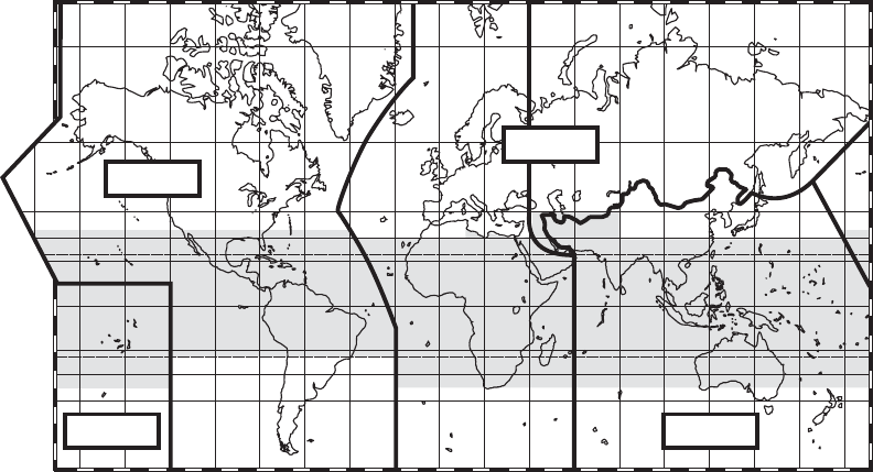
7 5
°
6 0
°
4 0
°
3 0
°
2 0
°
0
°
2 0
°
3 0
°
4 0
°
6 0
°
7 5 °
6 0 °
4
0 °
3 0 °
2 0 °
0 °
2 0 °
3 0 °
4 0 °
6 0 °
1 7 0 °
1 4 0 °1 6 0 ° 1 0 0 °1 2 0 ° 6 0 °
8 0 °
2 0 °4 0 ° 0 ° 2 0 ° 4 0 ° 6 0 °
8 0 °
1 0 0 ° 1 2 0 ° 1 4 0 ° 1 6 0 ° 1 8 0 °
1 7 0 °
1 7 0
°
1 4 0 °1 6 0 ° 1 0 0 °1 2 0 ° 6 0 °
8 0 °
2 0 °4 0 ° 0 ° 2 0 ° 4 0 ° 6 0 °
8 0 °
1 0 0 ° 1 2 0 ° 1 4 0 ° 1 6 0 ° 1 8 0 °
1 7 0
°
ABC
ABC
R E G I O N 1
R E G I O N 2
R E G I O N 3
R E G I O N 3
Figure 5-2. Spectrum use regions
The RRB approves the Rules of Procedure used by the BR to register frequency
assignments. It addresses matters referred by the BR that cannot be solved by RR or the
rules. It adjudicates interference conflicts among member nations.
The BR operates under the Rules of Procedure established by the RRB to achieve an
orderly recording and registration of frequency assignments, and, when necessary, the
associated orbital characteristics of satellites. It maintains the Master International
Frequency Register. It also advises member nations and the RRB on technical matters of
interference and spectrum use.
The SGs study a variety of questions relating to radiocommunication issues. The focus
of their work is on the use of RF spectrum in terrestrial and space communications, the
characteristics and performance of radio systems, the operation of radio stations, and the
radiocommunication aspects of distress and safety matters. Currently there are 7 study
groups:
SG 1 - Spectrum management
SG 3 - Radiowave propagation
SG 4 - Fixed-satellite service
SG 6 - Broadcasting services (terrestrial and satellite)
5-3
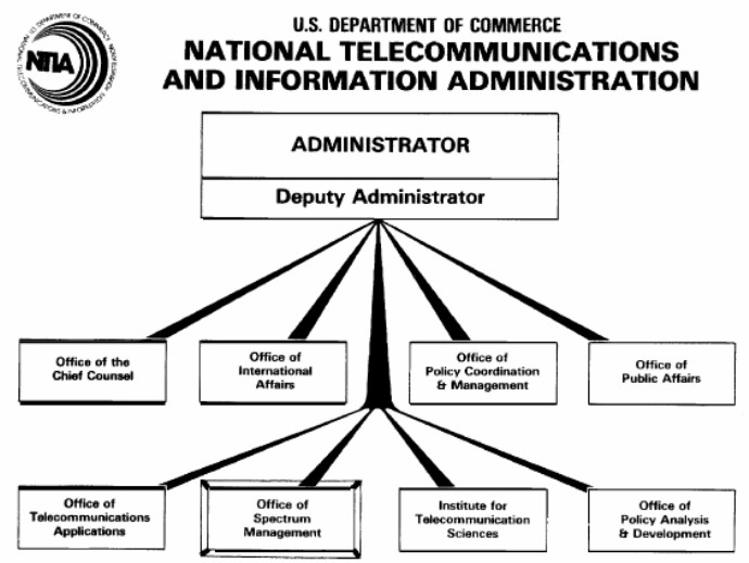
SG 7 - Science services
SG 8 - Mobile, radiodetermination, amateur and related satellite services
SG 9 - Fixed Service
5.2 National Spectrum Management
The Communications Act of 1934 established a duality in spectrum management in the
U.S. between the President for federal government stations and the FCC under the direction
of Congress. By executive order, the President delegated his functions under the act to the
NTIA which is placed under the Secretary of Commerce.
5.2.1 The National Telecommunications and Information Administration (NTIA)
Figure 5-3 illustrates the organization of NTIA. NTIA performs its spectrum
management function through the Office of Spectrum Management (OSM) governed by the
NTIA Manual of Regulations and Procedures for Federal Radio Frequency Management.
Figure 5-4 illustrates the organization of the OSM. Two committees advise the OSM: the
IRAC and the Spectrum Planning and Policy Advisory Committee (SPAC).
Figure 5-3. Organization of the NTIA
5-4
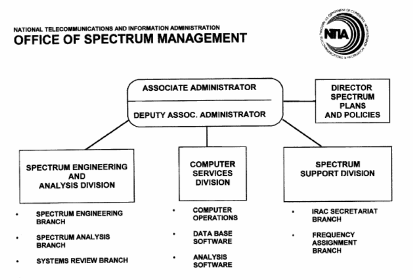
Figure 5-4. Organization of the NTIA Office of Spectrum Management
The mission of the IRAC is to assist the Assistant Secretary in the discharge of his
responsibilities pertaining to the use of the electromagnetic spectrum. The basic function of
the IRAC is to assist in assigning frequencies to U.S. government radio stations and to
develop and execute policies, programs, procedures, and technical criteria pertaining to the
allocation, management, and use of spectrum. The IRAC consist of representatives
appointed by each of the following member departments and agencies:
Agriculture
Air Force
Army
Broadcasting Board of Governors
Coast Guard
Commerce
Department of Energy
Federal Aviation Administration
Federal Emergency Management Agency
General Services Administration
Health and Human Services
5-5

Interior
Justice
National Aeronautics and Space Administration
National Science Foundation
Navy
State
Treasury
U.S. Postal Service
Department of Veterans Affairs
Several DoD agencies provide observers to the IRAC: i.e., The Office of the Assistant
Secretary of Defense, NII, and the Defense Information Systems Agency (DISA).
Additionally, the FCC provides a liaison to the IRAC.
The IRAC consists of six subcommittees. Their missions and roles follow:
Emergency Planning Subcommittee (EPS): Formulates, guides and reviews National
Security Emergency Preparedness (NSEP) planning for spectrum-dependent systems.
Frequency Assignment Subcommittee (FAS): Carries out those functions related to the
assignment and coordination of radio frequencies and the development and execution of
procedures for this purpose. The FAS is divided into two groups: the Aeronautical
Assignment Group (AAG) and the Military Assignment Group (MAG). As their names
imply, the AAG makes recommendations concerning aeronautical use of the spectrum and
the MAG makes recommendations on military uses. Specifically, the AAG reviews all
assignment of frequencies in the bands listed in Table 5-1 and the MAG reviews assignments
in the 225.0-328.6 MHz and 335.4-399.9 MHz bands:
Table 5-1. AAG frequency assignment bands
190-285 kHz 285-435 kHz 510-535 kHz 74.8-75.2 MHz
108-121.9375 MHz 123.5875-128.8125 MHz 132.0125-136 MHz 328.6-335.4 MHz
978-1020 MHz 1030 MHz 1031-1087 MHz 1090 MHz
1104-1146 MHz 1157-1213 MHz 5000-5250 MHz
Space System Subcommittee (SSS): Is responsible for international registration of
government satellite systems within the ITU forum. It gets involved in all NTIA business
concerning space systems.
Spectrum Planning Subcommittee (SPS): Is responsible to the IRAC for all matters
pertaining to planning the use of electromagnetic spectrum.
5-6
Technical Subcommittee (TSC): Is responsible to the IRAC for functions that relate to the
technical aspects of the use of electromagnetic spectrum. The TSC evaluates and makes
recommendations concerning new or existing radiocommunication techniques that affect the
use of electromagnetic spectrum.
Radio Conference Subcommittee (RCS): Undertakes the preparatory work related to
international radio conferences and matters concerning negotiations with international
organizations.
The Spectrum Planning and Policy Advisory Committee (SPAC) consists of 15 non-
Federal members and 4 Federal members, all appointed by the Secretary of Commerce. The
non-federal members are appointed to provide a balanced representation of relevant matters
such as manufacturing, analysis and planning, commercial and other operational spectrum
use, research, academia, and international negotiations. Their role is to review the
recommendations of the IRAC, review the progress of electromagnetic compatibility
programs, provide recommendations on U.S. proposals on spectrum matters with respect to
ITU conferences, and provide strategic planning and recommendations on the efficient use of
spectrum.
5.2.2 The Federal Communications Commision (FCC)
The FCC regulates non-federal government telecommunications and is directly
responsible to Congress. The Rules and Regulations that the FCC follows are codified in
Title 47 of the Code of Federal Regulations. The FCC maintains a liaison with all IRAC
meetings and subcommittees but is not an IRAC member. This liaison assists in spectrum
management actions requiring FCC coordination.
Figure 5-5 illustrates the current organization of the FCC. The roles and responsibilities
of the different bureaus and the Office of Engineering and Technology (OET) follow. Note
that the OET is the arm of the FCC responsible for spectrum management. These
descriptions are taken from the FCC internet site, http://www.fcc.gov/aboutus.html.
The FCC is directed by five Commissioners appointed by the President and confirmed by
the Senate for 5-year terms, except when filling an unexpired term. The President designates
one of the Commissioners to serve as Chairperson. Only three Commissioners may be
members of the same political party. None of them may have a financial interest in any
Commission-related business.
As the chief executive officer of the Commission, the Chairman delegates management
and administrative responsibility to the Managing Director. The Commissioners supervise all
FCC activities, delegating responsibilities to staff units and Bureaus.
5-7
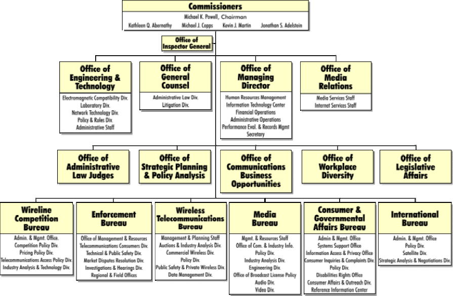
Figure 5-5. FCC organization chart
The Commission staff is organized by function. There are six operating Bureaus and ten
Staff Offices. The Bureaus’ responsibilities include: processing applications for licenses and
other filings; analyzing complaints; conducting investigations; developing and implementing
regulatory programs; and taking part in hearings. The Offices provide support services. Even
though the Bureaus and Offices have their individual functions, they regularly join forces and
share expertise in addressing Commission issues.
Consumer & Governmental Affairs Bureau: Communicates information to the public
regarding Commission policies, programs, and activities. This Bureau is also charged with
overseeing disability mandates.
Enforcement Bureau: Enforces the Communications Act, as well as the Commission’s
rules, orders, and authorizations.
International Bureau - represents the Commission in satellite and international matters.
Media Bureau: Regulates AM, FM radio and television broadcast stations, as well as
Multipoint Distribution (i.e., cable and satellite) and Instructional Television Fixed Services.
5-8
Wireless Telecommunications: Oversees cellular and PCS phones, pagers and two-way
radios. This Bureau also regulates the use of radio spectrum to fulfill the communications
needs of businesses, local and state governments, public safety service providers, aircraft and
ship operators, and individuals.
Wireline Competition Bureau: Responsible for rules and policies concerning telephone
companies that provide interstate, and under certain circumstances intrastate,
telecommunications services to the public through the use of wire-based transmission
facilities (i.e., corded/cordless telephones).
Office of Engineering And Technology: Allocates spectrum for non-government use and
provides expert advice on technical issues before the Commission.
5.3 International Negotiation
Bilateral and multilateral negotiations and agreements concerning telecommunications
and spectrum use are functions of the Department of State (DoS). The DoS leads the
American participation in all international radio spectrum negotiations. The delegations that
participate in these negotiations are ad hoc. Preparations for these meetings involve inputs
from multiple government organizations and private interests.
5.3.1 The Department of State Organization that Handles International
Communications Issues
The DoS Bureau of Economic and Business Affairs (EB) has responsibility for
international negotiations concerning telecommunications issues. This bureau is managed by
the DoS International Communications and Information Policy (CIP) organization. CIP is
organized into three offices: the Office of Bilateral Affairs (CIP/BA), the Office of
Multilateral Affairs (CIP/MA), and the Office of Strategic Planning and Satellite Policy
(CIP/SP), These offices are led by the Coordinator for International Communications and
Information Policy. All three offices could potentially get involved in spectrum issues, e.g.,
the CIP/BA in spectrum issues affecting neighboring countries, or the CIP/MA in its
participation in international conferences, specifically,
The Asia-Pacific Economic Cooperation (APEC),
The Commission for Inter-American Telecommunications (CITEL),
The Organization for Economic Cooperation and Development (OECD),
The ITU, and
The CIP/SP in all matters concerning satellites.
The CIP is supported by two advisory committees, the Advisory Committee for
International Communications and Information Policy (ACICIP) and the International
5-9
Telecommunications Advisory Committee (ITAC). It is the ITAC that develops U.S.
positions for meetings of international treaty organizations.
The ITAC is divided into sectors and study groups that match those of the ITU. There
are three sectors: Telecommunications Standardization (ITAC-T), Telecommunications
Development (ITAC-D), and Radiocommunications (ITAC-R). These in turn are divided
into the following study groups:
ITAC-T includes three study groups:
Study Group A: U.S. policy, standardization, regulation, and competitive aspects of the
operations and tariffs of telecommunications services.
Study Group B: Switching and signaling for transmission systems, integrated services
digital network (ISDN), and software languages.
Study Group D: Data networks and telematic transmission service, digital video, modem,
and digital circuit multiplication techniques
ITAC-D includes two study groups:
Study Group 1 - Telecommunication development, strategies, and policies
Study Group 2 - Development, harmonization, management and maintenance of
telecommunication networks, and services including spectrum management
ITAC-R includes seven study groups:
Study Group 1: Spectrum management
Study Group 3: Radio wave propagation
Study Group 4: Fixed satellite service
Study Group 6: Broadcast Service
Study Group 7: Science services
Study Group 8: Mobile, radiodetermination, amateur, and related satellite services
Study Group 9: Fixed service
In addition to coordinating frequency use through the ITU, the U.S. also coordinates with
nations on its border. For example, there are separate agreements with Canada and Mexico.
5.3.2 Procedures for WRC Participation
At the conclusion of each WRC, a series of domestic and international meetings are held
in preparation for the next WRC. In the first, the Conference Preparatory Meeting (CPM),
delegates review the agenda items that were adopted by the previous WRC and attempt to
5-10
identify areas requiring study before decisions can be made at the next WRC. Also, as part
of this first CPM, as best possible, the outline of the technical report that the second CPM
will forward to the WRC is developed. These products form the basis of each member
country’s preparation for the next conference.
The DoS then takes several actions.
National participation in the WRC begins with participation in the first CPM. At the
conclusion of the CPM, the study areas that are identified for the next WRC are assigned to
the appropriate ITAC-R study group. Activities under ITAC-R prepare for the international
meetings that will build the technical and operating bases (called the CPM report) for the
next WRC. The ITAC-R and its study groups review the CPM outline, create any additional
joint domestic groups needed to do the preparatory work and develop contributions for the
international meetings that develop the CPM inputs. The preparatory process can involve
about a two to four year effort by private sector interests and government agencies. During
the preparatory process, DoS coordinates the activities of the various study groups, clears
U.S. papers through the ITAC-R national committee for submission to dozens of
international meetings, and accredits and leads U.S. delegations as appropriate.
Shortly after DoS activities get underway the NTIA and FCC begin their respective
preparatory activities. NTIA activates its Radio Conference Subcommittee. During the
NTIA activities, all government agencies review their requirements for international
spectrum support taking account of the existing and planned systems the agencies operate.
Agencies negotiate among themselves any conflicting proposals for spectrum. FCC staff
participate as liaison members to the Radio Conference Subcommittee. The end product is
the recommended government proposals that NTIA forwards to the DoS.
The FCC creates an advisory committee of private sector interests that develops non-
government proposals. Any non-government entity can participate in the FCC advisory
committee. The advisory committee members negotiate among themselves to develop a
report of recommended conference proposals to the FCC. Government agencies may
participate, as appropriate, in meetings of the advisory committee. FCC staff use the
advisory committee report to develop non-government proposals.
There is very close coordination between NTIA and FCC as their respective activities
mature into preliminary views and U.S. draft proposals. On controversial issues, domestic
negotiations between FCC, NTIA, and interested government agencies result in identical
proposals being forwarded to the DoS by FCC and NTIA. There is also close coordination
among FCC, NTIA, and the DoS as the ITAC-R activities unfold to ensure that the technical
preparations are consistent with the evolving proposals being developed. As draft proposals
evolve, they are presented at bilateral, regional, and multilateral meetings to build acceptance
and to take account of other countries’ views before developing the final U.S. proposals.
5-11
As the technical and proposal activities mature, the DoS establishes a Principals Group to
decide U.S. positions in cases where technical assessments will not resolve issues or where
national security issues mandate early decisions. As the conference nears, it forms an intra-
governmental core delegation to participate in the next WRC. Note that the President
appoints the head of the U.S. delegation, so an important part of initial business for the
Principals Group is to recommend possible nominees to the White House. The final
delegation reports to the head of the U.S. delegation.
5.4 Impact of the Dual Management Scheme
The dual management scheme used by the U.S. to manage spectrum is different than
most other countries. Most countries have a single government agency to perform the
spectrum management function. Both approaches have advantages and disadvantages.
When a single agency manages spectrum, it is much easier for those countries to arrive at a
national position on how spectrum should be used. However, depending on the country,
either government or private concerns may dominate in the formation of their decisions. The
dual management scheme makes arriving at a single position more challenging, but it ensures
that private and government concerns are both considered. The commercial potential of
spectrum use is ever increasing. The dual management scheme is seen as a benefit in that it
ensures that decisions concerning commercial interests are made only after considering their
impact on government uses of spectrum. Similarly, decisions concerning government
interests are made while taking into account commercial interests. The process generally
results in U.S. proposals that reflect the overall national interest.
The delegations of many countries to international conferences are composed of the
government agencies and private sector companies that use the radio frequency spectrum.
Commercial interests can influence a large number of votes in international negotiation.
Such interests come from large multinational corporations. Whereas nations may only
participate as one voting entity in an international conference, these multinational companies
can provide delegates to several national delegations. Thus, commercial interests can
influence several votes. (This influence is mitigated in national delegations to the extent that
non-commercial interests, for example, security, safety and science interests, are represented
in these delegations.) The rehearsal that the dual management scheme provides in dealing
with these commercial and non-commercial objectives makes the American delegation to
international conferences better able to articulate alternative solutions when government uses
are at risk.
American delegations to international conferences are generally drawn from the
preparatory mechanisms discussed in Section 5.3.2. These individuals include career
government professionals who are experienced in this type of negotiation and private sector
individuals with extensive technical expertise who have participated in the preparatory
process and past conferences. In general, the preparatory process and delegation selection
5-12
represents the checks and balances found among the competing interests that are
representative of our form of government.
5.5 Summary
Radio regulation is managed at the international level by the ITU. Within the United
States, spectrum management is divided among two agencies: the FCC for the private sector
and state and local governments, and NTIA for federal government users. The DoS has
responsibility for all international negotiations concerning international spectrum usage.
Both NTIA and the FCC advise DoS in this role. Each agency has responsibility to seek
assurance that the multi-year preparatory effort for the conference meets U.S. needs and is
supported by the best technical information available. The international negotiation process
occurs in cycles that match the occurrence of each WRC. Each WRC proposes agenda items
for the next WRC. These lead to a list of issues that must be resolved and proposals that
must be generated. The U.S. begins the WRC cycle by operating within a well-defined
advisory committee process that precedes establishment of the U.S. delegation and
appointment of a head of delegation. Meetings are conducted throughout the cycle to
prepare U.S. positions and strategy. Negotiations are held early in bilateral, multilateral, and
regional conferences to garner support for U.S. positions. U.S. delegations to these
conferences are comprised, for the most part, of those who have participated in the multi-
year process that prepared the U.S. proposals and supporting material.
5-13
5-14
Section 6
Spectrum Management within the Department of Defense
In this section we describe the DoD organizations that cooperatively manage the use of
the frequency spectrum. We break the spectrum management mission into two sets of
activities, those associated with planning and those associated with routine operations. We
describe how the organizations interact and identify the procedures that they follow and the
tools that they use to manage spectrum.
The dominant characteristic of current DoD spectrum management is its evolving
procedures that are attempting to be ever more proactive in their approach to identifying and
resolving spectrum management issues.
6.1 DoD Spectrum Management Organizations
The Defense Reform Initiative Directive #31, dated 23 March 1998, defines the current
DoD Spectrum Management Organization. It divides spectrum management into three
elements: a Spectrum Management Directorate that is now part of the Office of the Assistant
Secretary of Defense (OASD) for Networks and Information Integration (NII); a Defense
Spectrum Office (DSO) reporting to the Defense Information Systems Agency (DISA); and,
the Spectrum Management Offices (SMOs) of each Service. The OASD NII Spectrum
Management Directorate is tasked with carrying out the policy, planning, and oversight
functions associated with DoD spectrum matters. The DSO provides the resources to
coordinate joint spectrum matters and assists OASD NII in strategic spectrum planning. The
SMOs manage all spectrum for their respective services and interact to coordinate joint
issues.
An additional DoD organization that plays a major role in spectrum management is the
Joint Spectrum Center (JSC). The JSC is a DISA organization and serves as the DoD focal
point for electromagnetic compatibility (EMC) analysis matters in support of the unified
commands and DoD agencies. It is responsible for developing spectrum management tools.
In this organization the OASD NII has the central role. The Assistant Secretary of
Defense (ASD) for Networks and Information Integration (ASD NII) serves as the Principal
Staff Assistant and Advisor to the Secretary and Deputy Secretary of Defense on DoD
spectrum management matters. The Deputy Assistant Secretary of Defense for Command,
Control and Communications (DASD NII/S3C3) provides policy oversight and guidance for
spectrum management activities within the DoD. The Directorate of Spectrum Management
serves as the principal advisor for DoD spectrum management activities within the DASD
NII/S3C3 in providing day-to-day policy oversight and guidance to the DoD Spectrum
Management Community and also chairs the DoD Spectrum Management Review Group
(SMRG). The SMRG advises DASD NII/S3C3 on policy related spectrum issues.
6-1
The Chairman of the Joint Chiefs of Staff (CJCS) represents the interests of the
Commanders of the Combatant Commands on operational spectrum matters and provides
operational guidance on DoD spectrum matters. The majority of DoD operational spectrum
issues are processed through the Frequency Panel (FP) structure of the Military
Communications-Electronics Board (MCEB). The MCEB is a DoD organization that is
composed of communications and information systems directors from the Joint Staff, the
Services, and selected DoD agencies, together with invited non-voting members from other
DoD components and other government departments. Its mission is to obtain coordination on
military communications-electronics matters among DoD components, between the DoD and
other governmental departments and agencies, and between the DoD and representatives of
foreign nations; to coordinate operational guidance and direction to DoD components; to
furnish advice and assistance to the DoD and its Components on military communications-
electronics matters; and to inform the DoD Chief Information Officer Council of
communications-electronics matters that require high-level attention. The MCEB FP is a
panel of technical experts, drawn from the components that are represented on the MCEB,
that reviews, develops, and coordinates studies, reports, and DoD positions for consideration
by the MCEB in the areas of radio frequency engineering and spectrum management.
Specific issues concerning the use of spectrum are divided among the following permanent
working groups (PWG).
Commercial Satellite Communications Permanent Working Group (COMSATCOM
PWG)
Equipment Spectrum Guidance Permanent Working Group (ESGPWG)
International Permanent Working Group (IPWG)
Joint Communications-Electronics Operation Instructions Permanent Working Group
(JCEOI PWG)
Joint Tactical Information Distribution System and Joint Mulit-Functional Information
Distribution System Permanent Working Group (JTIDS/MIDS PWG)
Land Mobile Radio Permanent Working Group (LMR PWG)
Software Defined Radio Spectrum Management Permanent Working Group (SDRSM
PWG)
Spectrum Management Architecture Permanent Working Group (SMA PWG)
Spectrum Operation Permanent Working Group (SO PWG)
Space System Permanent Working Group (SSPWG)
Figure 6-1 illustrates the organizations that cooperatively manage DoD’s use of
spectrum. The ASD(NII) Spectrum Management Directorate provides policy guidance to the
6-2
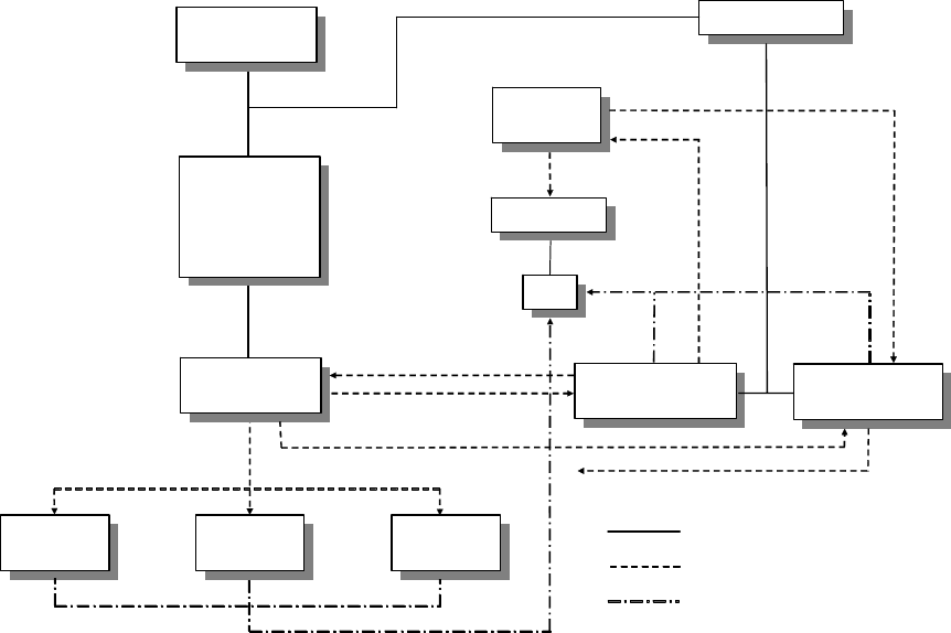
organizations that exist to manage spectrum, the service FMOs and the DSO. Day-to-day
operations and routine national and international matters are handled predominantly by these
organizations through their interaction in the permanent working groups of the MCEB
Frequency Panel (FP). In the next two sections, we provide greater detail on how these parts
of the DoD spectrum management organization interact in spectrum management planning
and spectrum management operations.
DASD for
Spectrum,
Space,
Sensors, and
C3
DASD for
Spectrum,
Space,
Sensors, and
C3
NII, Spectrum
Directorate
NII, Spectrum
Directorate
DISA Director
DISA Director
Air Force
FMA
Air Force
FMA
Navy
NMSC
Navy
NMSC
Army
ASMO
Army
ASMO
Defense
Spectrum Office
Defense
Spectrum Office
ASD NII/
DoD CIO
ASD NII/
DoD CIO
Joint Spectrum
Center
Joint Spectrum
Center
Joint Staff,
J6
Joint Staff,
J6
MCEB
MCEB
Strategic planning
WRC coordination,
SM issue coordination
Operational
guidance
Combatant
Commands
Policy guidance
Coordination, policy guidance
DSO
Chairs
MCEB FP
Technical Support to
all other organization
HNA
Support
Organizational relationship
Guidance, coordination, support
FP
FP
Participation
Figure 6-1. Organizations that cooperatively manage DoD spectrum
6.2 DoD Spectrum Management Planning Processes
Spectrum management is becoming ever more complex as a result of the increasing
demand for use of RF spectrum by commercial enterprises and governments worldwide.
Meanwhile, the current transformation of the Armed Services hinges on the exploitation of
communications and sensor technologies that rely on the use of RF spectrum thus
simultaneously increasing the quantity of DoD systems that use spectrum. In order to be
successful in this transformation, spectrum must be available globally. The DoD is actively
updating its spectrum policy and spectrum management procedures to address the changing
environment. Most notable in this transition is greater emphasis in planning to anticipate
spectrum needs, to mitigate the risks associated with the acquisition of new systems, and to
6-3
ensure suitable spectrum is available for future operations. We divide this planning into
three categories: strategic planning to ensure spectrum allocations both nationally and
internationally will support projected needs, supportability planning in the acquisition
process to ensure new systems can be supported with spectrum where their use is anticipated,
and operational planning to ensure spectrum is available in theaters of operations to support
deploying spectrum dependent systems.
6.2.1 Strategic Planning
Strategic planning involves projecting future communications requirements and then
developing a roadmap to ensure spectrum allocations, allotments, and regulations will
support those requirements. This activity is made difficult by the numerous demands for RF
spectrum from DoD, other government agencies, foreign governments, and foreign and
domestic commercial interests and the rapidly evolving technologies that use RF spectrum.
To be effective, strategic planners must be aware of DoD’s future needs and the capabilities
of new technologies that DoD intends on developing and other government and civilian
interests are trying to put in service worldwide. They must be engaged in the international
conferences and domestic debates that determine spectrum allocation and allotments. The
success or failure of strategic planning is manifested in how RF spectrum is allocated and
allotted, both internationally and domestically. Thus, strategic planning is executed by
developing an awareness of current and future technologies, identifying their RF spectrum
effects, projecting where the DoD needs access to spectrum and who is likely to encroach on
its availability, developing a plan to protect or to enable DoD capabilities through allocations
and allotments, and finally, participating in the forums that determine spectrum allocations
and allotments so that these plans can be implemented.
Allocation and reallocation activities are instigated to enable new services or additional
users. The reasons to initiate this process can be as many as there are new services, new
users, or new applications that use spectrum. The process from proposal to revisions in
tables of allocations and allotments can take years.
Spectrum allocations and reallocations, especially internationally, are arrived at by
consensus. To achieve consensus requires an understanding of the concerns of interested
parties, a thorough study of the problem, and full consideration of the technical alternatives.
Delegations at any level are most effective when they can effectively present technical
alternatives that will solve everyone’s needs. The iterative process of meeting, presenting
alternatives, and vetting concerns enables delegations to arrive at alternatives that are most
likely to achieve consensus. Thus, iterative meetings of interested parties separated by
periods of study and analysis, characterize the spectrum allocation processes. We see that
effective strategic planning is about solving everyone’s problems not just those of the DoD.
We divide our discussion of the processes of strategic planning into three activities: what
the DoD is currently doing to keep track of changes in technology and to project the future
6-4
issues of spectrum allocation and allotments; how the DoD participates in national forums
that determine spectrum allocations and allotments, and how they participate in international
forums concerning spectrum allocations.
6.2.1.1 Predicting Spectrum Allocations and Allotment Issues
The DoD learned a significant lesson in the recent reallocations of spectrum to
commercial wireless services. Nationally, it is not sufficient to simply identify which
systems will be displaced and the cost of relocating those services if the goal is to protect
DoD capabilities. Rather, it is necessary to articulate the ramifications of spectrum
reallocation in terms of lost capability both in the present and in the future. Similarly, if the
DoD needs allocations and allotments to support future needs it needs to articulate that
requirement in terms of capabilities that will not be available if these changes do not take
place.
In the process of studying spectrum support for new systems, DoD members may identify
potential benefits that can be obtained through a new allocation. The action taken would
depend on the frequency band of the allocation and where in the world the allocation would
be used. Since consensus is the objective, initiation of the process would require a strong
case supported by technical studies. If the proposal will only affect national allocations, then
the organizations that would be involved in the process would be NTIA for federal
government exclusive bands, the FCC if it affects shared bands, and Congress if a
reallocation between the national allocations is required. If the proposal will affect a
neighboring country, then it may be addressed through a bilateral agreement. If the proposal
will affect international allocations, then it would need to be proposed as an agenda item at a
WRC for future consideration. It can take years for changes to be made, with the number of
years being correlated to the number of organizations that would be involved in the changes
and the number of spectrum users that would be affected by the changes.
6.2.1.2 DoD Participation in National Spectrum Allocation Processes
There are three national entry points for introducing allocation proposals: NTIA, FCC, or
Congress. Allocation proposals are introduced within the IRAC of NTIA when a
government user has a new spectrum requirement. The FCC is made aware of these
proposals through their participation as an observer of the IRAC’s activities. The FCC will
introduce an allocation proposal by issuing a Notice of Inquiry (NOI) for fact gathering if
needed, or will issue a Notice of Proposed Rulemaking (NPRM) inviting comments from
interested parties. The FCC allocation process is open to the public and most proceedings
are also provided to the IRAC for comment via the FCC liaison per agreement between the
NTIA and the FCC. Congressional introduction of allocation proposals comes in the form of
legislation. This legislation will either direct the FCC to support a particular service or will
propose the shifting of federal government, non-federal government, and shared allocations
to enable the FCC to support a service. The perception that legislation is necessary results
6-5
from Congressional interaction with constituents and lobbyists. The option to realign
spectrum allocations is motivated by the perception that the FCC will not be able to support
the service with the existing non-federal government spectrum allocation and, recently, the
potential to obtain money through the sale of the realigned spectrum.
Of the three entry points for allocation proposals, the Congressional causes the greatest
concern since it can result in the greatest loss of spectrum and it generally avoids the public
scrutiny of the FCC’s open proceedings. FCC has authority over non-federal government
radio spectrum and can affect the use of shared spectrum. FCC actions can significantly
affect DoD spectrum use for both in-band and adjacent band systems. Government-initiated
proposals will necessarily consider DoD concerns since the DoD is represented in the IRAC
where these proposals are first vetted. Ensuring that DoD concerns are brought to bear in
Congressional actions requires being aware of the reasons for the proposals, identifying
alternatives, and being able to articulate the impact in terms of lost operational capability
resulting from the loss of the spectrum.
6.2.1.3 DoD Participation in International Spectrum Allocation Processes
International allocations are established and changed through the World
Radiocommunication Conferences (WRCs). Each WRC prepares an agenda for the next
WRC and the preliminary agenda for the WRC after next. These agendas contain the
proposals that ultimately lead to spectrum allocations and new spectrum sharing rules. In
preparation for the next WRC, the ITU-R either assigns the proposal to a Working Group
(WG) or creates a Task Group (TG) formed by members of its Study Groups to study the
technical and regulatory issues stemming from the agenda item. The result of these efforts is
a draft report to the next Conference Preparatory Meeting (CPM) to which all members of
the ITU-R consent. Task groups differ from working groups in that they are not permanent
but exist for WRC-related studies only. Participation in the TGs and WGs is open to ITU
member countries and ITU-R sector members.
National participation in these conferences is characterized by the recreation of the study
and task group organization formed in the ITU-R. There is a mirror group formed in the
ITAC-R organization of the DoS. Both the DoD and NTIA have an organization with the
specific purpose of preparing for international conferences—the Radio Conference
Subcommittee (RCS) of NTIA and the International Permanent Working Group (IPWG) of
the MCEB FP. Figure 6-2 illustrates the organizational structure. Issues are studied and
positions are prepared at each level. It is generally expected that for each meeting, a single
position be forwarded to the next level. Thus, the DoD members in the NTIA RCS would
present and support the DoD position formed in the IPWG and approved by the MCEB. The
federal government members of the ITAC-R would present and support the NTIA position
developed by the RCS. Finally, the delegation to international meetings, both regional and
worldwide, will support a position selected by the DoS/EB/CIP (see Section 5.3.2.) Several
meetings are conducted at each level. Each meeting at each level provides the participants
6-6
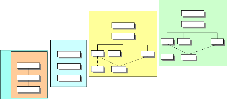
the opportunity to learn the current leaning of sister organizations or countries. The
exchange of technical information helps improve proposals so that a final consensus can be
obtained. Positions may be modified from meeting to meeting. The iterative international
meetings are also very important to smaller countries that do not have the resources to study
issues, as it gives them the technical information that enables them to take a position.
ITU-R
ITU-R
SG-1
SG-1
SG-3
SG-3
SG-9
SG-9
...
TG-1-9
TG-1-9
ITU
ITU
ITAC-R
ITAC-R
SG-1
SG-1
SG-3
SG-3
SG-9
SG-9
...
TG-1-9
TG-1-9
DoS/EB/CIP
DoS/EB/CIP
WG-1
WG-1
WG-1
WG-1
MCEB
MCEB
FP
FP
IPWG
IPWG
NTIA
NTIA
IRAC
IRAC
RCS
RCS
International
National
DoD
Federal Gov’t
NII
Figure 6-2. Organization to study allocation issues for WRCs
It is feasible for any qualified person to participate in an international meeting.
Individuals in DoD who want to participate submit their requests to NTIA, which forwards
them to CIP. The White House selects the final delegation to the international meeting. As
stated above, members of the delegation are expected to support the national position at the
meeting.
6.2.2 Planning for Spectrum Supportabilty
Due to the international reach of DoD spectrum use, finding the ideal spectrum for use
with a DoD system involves finding sufficient spectrum to support the operational needs of
that system in all the regions of the world where it will be used. The challenge in this task is
that most spectrum is already in use in most regions of the world. Additionally, spectrum
allocations, allotments, and assignments can vary from region to region, country to country,
even within national boundaries. It is the policy of the United States to respect the sovereign
rights of host nation administrations to manage the use of spectrum within their borders and
to not use spectrum without their approval. Finding spectrum that is equally available in all
countries where systems will be used by the DoD may not be feasible. The objective of
planning for spectrum supportability is to mitigate the risk of acquiring systems that cannot
6-7
be used where they are needed. Recent acquisitions are replete with examples where
supportability was not appropriately addressed. Most notable are the following:
The B-2 Bomber’s radar has a high probability of interfering with primary users in
the radar’s frequency band. It is currently being redesigned.
•
•
•
•
The Enhanced Position Location Reporting System (EPLRS) Situational Awareness
Data Link (SADL) cannot be used in Germany or Korea.
The Global Hawk SATCOM data links use exclusive non-government bands, which
means the Global Hawk can only be employed in the U.S. and its Possessions
(US&P) if it can operate in a non-interference mode with primary users of that
spectrum.
COTS Radio Frequency Identification (RF ID) systems were acquired that operated
in frequencies that precluded their use in some European countries.
These costly mistakes have been a primary motivator in current efforts to redefine DoD
policy and procedures with respect to the acquisition of systems that use RF spectrum.
Although certification and spectrum supportability have always been essential parts of
system acquisition, they are now receiving additional emphasis and being more integrated
with new acquisition procedures. Recent revisions in DoD policy on Electromagnetic
Spectrum – Management and Use (DoDD 4650.1) clearly demonstrates the significance with
the additional policy statement:
Spectrum-dependent equipment or systems shall not be developed or procured
without reasonable assurance that required electromagnetic spectrum is, or shall
be, available to support the development, testing, and operation of that equipment
or system.
This same directive puts greater emphasis on the responsibilities of the acquisition
community to ensure compliance with supportability requirements and to provide oversight
to this whole process prior to and through the developmental test and evaluation phase of the
systems. Meanwhile, the spectrum management organizations identified in Section 6.1 are
attempting to better assist the acquisition community through their efforts to anticipate the
needs of the acquisition community, to define how to do spectrum supportability, to train the
acquisition community in these processes, and to provide tools that can assist system
developers in the supportability task (see Section 6.4 for descriptions of these tools).
Supportability planning consists of multiple processes that try to engineer successful
acquisition. First the spectrum management organizations try to anticipate issues with new
technologies and services and to introduce them promptly so that they can address them as
early as possible in the strategic planning process. The remaining processes are either part of
or can be integrated with the acquisition process. In the subsequent subsections we describe
the activities that are undertaken to anticipate issues, we propose how spectrum
6-8
supportability could be integrated with the Defense Acquisition Management Framework and
the Joint Capabilities Integration and Development System (JCIDS), we describe the
components of spectrum supportability analysis, and then we present greater details on the
activities associated with spectrum certification and host-nation coordination.
Although this section focuses on processes that are part of spectrum supportability, it is
important to realize that spectrum supportability is not an end state but an assessment that
risk is sufficiently low that acquisition may proceed. There is no guarantee that a foreign
administration will continue to allow DoD use of the spectrum a system needs.
6.2.2.1 Keeping Track of Technological Innovation
As described in Section 6.2.1.1, the DoD Spectrum Management agencies are actively
engaged in learning the changes that are occurring in uses of spectrum and in the
technologies that are anticipated for DoD systems. The Emerging Technologies Division of
the DSO performs studies and commissions reports toward this end. There is active
engagement between all of the spectrum management organizations and the science and
technology and research and development communities. The goal is to allow those
knowledgeable in spectrum allocations to understand how new systems will use spectrum so
that they can assist the developers in identifying suitable spectrum to support the systems
and identifying those issues that must be addressed through strategic planning.
6.2.2.2 Integration with the Joint Capabilities Integration and Development System
(JCIDS) and the Acquisition Process
DoD’s goal is to integrate spectrum management processes into the JCIDS and
acquisition processes so that spectrum supportable systems are acquired. Figure 6-3
illustrates the acquisition framework and aligns it with the spectrum supportability activities
and the spectrum certification process. This proposal places the spectrum supportability
analysis and other tasks early in the process during the ‘capabilities definition’ phase, a time
when it can best influence system development to produce a spectrum supportable system.
A stated goal of the acquisition community is to exploit commercial off-the-shelf (COTS)
technologies. Although it is more cost effective to buy fully developed systems than to
develop them from scratch, this offers some critical challenges in the area of spectrum
supportability. It does not allow spectrum supportability to be addressed in the development
phase. Although systems can function, they may be designed for use in exclusive-use, non-
government bands, restricting DoD users to a non-interference basis, or they may be
designed to use frequency bands that are not available in the host nation where the
equipment’s use is intended. These potential constraints make it essential that COTS
systems also be certified and evaluated for spectrum supportability prior to acquisition. The
difference between a supportability analysis that precedes system development and a COTS
acquisition is that in the former this analysis can influence the success of an acquisition but
6-9
in the latter it will either prevent a failure or confirm the supportability of the system.
Current policy in DoDD 4650.1 dictates that:
No spectrum-dependent “off-the-shelf” system shall be purchased or procured
without the assurance that spectrum supportability has been, or can be obtained.
IOC
B
A
Concept
Refinement
System Development
& Demonstration
Production &
Deployment
Systems Acquisition
Operations &
Support
C
Sustainment
FRP Decision
Review
FOC
LRIP
Critical Design
Review
Pre-Systems Acquisition
Technology
Development
(Program Initiation)
D
o
D
I
5
0
0
0
.
2
S
p
e
c
t
r
u
m
P
l
a
n
n
i
n
g
Band Selection
Spectrum
Supportability
Analysis
Deployed Support
EMC Analysis
D
D
F
M
1
4
9
4
Stage I
Conceptual
Stage 2
Experimental
Stage 3
Developmental
Stage 4
Operational
Initial Capabilities
Document (ICD)
Capabilities Development
Document (CDD)
Start Host
Nation Coord
Concept
Refinement
Decision
E
3
Req
Definition
Freq
Assignment
Frequency Assignment
Host Nation Approval
Mitigation Measures
Frequency Assignment
ECP upgrades
and P
3
I
Stage 4
* Notes to Holders
Sustainment
Disposal
System
Integration
System
Demonstration
Full-Rate Prod &
Deployment
Delete
Freq
Asgnmt
EOA
DT&E
OA
* Documents changes
to the system
Capabilities Production
Document (CPD)
IOT&EIOT&E FOT&EFOT&E
Figure 6-3. Proposed alignment of spectrum supportability activities and spectrum
certification stages with the defense acquisition management framework
6.2.2.3 Spectrum Supportability Analysis
Spectrum supportability analysis assesses the risk factors affecting spectrum
supportability. It includes, as a minimum, assessments of
1. Battlespace performance.
This assessment considers the interaction of the system being acquired with other
systems that would be used in the same battlespace. It identifies whether these systems are
electromagnetically compatible. This assessment also considers whether the spectrum that
the system uses will provide the performance that is desired for that system
2. Planned operating locations.
6-10
This assessment identifies the regions of the world where the system will be used and
ranks the importance of those regions to each other. If different bands of spectrum can
partially support the complete list, the ranking helps identify which bands are most useful.
3. Host nation regulations and processes.
This assessment identifies the current allocations, allotments, and assignments of
spectrum in the proposed bands in the different regions of the world where use is anticipated.
It assesses the expected availability of spectrum support and the difficulty of getting approval
to use the system in those regions.
4. Future plans in worldwide allocations.
This assessment is forward looking at the current trends in spectrum use and attempts to
identify whether these trends may encroach upon the availability of the spectrum intended
for the system to use.
6.2.2.4 Spectrum Certification (DD FM 1494/J/F-12 Process)
Spectrum certification is a mandated process to ensure that: (1) the operational
frequency band(s) and type of services are in conformance with respective national and
international tables of frequency allocations; (2) the equipment conforms to applicable
standards, specifications, regulations, directives, and statutes, and (3) approval is provided to
authorize expenditure of funds for the procurement/development of RF dependent
equipment. DoDI 5000.2 directs that spectrum certification is required for a Mile Stone
(MS) B decision or MS C decision if there was no MS B decision. All spectrum dependent
equipment/systems owned and operated by the DoD require spectrum certification.
Equipment spectrum certification is supported by the MCEB FP Equipment Spectrum
Guidance Permanent Working Group (ESGPWG) and the NTIA Spectrum Planning
Subcommittee (SPS) and Frequency Assignment Subcommittee (FAS). Figure 6-4 illustrates
the spectrum certification process.
6-11
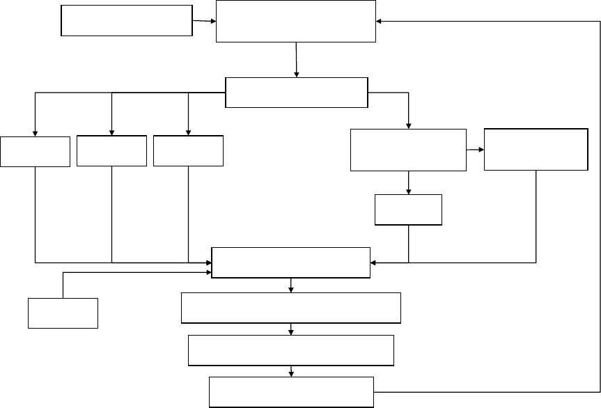
CONTRACTOR
(Generate DD Form 1494)
PROGRAM OFFICE
(Submit DD Form 1494 and
Releasable DD Form 1494 Data)
SPONSORING MILDEP/FMO
(Review and Submit)
NTIA/SPS
(Comments)
JSC
(Comments)
ESG PWG
(Comments)
MCEB
(Distribute releasable
DD Form 1494)
COCOM/HN
(Comment)
CCEB and
MEMBER NATIONS
(Comment)
MCEB ESG PWG
(Prepare guidance and review)
ESG PWG STEERING MEMBER
(Approval guidance)
IRAC
(Comments)
MCEB (JSC)
(Distribute guidance)
SPONSORING MILDEP/FMO
(Appropriate action)
DD Form 1494 Releasable DD Form 1494
CONUS
OCONUS
Figure 6-4. The spectrum certification process
Program managers initiate spectrum certification with the submission of a DD Form
1494, Application for Equipment Frequency Allocation, to the frequency management office
of the pertinent military service: for the Army, The Army Spectrum Management Office
(AMSO); for the Air Force, the Air Force Frequency Management Agency, (AFFMA); and
for the Navy and Marine Corp, the Navy Marine Corp Spectrum Center (NMSC). This
application must be coordinated through the FP of the MCEB before funds are authorized for
the development of any new equipment that will radiate electromagnetic energy. An
application is also required for equipment receiving RF, if protection is desired. An
approved DD Form 1494 establishes that a particular system has a valid spectrum
requirement. The approved DD Form 1494 is later used for frequency assignment. The FAS
of the IRAC must assign a frequency for any transmitting equipment prior to its operation.
Additionally, the applicant must coordinate with the local frequency manager in the proposed
area of deployment.
The DD Form 1494 is submitted at four different stages of an acquisition program and
the process repeats itself for each. The purposes of these submissions follow:
6-12

Stage 1. Planning or Conceptual: Advises on feasibility of getting spectrum support and
recommends modifications or changes in frequency bands needed to get spectrum support.
Stage 2. Experimental: Provides guidance for assuring spectrum support in later stages, and
is needed before obtaining frequency assignments for experimental testing.
Stage 3. Developmental: Provides guidelines for assuring operational spectrum support
needed before obtaining frequency assignments for developmental testing.
Stage 4. Operational: Certifies availability of spectrum support needed before making
operational frequency assignments.
Each Service provides lead times for submission of the DoD Form 1494. As a general
reference, Table 6-1 provides the guidelines specified in Air Force Instruction (AFI) 33-120.
Table 6-1. DD Form 1494 submission lead time guidelines from AFI 33-120
10
Acquisition Lead Times
Stage Space Systems Other Systems
Planning or
Conceptual
Not earlier than seven years and not later
than two years before satellite launch
Not less than one year before the planned
date of initial operation
Experimental
No later than four years before satellite
launch
Not less than one year before procuring
equipment
Developmental
No later than three years before satellite
launch
Not less than one year before award of a
developmental contract
Operational
No later than two years before satellite
launch
At least six months for all other equipment if
there are only minor changes from previous
stage submissions; one year for significant
changes
The spectrum certification process is not equivalent to spectrum supportability. All it
checks is conformance to regulatory requirements. It does not ensure spectrum availability
nor grant frequency assignments. It does not include host nation coordination nor the
analysis that evaluates the risk of other users encroaching on the spectrum requested.
10
These lead times are shown as an example. Although they were derived from the latest AFI, recent changes
in the acquisition processes require they be changed.
6-13
6.2.2.5 Host Nation Coordination
The responsibility for host nation coordination falls under Outside CONUS (OCONUS)
geographical area combatant commands. Each combatant command has a small staff
element, their Joint Frequency Management Office (JFMO), to coordinate this host nation
spectrum support. Effective coordination requires both the spectrum management and
acquisition communities to assist these staffs in this effort. Thus the effort to evaluate
supportability increases with as many combatant commands that will use the new system and
the number of countries that the system will be used in.
Ideally, the host nation coordination results in nations assisting the combatant commands
in finding the best spectrum to use and committing to its availability when the system is
finally developed and deployed. However, host nations have their own processes and in
some cases do not do certification or require that assignments be given within 90 days after
certification. There is even a new trend where host nations provide “horizon dates” for
certification that put time restrictions on their commitment to accommodate the new system.
Host nation supportability is an area of great risk in system acquisition.
6.2.3 Operational Planning
Operational planning is the planning that precedes major operations in a theater.
Characteristics of this planning are efforts to:
1. Identify the spectrum that is needed for the operation.
Identifying spectrum need includes making an inventory of spectrum dependent systems
and identifying the bands and quantity of spectrum needed to achieve the capability desired.
This process is complicated since a large part of the planning process involves building a
communications plan that can support communications requirements. Spectrum needs are
identified as the plan is being developed which can proceed up to the start and through
operations.
2. Coordinate the specific availability of spectrum from host nations.
Again, host nation coordination is the responsibility of the combatant commands. Due to
the visibility of these types of operations additional diplomatic support is usually available.
Thus, effective host nation coordination requires synchronization of several parts of DoD and
the government to articulate the same requirements.
3. Divvying the spectrum among users and the systems that use spectrum for optimum
capability.
Upon getting spectrum for operations there is a process of prioritizing who and what
systems get to use the spectrum and where. The process of prioritizing users of spectrum
will naturally result in identifying shortfalls that are operationally critical. These results feed
6-14
into 1 above. Operational planning is a cyclical process that continuously attempts to build
the capability needed by DoD for an operation.
6.3 DoD Spectrum Operations (Assignments)
Frequency assignment rather than allocation is the more common spectrum management
process. Generally, users of spectrum attempt to fit their use into bands that are already
allocated. The challenge is that these bands are already heavily used and any new uses either
require that the new users not affect established users or that the old users give way.
Frequency assignment can be of two types, those that accompany the acquisition of new
systems and those that identify channels that existing systems can use.
Spectrum operations consist of coordinating the assignment of frequencies for use with
existing equipment in support of military operations and training. The presumption is that
the equipment used by the Services can be assigned some portion of the spectrum in the
geographic region in which it will be employed. Obtaining assignments, or a license to
operate, involves coordination among users and with the local frequency management
offices. In the following subsections, we describe the basic procedures users follow to
acquire frequency assignments for their equipment.
6.3.1 Continental United States (CONUS)
Operations in CONUS have two characteristics. First, spectrum allocations, allotments,
and assignments are established and planning involves working within these bounds.
Second, if spectrum needs extend beyond the established assignments, the national spectrum
management organizations—the FCC and NTIA—must get involved.
6.3.1.1 Installations and Ranges in the US&P
Installations and ranges usually have some set of frequencies assigned for use in their
geographic area. Thus, installations and ranges normally have an office that manages the use
of these assigned frequencies. Users that want to operate equipment on these facilities must
coordinate with the installation spectrum management office on the installation. If the
existing frequencies of the installation cannot service the user’s needs, the installation
spectrum management submits the requests to its major command.
6.3.1.2 United States and Possessions (US&P)
When military organizations plan to operate equipment off an installation but within
range of an installation, they must coordinate the use of frequencies with the area frequency
coordinator (AFC). There are eight AFCs, each manned by one of the Services, and each
responsible for a geographic area. The AFCs are responsible to their military department for
administrative purposes and to the MCEB for policy guidance. The AFC’s role is to ensure
spectrum use will not interfere with any installation’s spectrum-dependent system.
6-15

The Federal Aviation Administration (FAA) is responsible for operation of the air traffic
control system. It has been provided several bands of frequencies for this task that are listed
in Table 6-2. Military organizations that want to use frequencies from this list must
coordinate their use with the FAA.
Table 6-2. FAA frequencies and bands
190 - 285 kHz 285 - 435 kHz 510 - 535 kHz
74.8 - 75.2 MHz 108 - 121.9375 MHz 123.5875 – 128.8125 MHz
132.0125-136 MHz 328.6 – 335.4 MHz 978 – 1020 MHz
1030 MHz 1031 – 1087 MHz 1090 MHz
1104 – 1146 MHz 1157 – 1213 MHz 1215 – 1400 MHz
2700 – 2900 MHz 5000 – 5250 MHz 9000 – 9200 MHz
Regular frequency assignments and temporary assignments for greater than 90 days that
operate near the Canadian border are coordinated by the IRAC with the Canadian
Government. Assignments for less than 90 days are coordinated by the service SMO and the
Canadian National Defense Headquarters.
6.3.2 OCONUS Permanent/Fixed
When operating in another country, users of frequencies coordinate through their major
commands to the appropriate Service component in the theater. The service forwards
frequency requests per theater directives. Each country specifies their own procedures for
assigning frequencies. The Combatant Commander is responsible for coordinating
frequency support with these host nations.
6.3.3 Battlespace Spectrum Management (BSM)
Battlespace spectrum management has many of the characteristics of operational
planning; spectrum is identified for use in an operation and then divvied to users in order to
achieve the most capable fighting force. The scope of our description of BSM includes all
processes that manage spectrum use in a theater. BSM has four characteristics: allotment of
spectrum, decentralization of frequency assignment, identification of restricted frequencies,
and methods to resolve interference problems when they occur.
A Joint Task Forces (JTF) is normally created for missions with limited objectives. It
includes a full staff for planning and managing operations. Within the J-6 staff element, the
Command, Control, Communications, and Computer Systems Directorate, is the JTF
Spectrum Management Element (JSME). The JSME’s primary function is to ensure that
assigned JTF military forces are authorized to use sufficient spectrum to execute their
6-16
designated missions. It is the Joint Forces Commander who is responsible for assigning
frequencies; however, this is normally delegated to the JSME. In turn, the JSME may further
delegate this responsibility to subordinate commands. The JSME begins the process by
identifying the spectrum requirements and the spectrum that is available. As described in
Section 6.2.3, this may require extensive coordination with host nations. The JSME then
allots spectrum to the different subordinate commands considering their relative
requirements, the spectrum available, and the geographic distribution and transmission
characteristics of the assets that will use the spectrum (spectrum may be spatially reused).
Given their allotments, subordinate commands assign frequencies to spectrum users. These
assignments are made using the Revised Battlefield Electronic Communications Electronics
Operation Instruction (CEOI) System (RBECS) (see Section 6.4.1.3). These assignments are
made with the same considerations used by the JSME to allot the spectrum. The subordinate
commands then provide the JSME with their CEOIs and an assessment of specific
frequencies that are most critical to their operations. The JSME consolidates the CEOIs into
a Joint CEOI (JCEOI), considers the critical frequency information from the subordinate
commands, the critical frequencies of the host nation and other spectrum users and produces
a Joint Restricted Frequency List (JRFL). The JFRL consolidates and classifies the spectrum
uses that are most critical to operations and to the host nations. The JFRL is provided to the
electronic warfare components so that they can avoid jamming or otherwise interfering with
critical friendly systems.
All frequency assignments and restricted frequency information is consolidated into a
database using the Spectrum XXI tool (see Section 6.4.1.1). This tool helps identify
assignment conflicts. If there are conflicts with assignments, the spectrum managers of the
subordinate commands or Service components will try to resolve the issue among
themselves. Such resolution may involve changing frequency assignments, separating the
users of the conflicting assignments, making a time sharing arrangement, or using some
technical fixes if available. If resolution cannot be achieved by one of these means, meaning
the only solution is for one user to defer to the other, that decision rests in the hands of the
higher commander. Usually, the authority to make the decision is delegated to the
commander’s operations (J3) staff. The J3 makes the decision by prioritizing the capability
or the significance of the missions that the spectrum supports.
Inevitably, some systems that use spectrum may suffer interference. This interference
can come from another friendly source, a host or neighboring nation source, or an enemy
jammer. The DoD has a Joint Spectrum Interference Resolution (JSIR) process that is used
in both tactical and garrison scenarios. The user of the system that suffers interference
initiates the process by describing the effects. The JSIR process first tries to identify the
source and the location of the interfering system with actions depending on who and what the
source is. If the source is a friendly spectrum user, efforts to resolve the interference are the
same as those used to resolve assignment conflicts.
6-17
More detailed discussions of the processes used by DoD for tactical spectrum
management can be found in CJCSM 3320.01A and for interference resolution, in CJCSM
3320.02. ACP 190(B) provides greater detail on spectrum management in combined
operations.
6.4 DoD Spectrum Management Systems and Tools
As described above and throughout this document spectrum management is quite
complex and is more challenging to DoD than other government agencies and national users
due to its global scope . The vast number of administrations that affect spectrum availability
and the great demand and need that DoD has for spectrum requires the compilation of vast
databases of the worldwide use of spectrum. Also unique to the DoD is the availability of
automated tools to assist in the spectrum management task. Below we provide brief
descriptions of the purpose of a number of present and future tools. The vision within the
DoD is to provide an overarching tool that will assist the acquisition community and
operational planners in identifying the availability of spectrum worldwide. We first describe
individual tools and then the objective overarching spectrum architecture.
6.4.1 Spectrum Management and Supportability Tools
Many spectrum management tools already exist to support DoD spectrum management.
Their functions cover a number of spectrum management activities.
6.4.1.1 Spectrum XXI
Spectrum XXI is the joint standard DoD spectrum management system. It is used to
create, modify, renew, and delete permanent/temporary frequency assignments/proposals
worldwide. All DoD spectrum managers coordinate their assignments through Spectrum
XXI , which provides a real time view of all DoD frequency assignments worldwide. It also
includes information on host nation assignments. This database subsequently supports
interference analysis to determine who could be causing interference, and electronic warfare
deconfliction to assess whether jamming activities will interfere with friendly forces or host
nation frequency assignments . Spectrum XXI includes a propagation modeling tool that
enables the assessment of the range of impact of transmissions from an RF emitter.
6.4.1.2 Spectrum Certification System (SCS)
SCS is a database maintained by the JSC that serves as the central archive repository for
all DoD spectrum certification system data. The DD Form 1494 data is entered into this
database after completion of each stage of the certification process.
6-18
6.4.1.3 Revised Battlefield Electronic CEOI System (RBECS)
RBECS is a PC-based tool that gives major commanders near autonomy in the generation
of CEOIs. CEOIs provide guidance on the periodic changing of frequency assignments and
call signs by users. The purpose of these changes is to support communications security by
thwarting enemy efforts to direction find and to jam. An additional purpose of the CEOI is
to provide a directory of users.
6.4.1.4 Army Communications-Electronic System (ACES)
ACES is a modular system that provides Cryptonet Planning, Electronic Protection (EP)
and frequency planning, as well as the Army Signal Operating Instructions and the Joint
Communications Electronic Operating Instructions.
6.4.1.5 Joint Automated Communications Systems (JACS)
JACS is an application that produces a Joint CEOI. JACS has been selected to replace
RBECS.
6.4.1.6 Host Nation Spectrum Worldwide Database (HNSWD)
HNSWD automates the process of host nation support. It contains a database of
historical and current host nation support actions. Warfighters can use this system to identify
spectrum that is likely to be available and then to make a request for it. Acquisition
managers can use it to find bands of spectrum that have been supported by host nations in the
past, so they mitigate the risk of acquiring unsupportable systems.
6.4.1.7 Warfighter Spectrum Usage Planning Tool (WSUPT)
WSUPT supports planning by providing assessments of RF spectrum demands for
different courses of action. It provides “ballpark” estimates of spectrum usage in bandwidth
and then enables users to dynamically assess changes in usage that result from changes in
plans.
6.4.1.8 Defense Spectrum Supportability System (DS3)
DS3 is the next generation spectrum certification system supporting spectrum
management from acquisition through operations. It has a spiral development cycle that will
have up to seven increments that will incorporate global spectrum awareness, regulatory
awareness, spectrum trend analysis and metrics, and support for emerging technologies.
6-19
6.4.1.9 Acquisition Community Connection (ACC) Spectrum Special Interest
Area/Community of Practice Website
The ACC website provides guidance on a number of acquisition topics. DSO maintains a
Spectrum Special Interest Area /Community of Practice website accessible for the ACC. The
spectrum area has documents on a variety of spectrum topics, including spectrum planning,
spectrum supportability, spectrum certification, and E3. It provides an arena for discussion
between the spectrum community and the acquisition community, as well as an information
portal for program managers and operational spectrum units. The website can be accessed
through http://acc.dau.mil/simplify/ev_en.php by selecting the spectrum compliance topic in
the list of special topics or by going directly to
http://acc.dau.mil/simplify/ev.php?URL_ID=11213&URL_DO=DO_TOPIC&URL_SECTION=201.
6.4.2 Overarching Spectrum Architecture
The vision for future spectrum management is to develop a single architecture for all
spectrum management and engineering processes. This vision is the foundation of the
Global Electromagnetic Spectrum Information System (GEMSIS), which is in the initial
stages of capability definition. It will provide a “network-centric” view of these processes.
It will provide support for all operational, acquisition, and regulatory spectrum management
processes, essentially consolidating all the functions of the systems described above in one
place and providing additional features relevant to spectrum management. It is intended that
GEMSIS will be fully integrated into the Global Information Grid (GIG), thus providing the
network-centric environment that will extend the full functionality of the system to the
battlefield user and enable a real time worldwide view of spectrum usage.
6.5 Summary
Procedures for managing the use of spectrum on an operational basis are well developed
and tested routinely. The vast number of actors and interested parties in these processes, the
technical complexity of equipment that uses RF spectrum, and the rapid changes in
technologies that use spectrum make spectrum management very complex. The most
difficult challenges in DoD spectrum management are in the strategic planning for the
acquisition of new systems. Unique in DoD spectrum management is its global scope.
These factors make active and innovative leadership in strategic planning and policy a
necessity. DoD is meeting these challenges. It has taken steps to anticipate the changes that
are occurring in spectrum usage and to modify its spectrum management processes to
proactively address these changes. DoD is a leader in developing methods and tools to
support spectrum management.
6-20
Section 7
Technological Advances and their Impact on Spectrum
Management
Spectrum management has been based on our earliest understanding of how signals are
modulated and sent. As presented in Sections 1 and 3, the method used to manage spectrum
has involved the isolation of users in frequency band, in location, and in time. Advances in
communications technology have provided a myriad of additional dimensions to the problem
and in some cases this paradigm is no longer suitable. To present these advances, we divide
the topic up according to the objectives of the technology. We broadly define the objectives
as information efficiency, spectrum efficiency, digital signal processing, spatial reuse, and
dynamic spectrum management.
The relative improvement that is achieved by these technologies is very dependent on
how one measures the effective use of spectrum. We note that the choice of any particular
metric of spectrum efficiency will tend to favor one solution over another. For example,
measuring the ability of a particular solution to send the most bits of information in the
narrowest band of spectrum may not capture its vulnerability to hostile actions, which would
make it undesirable for military use. Measuring the use of spectrum over time may
underestimate the military’s requirements where short intense use periods that occur during
military actions and training are separated by longer periods of routine operations where use
of spectrum is substantially less. Assigning spectrum based on average use may keep the
military from having enough spectrum to perform its most important missions. Throughout
our discussion of these technological advances we attempt to identify the tradeoffs involved
in using each technology.
Finally, these technological advances can improve the use of spectrum; but using them
would require a reevaluation of the methods used to manage it. These technologies enable
and, in many cases require, flexibility in how spectrum is managed in order for there to be
any advantage. We conclude this section with a discussion of spectrum management models
and describe how these models, and also regulation, promote one solution over another.
7.1 Information Efficient Technologies
When speaking of information efficient technologies we are referring to technologies
used in digital communications that reduce the number of bits required to send information.
These technologies consist of techniques to encode information, to reduce data redundancy,
and to compress data. Included in these technologies are methods to correct errors. Errors
occur in communications and in most cases need to be corrected. Correction methods also
have different levels of efficiency that are a function of the number of bits sent.
7-1
7.1.1 Source Coding
Source coding is the conversion of an analog signal into a stream of bits. There are two
basic methods for converting the analog signal. The first is waveform encoding. In
waveform encoding, the information signal is sampled and each sample is recorded into a
finite number of bits. The second method is model-based source coding. In model based
source coding a mathematical model for a filter is used as the basis of information signal
encoding. The information signal is converted into parameters for the model and a low rate
excitation signal. This is what is transmitted. These modeling techniques can greatly
increase the efficiency of encoding. For example, a voice stream in the public switched
telephone network (PSTN) uses waveform encoding resulting in a 64 kbps stream. The
coding technique used in the current Code Division Multiple Access (CDMA) cellular
telephone standard uses a model-based approach that encodes speech into a variable rate
signal that varies from 1 to 8 kbps. In the worst case this system uses 1/8
th
the bandwidth
used by PSTN.
Source coding is lossy, meaning some information about the signal is usually lost in the
process of coding. Thus, different source coding techniques may reduce bandwidth but in so
doing sacrifice fidelity. For example, consider encoding techniques for pictures. Pictures
can be arbitrarily reduced to smaller file sizes by making each pixel stored in the file
represent a larger portion of the picture; however, this results in less picture resolution.
Thus, the selection of a source coding technique must consider whether the resulting output
will meet the requirements of the intended use.
7.1.2 Redundancy Reduction
Reducing the redundant transmission of information reduces the quantity of bits sent.
For example, a video encoder may send only a subset of the bits that define a picture frame,
restricting the data sent to the bits defining the portion of the picture that changes between
frames. In a voice system, silent periods that occur naturally in conversations may be
skipped and not transmitted. If done well, such reduction techniques will present no
perceivable difference in information quality.
7.1.3 Data Compression
Data compression reduces redundancy but just with knowledge of the bit stream. That is,
a block of bits is reduced to a smaller set of bits through some algorithm that allows for exact
lossless replication of the original block of bits when an inverse algorithm is applied.
Programs that convert computer files to and from compressed ZIP files are examples of
applications using compression technology. Standard telephone modems use compression to
increase data transfer rates.
7-2
7.1.4 Error Correction
Data transmissions and encoded analog signals have different requirements for errors.
Generally, data transmissions cannot tolerate errors but real time streams such as voice and
video can. Additional bits are added to digital messages to detect errors. These methods can
be made better than 99.9% effective at identifying errors. Errors in data signals can be dealt
with in two ways. The data can be divided into small packets which are repeated if they are
received in error or the data can be encoded with additional bits such that errors can be
corrected at reception. This latter technique is referred to as forward error correction (FEC).
There are several factors that influence the decision on what technique to use, such as how
noisy the environment is and whether acknowledgements are used in the access protocols.
Even in systems with FEC, data packets may still need to be repeated if errors exceed the
capability of FEC to correct them.
Source coded signals are usually real time streams. If delays are tolerable, i.e., the voice
and video streams are not supporting a two way conversation or a teleconference, then signal
buffering together with the retransmit mechanism can be used to handle errors. The buffer at
the output contains space for some signal duration allowing time for retransmissions of
packets with errors without a resulting jitter in the output. In cases where the stream
supports a conversation or control function, such buffering is impractical. For example, the
rule of thumb for telephone conversations is that the maximum end-to-end delay should be
less than 200 msec. With an 8 kbps coding method, building a 48 byte packet will introduce
48 msecs of delay. Additional delays occur in accessing the channel, in transmitting the
packets, and in processing packets across each link of the connection. Buffering would
require accepting further delays. The delay budget is unlikely to allow a reasonably sized
buffer. For this reason, errors in real time streams are either ignored or protected with FEC.
One observation of the source coding techniques is that bits are not created equal. For
example, if waveform encoding is used, the most significant bits are most important. To
understand the significance of bits, just consider an 8 bit number. An error in the most
significant position would be a difference of 128, while an error in the least significant
position would be a difference of 1. The most significant bit is 128 times more significant
than the least significant bit. Model-based encoding also has bits that are more significant.
The bits of the model parameters would have greater significance than bits of the excitation
signal. The choice of whether to use FEC or to allow errors is dependent on how vulnerable
the encoded signal is to errors. The greater the significance of some bits can result in the
overall signal being more vulnerable. It is common practice to protect the more significant
bits with FEC while not protecting the less significant bits. FEC is used closely with source
coding techniques to balance efficiency with the desired quality and reliability of the signal.
7-3
7.2 Spectrum Efficient Technologies
Spectrum efficient technologies seek to send information using the least spectral
bandwidth possible. We identify three types: advanced modulation techniques, pulse
shaping, and better receivers. Although these techniques offer greater efficiency, they tend
to be more vulnerable to noise and interference. They are especially vulnerable in hostile
environments because they are easily detected, intercepted, and jammed. See Section 7.4,
Spatial Reuse Technologies, for the alternatives. It is very important that these differences
be understood as they form the basis of disagreement between civil users and defense users
as to what is the most efficient way to use spectrum.
7.2.1 Advanced Modulation
In Section 1.2 we described modulation and stated that through modulation information
is transferred to a signal. We defined three features of a sine wave that may be changed, the
frequency, the phase, and the amplitude. We stated that each combination of characteristics
used in the modulation techniques is referred to as a symbol and that each symbol can
represent multiple bits depending on the number of symbols used in the modulation scheme.
Advanced modulation schemes attempt to achieve spectrum efficiency by increasing the
number of distinguishable symbols a sine wave can carry. The tradeoff for increasing the
number of symbols is that as the number of symbols increase they become harder to
distinguish, and noise and interference are more likely to cause them to be misinterpreted.
Since symbols represent multiple bits, an error in symbol detection can mean multiple bits
are incorrectly detected.
In digital communications systems, the occurrence of errors in bursts results in the use of
additional techniques to mitigate errors. Interleaving (mixing the bits up before transmission
and then unmixing them at reception) is used to reduce the effect of errors occurring in
bursts. Thus, errors that occur in bursts during transmission are distributed throughout a
packet after reception enabling FEC to be more effective. So FEC, in addition to being used
with source coding, is also used with channel encoding. As the data rates of the modulation
scheme increase so do the probabilities of error. FEC coding and modulation combinations
are used to achieve reliable transmission while keeping spectrum use efficient.
7.2.2 Pulse Shaping
The spectral content of a signal, i.e., the bandwidth it requires, is related to how the
signal changes states. Generally, with digital signals, the more abrupt and drastic the change
in a signal the greater its spectral content. Reducing spectral content involves designing the
signals to gradually change between states. This can be done by shaping the pulse or by
allowing the signal to change its characteristics less drastically. Figure 7-1 illustrates a
shaped pulse and how the spectral content is affected. Digital signals using multiple symbols
can be made to use less bandwidth by allowing time for a gradual change between states.
7-4
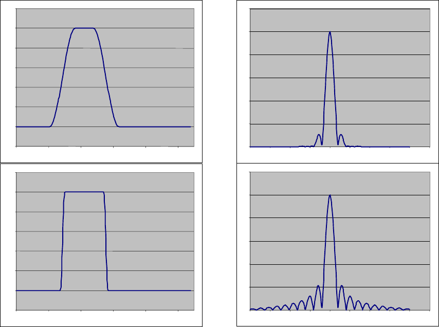
-0.2
0
0.2
0.4
0.6
0.8
1
1.2
0 1020304050
0
10
20
30
40
50
60
0 50 100 150 200 250 300 350 400 450
-0.2
0
0.2
0.4
0.6
0.8
1
1.2
0 1020304050
0
10
20
30
40
50
60
0 50 100 150 200 250 300 350 400 450
Figure 7-1. Comparison of the spectral content of pulses that change gradually vs.
rapidly. The pulse in the time domain is shown on the left and their use of spectrum is
shown on the right.
7.2.3 Receiver Capability
Our focus so far has been on transmission technology. Since the effects of interference
happen at receivers, their design also affects the capability of radio communications.
Specifically, receiver design can determine how large a noise floor a signal must overcome
and how much interference transmissions on adjacent bands will cause. The circuitry of
receivers introduces noise. If the receiver is noisy, then received signals must be stronger.
As receivers become less noisy less transmission power is required. The selectivity of a
receiver determines the band of frequencies that it passes to demodulation. As receivers
become more selective, the perceived interference from adjacent bands decreases. Adjacent
channels can be placed closer together. It is this latter improvement that contributes to
spectrum efficiency.
7-5
7.2.4 Tradeoffs
As described in Sections 7.2.1 and 7.2.2, three different signal features—frequency,
phase, and amplitude—are managed to achieve the most efficient waveform possible.
Waveforms with multiple states are designed to increase the rate at which a modulated signal
can transmit data. Meanwhile FEC decreases the rate of information transmission (i.e., more
bits are used to send the information) for the sake of reliability, and waveform shaping
techniques are used to reduce the actual spectrum used by the waveform with the tradeoff of
reducing the rate at which symbols may change. The combination of these three methods is
balanced in the attempt to reliably send the greatest number of bits per spectrum use.
Assuming these techniques are successful, the signal will occupy the narrowest band of
frequencies possible. This means that the transmitted signal has most of its energy within a
narrow band of frequencies. Thus, the signal is easy to detect, intercept, and jam. It also has
less diversity, which makes the signal more susceptible to environmental effects such as fast
fading, as described in Section 1.4.6.
The DoD is currently exploiting these technologies to improve the efficiency of its non-
tactical assets. Spectrum is being refarmed by converting older and wider bandwidth channel
to multiple narrower bandwidth channels. This administrative process is called narrow-
banding. It affects spectrum users in the 138-150.8 MHz , 162-174 MHz, and 406-420 MHz
bands.
7.3 Digital Signal Processing Technology
The classical methods of generating and transmitting signals have used devices and
circuits to isolate signals. The challenge in designing these circuits is that their performance
is frequency dependent. Although this is quite suitable for transceivers that use just one
frequency, transceivers that operate on multiple channels cannot be so well tuned on any one
of them for the sake of operating on all of them. Spectrum management responded to these
limitations by increasing the separation of channels. Additionally, for various reasons, these
transceivers may only operate over a small band of channels. Digital systems operate in a
different manner. Rather than isolating the signal with a circuit, the signal is isolated using
digital signal processing (DSP). In other words, the frequency content and the modulation of
the signal is synthesized through mathematical operations while in a digital form.
Conversions to and from the waveform that is used for transmission occur in digital-to-
analog (DA) and analog-to-digital (AD) conversion circuits respectively. The ability to
isolate and process signals is no longer dependent on the quality and the tuning of circuits,
but rather on the resolution and speed of the AD and the DA conversion and the speed at
which the digital signal processing can be executed. Such systems can also operate over a
wide band of frequencies.
Radios based on this digital technology have ushered in new concepts of how radio
communications can be executed. First, DSP enables the more efficient use of frequency as
7-6
a signal characteristic for defining different symbols of a modulated waveform. Second, the
radio becomes more generic, enabling a single radio to emulate many different types of
systems. We provide greater details in the next two subsections. In later sections we will
describe how these advances enable more dynamic use of spectrum.
7.3.1 Identifying Frequency Content
In classical radios, filter circuits are tuned to allow some band of frequencies to pass and
to attenuate all the others. The passed frequency band is then acted on by the remaining
circuitry, which has been specifically designed to demodulate the expected signal. Although
frequency is used as a modulation characteristic, these circuits are designed to provide a
single output for whatever instantaneous frequency is observed. To classify the full
frequency content of a signal would require taking a very narrow bandpass filter (i.e., a filter
that allows a very narrow band of frequencies to pass) and sweeping it across the frequency
band of the incoming signal and measuring the amplitude of the signal as it sweeps. This is
impractical in a real time system. With DSP, all of this can be executed digitally. The Fast
Fourier Transform (FFT) algorithm can convert a digitized analog signal to its frequency
content. So the views of the signal shown in Figures 1-1b, 1-2b, 1-5, and 1-6 can be
generated. This capability can be exploited in two ways: it enables new methods of
modulation where signals are created by combining frequencies, and it enables the
identification of unused spectrum for possible exploitation. We discuss the first technique
below and will discuss the relevance of identifying unused spectrum in Section 7.5.
The technique of using multiple frequencies to communicate is sometimes referred to as
tone multiplexing. The most common version of this technique is known as Orthogonal
Frequency Division Multiplexing (OFDM). OFDM uses some number of frequencies to
synthesize a waveform. (i.e., the single frequency signals are added to make the transmitted
waveform.) These single frequency signals are separated precisely from each other so that
during the period of detection, they do not interfere with each other. (Their spectrums
overlap each other but the precise timing of the signals over the signal duration prevents
them from interfering with each other.) This is the meaning of the word orthogonal. Each
frequency used in the waveform corresponds to a bit. For example, if the synthesized
waveform has the frequency, then the bit is one. It is 0, otherwise. So a received signal is
checked for frequency content and this correlates directly to a digital word. One popular
standard using OFDM uses 64 different frequencies; thus, each symbol represents a 64-bit
word.
OFDM signals have great diversity. Each of the frequencies will react with the
environment differently. In complex propagation environments where fast fading is likely,
some of the frequencies will suffer interference and others will not. This is actually a
feature. Some portion of the signal will usually get through to the receiver. The application
of FEC coding can make this a relatively reliable modulation technique for hostile
environments.
7-7
7.3.2 Software-Defined Radio
With the observation that all aspects of signal modulation can take place using DSP
comes the additional observation that all radios can be defined in the software that defines
the DSP algorithms that are used. Radios that are designed to exploit this fact are called
software-defined radios (SDR).
Current methods of frequency management have traditionally resulted in the
development of radios to work within a relative small band of frequencies. SDR works on
the concept that the frequency of operation and the modulation technique are not necessarily
defined at the time of manufacture but can be defined later in software. The attraction to
SDR is that it can be designed to work with legacy systems so they can be replaced in an
evolutionary way. Once all legacy systems are replaced with an SDR, then all the SDR
systems can be upgraded to more efficient modulation schemes and/or can be shifted to
operate on a completely different band of frequencies. All of these changes can be achieved
by simply changing the software. The JTRS is an SDR.
7.4 Spatial Reuse Technologies
Spatial reuse technologies attempt to increase the number of users of the same spectrum
either in the same geographic location or in close proximity to each other. These techniques
achieve spatial reuse by either limiting the area across which signals propagate, thus enabling
more users, or by using the diversity that exists between signals because of differences in
how and where they were transmitted, enable the simultaneous use of the same spectrum in
the same vicinity. Reuse techniques based on the control of signal propagation include
directional antennas and networking. Reuse techniques based on exploiting diversity are
spread spectrum, signal polarization, and smart antennas. All of these techniques are very
attractive for military applications since the radiated signals also possess some very desirable
features that reduce their chances of being detected and intercepted by unintended receivers,
as well as their vulnerability to jamming.
7.4.1 Directional Antennas
Directional antennas increase spatial reuse by reducing the coverage over which
transmitters radiate signals and the directions from which a receiver will detect signals.
Receivers outside the coverage of a radiated signal from a transmitter will not receive the
signal and may be able to hear another transmitter using the same frequency. Similarly, a
receiver may be able to distinguish one transmitter from another although being within range
of both. In operation, directional antennas at transmitters are pointed toward the intended
receivers and directional antennas at receivers are pointed toward the transmitter. There is
no requirement for both a transmitter and a receiver to have directional antennas.
7-8
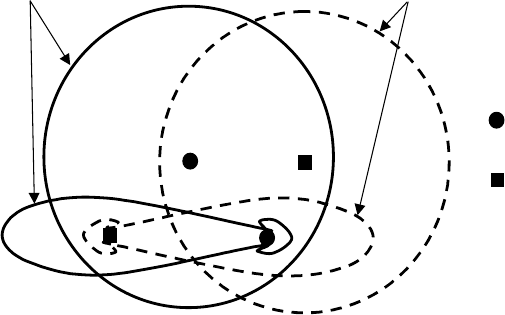
Figure 7.2 illustrates the difference in the operation of transmitters and receivers that use
directional antennas. This illustration plots the location of two pairs of transmitters and
receivers and shows the effect of their antennas. Because T1 and R1 have omni-directional
antennas, they transmit and receive in all directions equally. But since T2 and R2 use
directional antennas they transmit and receive with increased gain in one direction. We note
that although R1 receives in the direction of T2, it will still receive T1’s signal since T2 does
not radiate in the direction of R1. This is so regardless of whether R2 uses a directional
antenna. Similarly, R2 can receive T2’s transmission even though it is in range of T1 since
its antenna gain is so much greater in the direction of T2. This is so regardless of whether T2
uses a directional antenna. It is possible to increase the density of transmitter-receiver pairs
in a geographic area by increasing the number of radios using directional antennas and by
increasing the directionality of the antennas.
Transmitter
Receiver
Relative gain of
the receiving
antenna
Range of
transmission
R1
R2
T1
T2
Figure 7-2. Comparison of omni-directional and directional antenna coverage.
7.4.2 Networking
Networking increases spatial reuse by enabling communicating sources to send a
communication to a distant destination without having to transmit the communication the full
range of their separation. This is accomplished by relaying the communication through
nodes of the network. Since nodes only transmit a short distance, they can use low power in
their transmission and allow other nodes to use the same channel simultaneously. This also
makes it more difficult to detect and intercept those nodes that do communicate.
We note that there is no requirement that networks be formed solely with nodes that use
wireless links. Being able to move traffic across links that do not use the radio spectrum
7-9
(i.e., wired links or optical links) is another method of increasing the availability of RF
spectrum to more services. Placing such links within a network can greatly increase the
capacity of the network and thus the benefit of the RF spectrum. Wireless networks may be
one of two types, centrally controlled or ad hoc.
7.4.2.1 Centrally Controlled Wireless Networks
Centrally controlled wireless networks consist of relatively smart stations called “access
points” or “base stations” that are physically connected to each other and other mobile, and
relatively dumb stations that send and receive all of their traffic through these access points.
The mobile stations communicate with the closest access point. They have no further
understanding of the network topology. The access points work cooperatively to route
communications between sources and destinations. The coverage of these networks is
dependent on the locations of the access points. Examples of this type of network are
cellular telephone systems, the Army’s Mobile Subscriber Equipment (MSE), and the
trunked radio systems that are found on military installations.
Centrally controlled networks have many advantages over ad hoc networks. The smart
access points can easily manage quality of service. Since the mobile stations need only
communicate with access points and are not involved with routing traffic there is much less
overhead; so scaling of the network is not an issue. However, these networks also have
disadvantages. Mobile stations cannot communicate unless they associate with access points
and these access points can become bottlenecks and central points of failure. Centrally-
controlled networks are quite vulnerable to hostile acts in military environments.
7.4.2.2 Ad Hoc Networking
Mobile ad hoc networks (MANET), also referred to as mesh networks, consist of mobile
stations that work cooperatively to form a network. Mobile stations in these networks
discover each other and cooperate to form a network topology. There is no requirement for a
pre-existing infrastructure. The creation of these networks is quite complex and remains a
very active area of research with no clearly defined best approach. Conceptually, they
provide the best networking paradigm for the military and are the objective of several
ongoing programs. There is no single point of failure and no limit to the area over which
they may operate. The current program to develop the Wideband Networking Waveform
(WNW) for the JTRS radio is an effort to build a terminal that will provide this type of
capability for the military. The advantages of MANETs are that they are rapidly deployable
and require no fixed infrastructure. The disadvantages of MANETs are that they don’t
perform uniformly, they are sensitive to use, and they do not scale well with network size.
7-10
7.4.3 Spread Spectrum Communications
Spread spectrum communications, as the name implies, spread the signals of
communication across a wide frequency band. There are three primary methods: frequency
hopping, time hopping, and direct sequence. Of these, frequency hopping is the most
obvious. Radios, rather than transmitting continuously using one carrier on a regular basis,
hop to different frequencies to send portions of the message. Multiple transmitters can then
use the same spectrum by using and hopping to different frequencies. To enable the use of
multiple channels requires the radios in the band to follow hop sequences that are non-
interfering. In this subsection, however, we want to explore more closely the other forms of
spread spectrum. The difference in these methods is that multiple signal will use the exact
same spectrum simultaneously. Below, we describe how a signal is spread in spectrum and
demonstrate that, once spread, it appears as noise. We then describe the differences between
direct sequence (DS) and the time hopping approach of UWB.
7.4.3.1 More Basics of Signals in the Spectrum
In Figure 1-2 we illustrated the spectrum of a square wave. We saw that the spectrum of
the square wave extended continuously from its fundamental frequency, the frequency of the
square wave, f, with each spike occurring at odd multiples of the fundamental frequency, (i.e.
3f, 5f, 7f, …). Certainly, as the frequency of a square wave increases, so too will the breadth
at which its spectrum is spread. A second method of spreading spectrum is to reduce the
width of the signal pulse. In Figure 7-3 we illustrate the correlation of frequency and pulse
width of the modulating signal to how the transmitted signal is spread in spectrum. The
frequency of the pulses determines the specific frequency components used in the spectrum
and the width of the pulses determine the amplitude of those components. Converting
signals to shorter pulses or to a series of fast pulses will spread their spectrum. When these
pulse trains modulate a carrier signal, the spectrum extends in both directions about the
carrier. The more a signal is spread in the spectrum, the lower the perceived signal strength
in the spectrum. If spread sufficiently, the signal can hide behind the background noise.
7-11
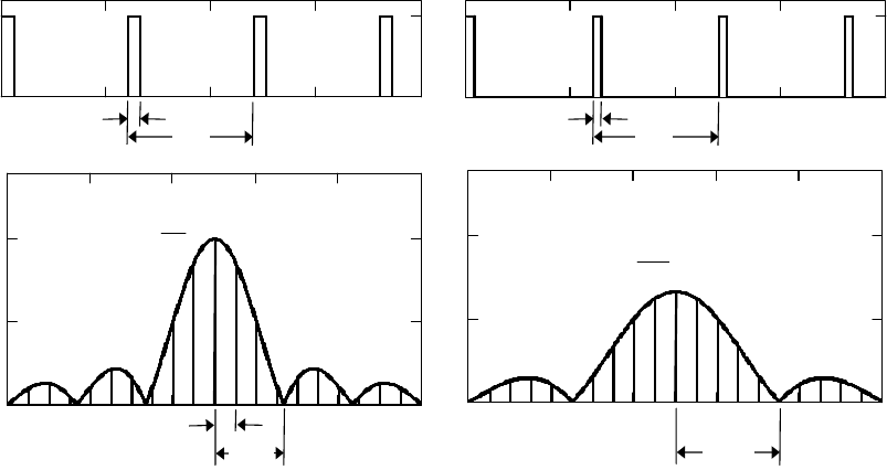
T
τ
T
-1
τ
-1
T
τ
2
τ
2
-1
A
A
τA
T
2
τ A
T
f
c
f
c
Figure 7-3. Effect of pulse width on spectral content. The shorter pulse width τ
2
spreads the spectrum further than the τ pulse width.
7.4.3.2 Direct Sequence Spread Spectrum
The concept of direct sequence spread spectrum (DSSS) is illustrated in Figure 7-4. A
low rate data signal (Figure 7-4a) is mixed with what is called a chip sequence, a.k.a. a
pseudo- noise (PN) sequence, (Figure 7-4b). The output of this operation is a new signal
(Figure 7.4c). Since it involves a faster changing signal, its content is spread across the
spectrum. At the receiving end, the arriving signal is mixed with the same PN sequence and
the intelligence is extracted (Figure 7-4d). If there is an interfering signal present in the
received spectrum, that interfering signal will be spread by the PN sequence at the receiver.
As a result, signals can be detected in the presence of other signals (see Figure 7-5).
Additionally, several DSSS signals can be sent and received at the same time as long as their
spreading sequences are different. This is the concept of CDMA. CDMA works best when
the codes used are orthogonal. This means that when the different PN sequences are
multiplied with each other their product is zero. Highly accurate timing of the arrival of
signals at destinations is required for orthogonal CDMA to work.
7-12
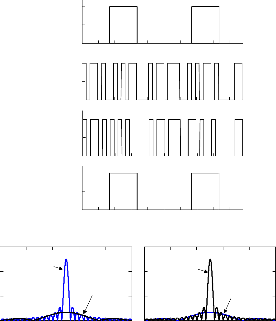
Signal
Pseudo-noise
sequence
Transmitted
signal
Recovered
signal
s(t)
pn(t)
a(t) = s(t) ⊕ pn(t)
b(t) = a(t) ⊕ pn(t)
a.
b.
c.
d.
Figure 7-4. Example of Direct Sequence Spread Spectrum (DSSS)
Jamming
signal
Desired
DSSS signal
Desired
signal after
despreading
Jamming signal
is spread
a. Received signals prior to despreading
b. Received signals after despreading
Figure 7-5. Anti-jam characteristics of DSSS
7-13
7.4.3.3 Ultra Wideband
The concept of UWB is to send information in very short pulses that have a very wide
bandwidth because they are short. Receivers detect these pulses, as opposed to seeing noise,
by knowing when to look for them. If several pulses are observed when they are expected to
be present, then the signal is detected to be present. (See Section 1.2.2.)
It is possible to directly transmit very narrow electromagnetic impulses without
modulating them onto a sine wave. These impulses occupy spectrum from zero Hz up to a
frequency that is approximately the reciprocal of the pulse width. This constitutes one form
of UWB technology. A radar that operates on this principle can resolve objects whose
dimensions are similar to the width of the pulse. Such a system transmits energy over a wide
band of spectrum that has been allocated to many other services, and has the potential to
interfere with those services. However, these radars can penetrate obstacles and provide
radio detection capabilities that are not possible in other bands.
There is another form of UWB, where the pulses modulate a sine wave with a bandwidth
that is a substantial fraction of the carrier frequency. If the carrier frequency is appropriately
selected, such a system could operate in a region of the spectrum that is not much used by
other services. However, the services provided by the UWB signal are frequency dependent.
For example, obstacle-penetrating radar would not be possible at higher frequencies.
7.4.4 Signal Polarization
Just as light has polarization so, too, do electromagnetic RF waves. The polarization of
electromagnetic RF waves is determined by antenna geometry. For example a long-wire
vertical antenna will have linear vertical polarization, while a horizontal long wire antenna
will have linear horizontal polarization. Reciprocally, best reception occurs when the
receiving antenna’s geometry matches the polarization of the electromagnetic waves. Thus,
polarization can be used to separate signals using the same frequency bands in the same
location by designing antennas to transmit and receive the signals at distinguishably different
polarization.
7.4.5 Smart Antennas
As illustrated in Figure 1-11, signals are detected at an antenna when their fields cross the
antenna. If there are multiple antennas that are physically separated from each other, each
will receive the signal at a different time. This difference in the arrival of signals at each
element of an array of antennas can be used to isolate multiple signals simultaneously. In
this subsection, we describe the basic physics that enable this technology to work.
7-14
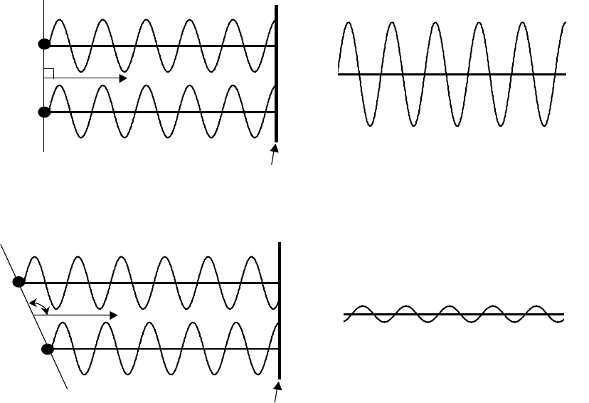
Observation point
+ =
Observation point
+ =
a. Direction of propagation with in-phase arrival of signals
b. Direction of propagation with out-of-phase arrival of signals
Figure 7-6. An example of constructive and destructive interference from two signals
that are transmitted in phase from two adjacent antennas based on direction of
propagation.
7.4.5.1 Constructive and Destructive Interference
When two identical signals are transmitted from multiple antenna elements they will
create a wavefront that will propagate in different directions. At a distant point from these
source antennas, an antenna will receive both signals, but since they propagate different
distances, the relative phase of these signals may differ. If the phases line up, then there is
constructive interference and the signals reinforce each other; see Figure 7-6a. If the phases
do not line-up, then there is destructive interference and no signal may be detected, see
Figure 7-6b.
7-15
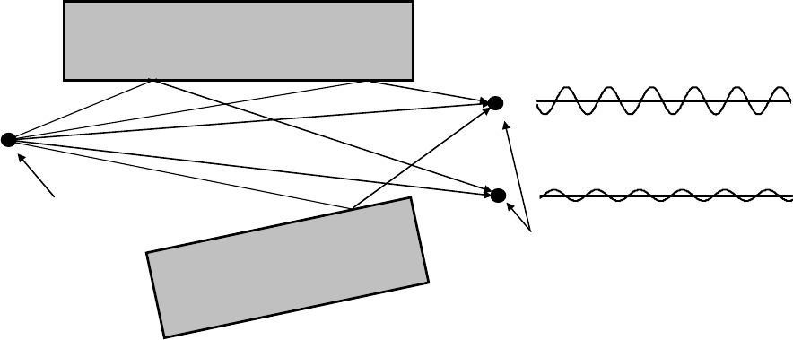
7.4.5.2 Beamforming
It is possible to select a direction that signals from an array of antennas can
constructively interfere. This direction is affected by selecting the phases and amplitudes of
signals at each of a number of arrayed antenna elements. The direction at which signals
optimally reinforce each other is called the main beam of an antenna. Similarly, it is possible
to excite the antenna elements in a way that causes signals to destructively interfere in a
desired direction. A direction where the signals of an antenna array completely cancel each
other is called a null. Simple beam steering can be accomplished by shifting the phases of
signals to antenna elements based on their physical separation from each other.
Signals detected by each
antenna element
Signal source
Receiving
antennas
Figure 7-7. Differences in received signals caused by multipath arrival of signals at the
receiving antennas
7.4.5.3 Spatial Signatures
In practice, signals from the same source will arrive at antennas from many different
directions. See Figure 7.7. The additional signals occur because of reflections that may
occur off the earth and man-made structures. If there is some prior knowledge about an
arriving signal, multiple element antennas can be optimized to receive signals from a specific
source; Transmissions are normally preceded by a training sequence, and then the
destination applies an algorithm to calculate factors that multiply each antenna’s received
signal, prior to adding them, that causes the sum of these signals to be most similar to the
known training signal. The specific way that a signal arrives at the different antenna
elements is referred to as its spatial signature. Antennas and propagation characteristics are
usually reciprocal. If a receiving antenna can learn the spatial signature, it can then use it to
optimize its return signal to the source. Since there is a rich spatial diversity in how signals
7-16
can arrive, this diversity can be used by antennas to enable them to detect the transmission of
a single source even though the signals of multiple sources arrive at the antenna. It also
enables these antennas to receive multiple signals simultaneously that only differ in their
spatial signature. These antennas can also be used to transmit different signals to multiple
destinations simultaneously. Antennas that can do this are referred to as smart antennas.
The effectiveness of these antennas depends on the geometry and number of elements the
antennas have.
7.5 Dynamic Spectrum Management
Dynamic spectrum management technologies enable spectrum users to identify available
spectrum and then to use that spectrum when they need it. Radios that can perform this
function are referred to as “smart radios.” We consider two different technologies. In the
first, radios check to see what spectrum is currently being used and, in an opportunistic way,
use spectrum that is available (spectrum mining). In the second, radios are aware of the
frequency bands they may use and then work cooperatively to share that spectrum for its
maximum use (dynamic channel assignment). Due to the cooperative nature of these
solutions they would likely be implemented together with networking technologies.
7.5.1 Spectrum Mining
In spectrum mining, radios look for spectrum that is not being used and then use it. The
DSP technologies that enable identification of frequency content (See Section 7.3.1) are also
the enabling technologies in this approach. A radio can sample a band of frequencies and
measure the energy that is present in that spectrum to find those portions that are not being
used. The more complicated part of implementing this technology is knowing which
frequency bands the radio may use and then coordinating its use with the intended
receiver(s). If the spectrum is available in a secondary status, its use must be coordinated to
ensure that it does not violate the terms of its use. These terms of use would include
regulatory constraints to ensure primary spectrum users retain their precedence. How to
define these terms and ensure compliance is still an open issue, as is the regulatory priority in
blocks of spectrum encumbered by other opportunistic users such as WiFi or other
unlicensed devices. In addition, the regulatory status of radios employing a spectrum mining
technique would need to be defined such that their use could be regulated in some manner (or
assigned to unlicensed spectrum only under Annex K of the NTIA manual or Part 15 of the
FCC’s rules). From a technical perspective, an additional problem is coordinating a
transmitter’s intent to use a particular piece of spectrum with the intended receiver so that the
receiver can tune to the correct channel. Because of the knowledge and coordination
required, this technology is best implemented with a network. Radios that have the ability to
intelligently detect whether a particular segment of radio spectrum is being used and use it as
described above are called cognitive radios.
7-17
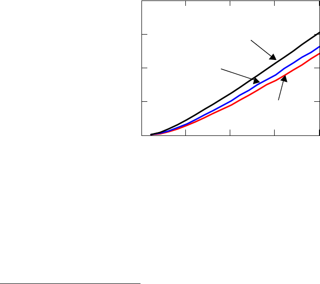
7.5.2 Dynamic Channel Assignment
Multiple channels may be available for radios to use to communicate. This plurality of
channels can be exploited in several ways. In the first, channels can be assigned on a first-
come first-serve basis such as used in cellular phone systems. The dynamic assignment of
channels to calls enables the channels to be used most efficiently. This method of channel
assignment is a form of statistical multiplexing. In systems where most communications are
randomly-occurring point-to-point communications, the concern is probability of blocking—
the probability that a terminal will ask to use a channel and none will be available. In
systems that dynamically assign channels in this manner, the quantity of traffic that the
multiple channel system can support with the same probability of blocking increases
dramatically. We illustrate this improvement in Figure 7-8. Each of the plots in this figure
corresponds to a different blocking probability, p
B
. For the case of p
B
= 0.01, a system that
shares 20 channels can support 1200 times the load supported by a 1 channel system
operating with this same blocking probability.
0 5 10 15 20
0
5
10
15
20
Number of Channels
Erlangs
p
B
= 0.01
p
B
= 0.02
p
B
= 0.05
Figure 7-8. Graph of the Erlang C formula showing the benefit of statistically
multiplexing channels to support randomly arriving traffic
11
The second method of dynamic channel assignment is reassigning the same channel to
different groups of nodes based on their current disposition. In some ways this was done by
the original cellular phone system, which reused frequencies in cells that were separated
11
An Erlang is the maximum capacity of a channel. So 1 channel has 1 Erlang of capacity and 20 channels
have 20 Erlangs of capacity. The Erlang C formula, which generates this graph, correlates the effective use
of the channels with a probability of being blocked assuming Poisson arrival and exponential service times
for the traffic.
7-18
from each other. However in the cellular phone system this assignment was not dynamic. A
dynamic assignment is accomplished through the ganging of multiple radios where one radio
is on a network. Each user has multiple radios where one is assigned to operate in a network
and the others are assigned logically to multicast groups and are not assigned channels.
Distributed algorithms, implemented in the network, assign the channels. Groups of radios
that want to form a multicast group can be assigned one of the channels available to the
network for one of their non-network radios to use. The network would know which
channels were being used and would assign a channel to the multicast group that was not
being used by any other transmitters in the same vicinity. Transmission characteristics such
as transmit power may also be specified. Thus the network can control the geographic extent
of the spectrum’s use. The network identifies the locations of the nodes of the multicast
group and reassigns the same channel to another multicast group if it is sufficiently separated
in distance from this group. When the second radio is an SDR, it may also be possible to
choose the waveform that is most suitable for the multicast group. This method of dynamic
assignment can greatly reduce the number of channels that are required to support multiple
multicast groups. Through this type of technique, for example, the voice nets of several
different platoons can use the same channel so long as they are separated from each other.
The network can also change the channels of these multicast groups if they maneuver within
range of each other. The assignment and changing of channels can be made totally
transparent to users.
Figure 7-9 illustrates a notional layout of a formation. Each circle represents a member
of the organization. All have a radio on the common ad hoc networking channel. The
numbers adjacent to these circles are the multicast groups that each member subscribes. If a
member has one number it has two radios, one is a member of the common ad hoc network
and the second is available for the multicast group. If a member has two numbers it is a
member of two multicast groups and has three radios total. The dashed lines circumscribe
nodes that belong to the same multicast groups. The number of the multicast group is a
logical association; it does not map directly to a radio channel. Rather, it only indicates that
all nodes that subscribe to the same group should be on the same channel. The network
assigns the channel. Through this approach, multicast groups that are separated from each
other, for example 5 and 9, could be assigned the same channel to use. The spectrum mining
technology would complement this process by verifying the availability of spectrum for
multicast groups to use.
7-19

1
1, 2
3, 4
2, 4 1, 3
2, 5
2, 6
2,7
3, 8
3, 9
5
5
5
6
6
6
7
7
7
8
8
8
9
9
9
Figure 7-9. A notional layout of members of a military formation showing subscription
to multicast groups
7.6 Alternative Perspectives on Efficient Spectrum Management
There are three models that were proposed by the FCC Spectrum Policy Task Force [23]
in November 2002 for the management of spectrum: the “command-and-control” model, the
“exclusive use” model, and the “commons” model.
The command-and-control model is the traditional process of spectrum management
where the regulatory authority assigns frequencies to spectrum users for specific uses, which
are constrained by rules that limit the characteristics of transmissions. The effectiveness of
the command-and-control model is improved by those technologies that seek spectrum and
information efficiency and by spatial reuse technologies that can be regulated such as the use
of directional antennas.
The exclusive use model gives the licensee the rights to the spectrum within a defined
geographic area and then that licensee manages that spectrum for its optimal use, transferring
the right to use it, if that is appropriate. The mobile phone system is an example of the
exclusive rights model. All of the technologies discussed in this section can be exploited in a
band of frequencies that are available for exclusive use.
The commons model allows significant numbers of unlicensed users to share the
spectrum where usage is governed by technical standards or protocols. There is no right to
protection from interference. The wireless applications authorized for parts of the ISM band,
7-20

where there are no licensed spectrum users, demonstrate this concept. Wireless local area
networks (LANs), Bluetooth devices, cordless phones, and microwave ovens all share the
same frequencies. The spatial reuse technologies that use diversity to allow signals to
coexist in the same space support efficiency in this model. Since transmission power is
limited, networking technologies are exploited to extend the effective range of
communications systems and the type of services they can provide.
The general non-government view is that the exclusive use and commons models will
provide a more efficient management of spectrum, since they decentralize control, making
them more responsive to user needs. In the case of the exclusive use model, licensees can
continuously optimize the assignment of spectrum for best use as defined by the licensee. In
the commons model, users seek to find the best technologies and implementations that
provide the services they need. Although non-government interests often question whether
the government uses spectrum efficiently, the DoD can point to the fact that the exclusive use
model most closely represent how it manages spectrum. As described in Section 6,
frequencies are pooled geographically and provided to users by area coordinators. This
pooling occurs both nationally and internationally. Thus, the DoD, out of necessity, is a
leader in the development and implementation of technologies that are well suited for
dynamic and flexible frequency management
12
The DoD is at the forefront of developing standards, protocols, and techniques that would
permit flexibility in spectrum use, including the use of the commons model. However, use of
this model for shared government and non-government bands requires further examination
from a technical, regulatory, and political perspective before it should be seriously
considered. Initial use of this model would likely be in dedicated spectrum blocks. More
widespread use may become feasible as technologies and techniques mature and regulatory
issues are addressed. Such improvements may occur as the DoD fields systems that enable
the real time management of spectrum.
7.7 Summary
New communications technologies are providing opportunities to obtain more services
and capacity from spectrum. These technologies improve spectrum use and management in
five general ways:
12
This statement should not be construed to mean that DoD has established any band as a commons band,
nor, that it currently supports the use of the commons model for the spectrum DoD shares with non-federal
users. Many technical, regulatory, and policy issues remain to make the commons model work in a manner
that will not compromise DoD’s mission capability. The point is that the DoD is a leader in the
development of the technologies that are used in this approach.
7-21

1. Information efficient technologies improve spectrum use by optimizing the quantity of
information that is sent. The goal of information efficient technologies is to reduce the
quantity of bits that must be used to represent information.
2. Spectrum efficient technologies try to reduce the quantity of spectrum needed to send bits
at a specified rate.
3. Digital signal processing technologies change the way signals are processed in
transmitters and receivers. They enable new ways to modulate and detect signals and
make transceivers more flexible. Radio capabilities can be defined in software. DSP has
done for communications transceivers what microprocessors did for the adding machine.
In addition to being able to perform the adding function, computers can do a whole lot
more through software. Similarly, software-defined radios will enable transceivers to do
a whole lot more, many of the capabilities may not as yet have been discovered. At the
very least, they enable transceivers to be continuously upgraded to employ the most
spectrum efficient technologies.
4. Spatial reuse technologies attempt to increase the number of users that may use the same
spectrum simultaneously. It achieves this goal by either reducing the spatial footprint
over which transmissions can be heard, or by using diversity to enable multiple
transmitters to use the same spectrum in the same space at the same time.
5. Dynamic spectrum management enables the management of spectrum in real time.
These systems first identify what spectrum is available and then assign it to users for the
best benefit. These systems may be directed as to what spectrum they might use or may
search for available spectrum and then use it on an opportunistic basis.
13
None of these technologies is the clear winner in providing the best use of spectrum.
Choosing any particular metric to measure efficient use of spectrum will prefer one
technology over another. Military users of spectrum seek not only the most efficient way to
send bits but also the most reliable way. Metrics that seek spectrum efficiency, i.e.,
bits/seconds/hertz, may favor technologies that are not sufficiently reliable.
Additionally, the model used to manage spectrum may limit or enable the exploitation of
these technologies. There are three management models that have been proposed: command-
and-control, exclusive use, and commons models. The command-and-control model tends to
favor information and spectrum efficient technologies and discourage technologies that
require wider bands of spectrum. The command-and-control model best describes how
management organizations, e.g., ITU, NTIA, and FCC, manage spectrum. While many
believe the exclusive use and commons models provide the most efficient way to manage
13
Subject to a regulatory regime that would support such use and definition of certain access rights for
opportunistic uses of encumbered spectrum.
7-22
spectrum for its exploitation because they enable the use of all of the technologies described
herein, there are significant regulatory and technical issues associated in implementing these
models, the implications of which have barely begun. It is quite possible the use of these
models may be relegated to dedicated spectrum blocks for the foreseeable future. Although
the DoD is assigned frequencies, they are then pooled and managed by area and by mission.
In effect, the DoD often uses the exclusive use model to manage spectrum use.
Improvements in DoD use of spectrum will follow from the further development of the
technologies we have described and addressing associated regulatory issues.
7-23
7-24
Section 8
Real World Constraints in Spectrum Management
Throughout the century the perception has always been that there is not enough spectrum
available. However, technology continues to resolve this problem by making more spectrum
usable. For example, the upper limit of the spectrum managed by the ITU-R has changed
throughout the years:
Pre 1947 = 200 MHz
1947 = 10.5 GHz
1959 = 40 GHz
1971 = 275 GHz.
300 GHz is at the beginning of the spectrum where electromagnetic radiation starts to
become light; this is the practical limit of radio frequencies. Further increases in radio
spectrum capacity now require us to use the spectrum we have more efficiently. As
described in Section 7, numerous technologies are available to make this possible. However,
the best way to transition is not clear. Ninety years of regulated use and allocations has
created a number of issues that must be considered. The purpose of this section is to
delineate these issues. To do this, we identify four: legacy allocations, legacy equipment, the
desirable features of future spectrum assignments, and transition issues. We follow with a
discussion of how the most recent regulatory actions addressed these challenges—at times
contrary to DoD’s best interests—by providing more spectrum to commercial users.
Specifically, they reallocated federal exclusive use bands for non-federal use.
8.1 Legacy Allocations
The allocation of spectrum has its roots in the order that technology and services were
developed. Generally, the lower the frequency used, the earlier the service was allocated.
There are two issues associated with this sort of development. First, the older technologies
that enabled the services tend to be less efficient. Second, frequencies may not be allocated
in the best way for the services. As described in Section 1, signals operating at different
frequencies perform in different ways. For example, it would be a poor choice to put
emergency and police bands in a frequency band that could not penetrate buildings.
Spectrum management is as much about human nature as it is about science.
Considering the complexity of getting assignments and the role registry plays in a user’s
right to use a frequency, there is great incentive for users that have assignments to hold onto
them even if they are not using them.
8-1
8.2 Legacy Equipment
Improving the use of existing allocations requires the improvement of the equipment.
This most normally requires replacing it. Thus, there is an expense associated with any
changes in how spectrum is allocated. The palatability of any reallocation plan will be
contingent on the number of users of the old allocations. Changing spectrum allocations will
always create an economic loss to someone, and care must be taken to prevent compromising
national security and public safety during the transition.
8.3 Desirable Features of Spectrum Assignments
As one would expect, the new services that are projected for spectrum prefer contiguous
bands of spectrum that are wholly allocated for the exclusive use of the service provider. An
additional consideration is that specific spectrum characteristics that are desired for the
service are frequency dependent.
Anticipated commercial and military uses of spectrum involve supporting multiple users
simultaneously with the same spectrum. The discussions of Section 1 and Section 7
postulate that providing a service that supports multiple users is best accomplished through
assigning contiguous bands of spectrum rather than assigning multiple small slices dispersed
across different bands. Some reasons for this preference are
1. Circuit performance is dependent on frequency.
2. Antenna performance is dependent on frequency.
3. Propagation effects are dependent on frequency.
4. Some advance technologies, such as spread spectrum, require wide bands of
spectrum.
Items 1 to 3 indicate that radios using multiple channels should operate within the same
relative frequencies, or else the transceivers will perform differently for each channel. Thus,
radios are designed and optimized for a specific range of frequencies. Splitting spectrum up
decreases its utility and increases the cost of the devices that are designed to use it.
Referring back to Section 1, we also note that the potential uses of spectrum are
frequency dependent. Any old slice of spectrum will not do; most users want frequency
assignments in the most desirable bands—generally below 3 GHz, in what is commonly
called the “beachfront” portion of the spectrum. The band of frequencies from which an
assignment is given must be selected to provide the propagation characteristics that are
required for the service. For example, a microwave oven can only work in a certain band of
frequencies. Water molecules are especially effective in absorbing energy at about 2.4 GHz
(see Figure 1-22), so most ovens operate near this frequency.
8-2
8.4 Transition Issues
Any decision that directs the reallocation of spectrum or the improvement of the
technologies using it requires a transition. Transitions rarely occur instantaneously. The
natural tendency is for service providers, users, and equipment manufacturers to delay
transitioning until the last moment. This is being played out in the current transition to
digital television. In cases where services are moved from one slice of spectrum to another,
transitions may require providing the same service in two places in the spectrum
simultaneously for the transition period. As equipment is replaced there is the possibility
that incompatible systems will degrade the capability of the service. In cases where
transitions occur in the same band this incompatibility may prevent using the different
equipment simultaneously. These types of problems are especially acute for services that
support public safety and other critical services. Fundamentally important, however, is
maintaining an awareness that technology alone is never the only consideration in spectrum
management. Political issues, regulatory impacts, costs, and legal implications must also be
considered.
8.5 Changing Spectrum Use
Any plan to change the way a particular block of spectrum is used will involve some
level of resistance for the reasons described above. Whether or not technology can overcome
the perceived shortage of spectrum is dependent on some changes in spectrum management.
Policy makers must consider whether projected changes are trying to achieve the best use of
spectrum or simply trying to seize spectrum from those users that will provide the least
resistance or are the easiest to move. If the latter is the motivation, changes are likely to
exacerbate the perceived problem of spectrum shortage. The most recent conversion of
federal exclusive use spectrum to commercial uses has had both an economic and operational
impact on the previous users of that spectrum, most notably, as described in Section 4, on the
DoD.
The historical methods and bureaucracy of spectrum management will tend to favor
spectrum use changes that seek to eliminate inefficient use so that it may be reassigned. This
is not undesirable, but the better solution to any optimization problem requires consideration
of all available resources and desired outcomes in the optimization. Policy makers should be
suspicious of change proposals that focus on eliminating perceived inefficient users rather
than on optimum use of spectrum. Such approaches are opportunistic and are not likely to
achieve the best use of spectrum.
The process of reviewing the use of spectrum and changing the rules to improve the
appropriateness or efficiency of its use is referred to as spectrum refarming. Currently, the
predominant refarming method in the U.S. is “narrow-banding,” where current channels are
being divided into narrower bands.
8-3
8.6 Conclusion
The legacy of over 90 years of spectrum management and the entrenchment of various
users of spectrum create an inertia that works against exploiting technology to improve
spectrum use. Exploiting technology to its fullest will require some changes in the way
spectrum is managed. Unless proper attention is given to optimizing the use of spectrum—
balanced with political, legal, and regulatory consideration—change is unlikely to occur in
the foreseeable future. Political interests will continue to encourage the seizing of federal
allocations. The most recent reallocations of federal exclusive use spectrum have affected
and will continue to affect the ability of the DoD to execute its mission. As pressures
continue to mount for federal users to give-up spectrum, policy makers should be aware that
the modernization of military forces is based on the ability to exploit the communications,
surveillance, and navigation capabilities that are made possible by the use of spectrum. The
evolution of military forces, even with technology improvements, will require more access to
spectrum, not less.
8-4
List of References
1. ITU, Radio Regulations, International Telecommunication Electronic Publishing Service,
2001.
2. DoC NTIA, Manual of Regulations and Procedures for Federal Radio Management,
September 2001.
3. FCC Rules and Regulations (CFR Title 47, Telecommunications, Part 95, Personal Radio
Services)
4. http/:www.itu.int/aboutitu/structure.
5. http/:www.itu.int/aboutitu/overview.
6. http/:www.itu.int/ITU-R.
7. http:/www.state.gov/e/eb/
8. http:/www.state.gov/e/eb/cip/
9. http:/www.state.gov/e/eb/cip/c621.htm
10. http:/www.fcc.gov/fccorgchart.html.
11. http:/www.disa.mil/ops/spectrum.html
12. Defense Spectrum Office Mission and Functions, 2003.
13. Working Group 7 of the Spectrum Planning Subcommittee, Federal Long-Range
Spectrum Plan, NTIA, September 2000.
14. OPNAVINST 2400.20E, Navy Management of the Radio Frequency Spectrum, 19
January 2002.
15. AFMAN 33-120, RadioFrequency (RF) Spectrum Management, 3 April 2002.
16. DoDD 3222.3, Department of Defense Electromagnetic Compatibility Program, 20
August 1990.
17. DoDD 4650.1, “Electromagnetic Spectrum – Management and Use,” XX 2004.
18. DoD Reform Initiative Directive #31 – Realignment of DoD Spectrum Management
Responsibilities.
19. DoDD 5100.35, “Military Communications-Electronics Board (MCEB),” 10 March
1998.
20. Joint Publication 1-02, Department of Defense Dictionary of Military and Associated
Terms, 12 April 2001 as Amended Through 5 September 2003
RE-1
21. DoD Memorandum, “Implementation Guidance on Restructuring Defense Intelligence –
Related Matters” 8 May 2003.
22. CJCSI 3320.01A Electromagnetic Spectrum Use in Joint Military Operations, 30
September 2002.
23. CJCSI 3320.02B, Joint Spectrum Interference Resolution (JSIR) , 12 September 2003.
24. CJCSI 3320.03, Joint Communications Electronics Operation Instructions, 23
September 2003.
25. CJCSM 3320.01A, Joint Operations in the Electromagnetic Battle Space, 27 September
2002.
26. CJCSM 3320.02, Joint Spectrum Interference Resolution (JSIR) Procedures, 8
November 2002.
27. ACP 190(B) Guide to Spectrum Management in Military Operations, May 2003.
28. ACP 190 US Supp-1(C), Guide to Frequency Planning, April 1991.
29. AR 5-12, Army Management of the Electromagnetic Spectrum, 1 October 1997.
30. AFI 33-118, Radio Frequency (RF) Spectrum Management, 3 April 2002.
31. The Communications Act of 1934
32. MCO 2400.2, Marine Corps Management of the Radio Frequency Spectrum, 16 June
1989.
33. Defense Science Board Task Force on DoD Frequency Spectrum Issues, “Coping with
Change: Managing RF Spectrum to Meet DoD Needs,” November 2000.
34. Defense Science Board Task Force on Wideband Radio Frequency Modulation,
“Wideband Radio Frequency Modulation, Dynamic Access to Mobile Information
Networks,” July 2003.
35. FCC “Spectrum Policy Task Force Report” ET Docket No. 02-135, November 2002.
36. Shea, R.M (BG), “Concerning Managing Radio Frequency Spectrum: Military Readiness
and National Security,” Statement before the Subcommittee on National Security,
Veterans Affairs, and International Relations on 23 April 2002.
http:/www.house.gov/reform/ns/statements_witness/shea_april23.html.
37. http:/www.jsc.mil/AcqSup/Gen_spec_policy&info.asp
38.
MCEB PUB 1, Military Communications-Electronics Board Organization, Mission, and
Functions Manual, 1 March 2002.
RE-2
39. MCEB PUB 2, Military Communications-Electronics Board Organization,
Administrative Procedures Manual, 31 May 2002.
40. Howeth, L.S. History of Communications-Electronics in the United States Navy, United
States, Government Printing Office, Washington: 1963. Library of Congress Catalogue
Number: 64-62870.
41. Porter, W.A., “Administrative Aspects of Telecommunications,” IEEE Transactions on
Communications, Vol. 02, Nov 1954, pp. 14 - 17.
42. de Wolf, F.C. “The ITU and Global Communications,” IEEE Transactions on
Communications, Vol. 02, Nov 1954, pp. 18 - 21.
43. Miles, P.D. “International Radio Frequency Management,” IEEE Transactions on
Communications, Vol. 02, Nov 1954, pp. 22 - 25.
44. FCC, “History of Wire and Broadcast Communication,”
http:/www.fcc.gov/cgb/evol.html, May 1993.
45. FCC, “Millimeter Wave Propagation: Spectrum Management Implications,” FCC
Bulletin Number 70, July 1997.
46. IEEE Std 100-192, The New IEEE Standard Dictionary of Electrical and Electronics
Terms, IEEE, 1993.
47. IEEE Std 521
TM
-2002, IEEE Standard Letter Designations for Radar-Frequency Bands,
IEEE, 8 January 2003.
48. http://www.ieeeuse.org/forum/postions/cognitive radio.html, “IEEE USA Position on
Improving Spectrum Usage Through Cognitive Radio Technology.”
49. Kennard, W.E. “Connecting the Globe: A Regulator’s Guide to Building a Global
Information Community,” FCC, June 1999.
50. Maher, R. and Wentland, F., “Spectrum Management Structure and Regulations in the
U.S. – Do we Need to Change in the Twenty First Century,” IEEE Symposium on
Electromagnetic Compatibility, 1990 pp. 380-385.
51. Collin, R.E. Antennas and Radiowave Propagation, McGraw Hill Inc., 1985.
52. Allen, E.W., “The Organization and Functions of the CCIR,” IEEE Transactions on
Communications, Vol. 02, Nov 1954, pp. 26 - 29.
53. MacQuivey, D.R., “Improving Frequency Management to Facilitate Global
Communications,” IEEE Transactions on Communications, Vol. 02, Nov 1954, pp. 30 -
34.
RE-3
54. Smith, E.K. and Kirby, R.C. “The International Radio Consultative Committee (CCIR):
Part 1, IEEE Communications Magazine, Vol. 12, pp. 11 - 18, Jul 1974.
55. Smith, E.K. and Kirby, R.C. “The International Radio Consultative Committee (CCIR):
Part 2, IEEE Communications Magazine, Vol. 12, pp. 12 - 19, Sep 1974.
56. Messere, F. The Federal Communications Commission: An Historical Overview,
http:/www.oswego.edu/~messere, 1996.
57. Merrill, A. B. and Weiskopf, M., “Critical Issues in Spectrum Management for Defense
Space Systems,” http:/www.aero.org/publications/crosslink/winter2002/02.html.
58. I. Brown, A. Kavetsky, M.J. Riccio, and M. Weiskopf, “Spectrum Management and
International Filing: A Program Management Perspective on Process and Recent
Developments,” IEEE Aerospace Conference 2001, Vol. 3, 2001, pp. 3/1261-3/1269.
RE-4

Appendix A
DoD Spectrum Use
14
Band MHz Military Usage Planned Usage Notes
30-54 Military LMR. This band is used for tactical and
training operations by U.S. military combat net
radio operations that provide command and control
for combat, and combat service support units.
Frequencies also used for air-to-ground
communications for military close air support
requirements as well as some other tactical air-
ground and air-air communications. This band is
broken down into 21 subbands that have different
allocations. Some subbands are not allocated to
Government use. Those subbands are used by the
military services for tactical and training
operations on a non-interference basis.
No changes are planned.
Use expected to
continue.
Multiple
subbands,
some
Government
primary, in
others
military
operates NIB
74.6-74.8 Military LMR. Usage range from administrative
land mobile nets to ground communications for
military aircraft crews
No changes are planned.
Use expected to
continue.
75.2-75.4 Military LMR. Usage ranges from military runway
light control systems to aircrew communications.
No changes are planned.
Use expected to
continue.
76-78 Military LMR. Used primarily for military
services tactical and training operations on a non-
interference basis. No Government allocation.
Use expected to
continue.
Military
operates NIB
108-117.975 Aero-Radionavigation. The military operates
stations in the U.S. and overseas that are available
to all users.
As the U.S. transitions to
satellite-based
radionavigation, these
systems are planned for
partial or full
decommissioning.
14
This listing is extracted from the Federal Long-Range Spectrum Plan (NTIA, September 2000).
Government primary allocations are mixed into these bands. A full listing of those bands that the
Government has on an exclusive primary basis can be found in Table 3-1.
A-1

Band MHz Military Usage Planned Usage Notes
117.975-
121.9375
Air Traffic Control Communications. Some air
traffic control is provided to military aircraft
equipped with radios that operate in this band.
Use expected to
continue.
123.5875-
128.8125
Air Traffic Control Communications. Some air
traffic control is provided to military aircraft
equipped with radios that operate in this band
Use expected to
continue.
132.0125-
136
Air Traffic Control Communications. Some air
traffic control is provided to military aircraft
equipped with radios that operate in this band
Use expected to
continue.
138-144 Military Communications. This is one of the DOD
primary military and training bands for fixed,
mobile, and aeronautical communications. This is
also used by the Army, Air Force, U.S. Marines,
and the U.S. Coast Guard for non -tactical land
mobile radio that support military functions (i.e.,
fire, crash, security, ambulance, fuels, disaster
preparedness, commanders net, transportation,
etc.) at and in the vicinity of military bases and
numerous military training areas and test ranges.
Also, this band is essential to the Air Force
Auxiliary (Civil Air Patrol) and Auxiliary for
support of and rescue operations. Civil emergency
communications and the Military Affiliate Radio
System (MARS) are also supported in this band.
Use expected to
continue. Use will be
affected by U.S-Mexico
bilateral arrangements in
border area.
148-149.9 Military Communications. This is one of the DOD
primary military tactical and training bands for
fixed, mobile, and aeronautical communications.
This is also used by the Army, Navy, and Air
Force for non-tactical land mobile radio that
maintain military functions (i.e., fire, crash,
security, ambulance, fuels, disaster preparedness,
commanders net, transportation, etc.) at and in the
vicinity of military bases and numerous military
training areas and test ranges.
Use expected to continue
A-2

Band MHz Military Usage Planned Usage Notes
150.05-
150.8
Military LMR. Major users of this band are by the
Army, Navy, and Air Force for non-tactical land
mobile radio that maintain military infrastructure func-
tions (i.e. fire/crash, security, ambulance, fuels, disaster
preparedness, commanders net, transportation, etc.).
Use expected to
continue
162-174 Non Military LMR. The NTIA Manual limits use of
this band by military agencies to non-tactical or on-
base radio operations. The Army Corps of Engineers
uses this band.
Use expected to
continue
Ref 13 shows this
band is used for
non-military
federal operations
216-220 Military Usage. The military uses this band for
communications training, airborne beacon transmitter
locator, test range timing systems, hazardous material
suits (portable-to-portable) communications for air
bases. USA-wide digital telemetry use for nuclear
treaty verification.
Use expected to
continue
220-222 Military LMR. DOD uses frequencies in this band for
tactical and training communications on national and
military test ranges.
Military Radar and Radiolocation operations are
permitted on an NIB basis and are limited to the
military services.
Use expected to
continue
222-225 Military Radar and Radiolocation operations are
permitted on an non-interference basis and are limited
to the military services.
Use expected to
continue
Military operates
NIB.
225-235 Military Communications. Primarily used for A/G and
A/A communications for the control of military
aircraft. Further, the military conducts extensive
fixed, multichannel radio relay training ops in this
band. Major training center instrumentation systems
for data links connecting battle simulation systems on
participants’ platforms (airborne, shipborne, or
surface) to central data processing facilities. The
military services also use this band to perform air and
sea rescues. Rocket testing and other programs'
telemetry systems also operate in this band.
Use expected to
continue
A-3

Band MHz Military Usage Planned Usage Notes
235-322 Military Communications. Primarily used for A/G
and A/A communications for the control of
military aircraft. Further, the military conducts
extensive fixed, multichannel radio relay training
ops in this band. The military services also use this
band to perform air and sea rescues.
MILSATCOM. Tactical and strategic military
satellite communications providing command and
control connectivity between ground, air, and
surface/subsurface mobile platforms, are
conducted in this band.
Use expected to continue
322-328.6 Military Communications. Primarily used for A/G
and A/A communications for the control of
military aircraft. Further, the military conducts
extensive fixed, multichannel radio relay training
ops in this band.
Use expected to continue
335.4-399.9 Military Communications. Primarily used for A/G
and A/A communications for the control of
military aircraft. Further, the military conducts
extensive fixed, multichannel radio relay training
ops in this band. The military services also use this
band to perform air and sea rescues.
MILSATCOM. Tactical and strategic military
satellite communications providing command and
control connectivity between ground, air, and
surface/subsurface mobile platforms, are
conducted in this band.
Use expected to continue
403-406 Military LMR. Military conducts tactical and
training operations in this band on a secondary
basis
Use expected to continue Military
operates on
secondary
basis.
A-4

Band MHz Military Usage Planned Usage Notes
406.1-410 Military LMR. Military conducts tactical and
training operations in this band on a secondary
basis
Undergoing reallotment to
Federal agencies to
provide for restructuring
of channels for use in two
frequency simplex
systems and in
multichannel trunked
system. This will provide
increased spectrum
efficiency.
Military
operates on
secondary
basis.
420-430 Long-Range Radar. This band is used by various
Federal agencies for ground, shipborne, and
airborne long-range surveillance radar systems.
These uses are essential to the nation's aerospace
early warning defense capability, public safety
functions, and the tracking of objects in space.
These radar systems operate with very high power
and wide bandwidths.
Radiolocation. Radiolocation operations are
limited to the military services. This radiolocation
band is also important for and is the only available
radiolocation band for the detection of advanced
technology systems.
Telemetry and Telecommand. NASA and the
military use this band extensively for telemetry
and telecommand.
Flight termination
systems to be moved to
this band from the 406-
420 MHz band.
Use expected to continue.
430-450 Long-Range Radar. This band is used by various
Federal agencies for ground, shipborne, and
airborne long-range surveillance radar. These uses
are essential to the nation's aerospace early
warning defense capability, public safety
functions, and the tracking of objects in space.
These radar systems operate with very high power
and wide bandwidths.
Radiolocation. Radiolocation operations are
limited to the military services. This radiolocation
Use expected to continue
A-5

Band MHz Military Usage Planned Usage Notes
430-450
(cont.)
band is also important for and is the only
radiolocation band for the detection of advanced
technology systems.
Telemetry and Telecommand. NASA and the
military use this band extensively for telemetry
and telecommand
467.5375-
467.7373
Part 95. Military units use Family Radio Service
radios for mobile operations in this band a non-
interference basis.
Use expected to continue Military
operates on
NIB
608-746 Military TV Broadcast Stations 698-746 MHz Band to be
reallocated and auctioned
by 9/30/2002. Otherwise,
use expected to continue.
Military
operates on
NIB.
746-776 Military TV Broadcast Stations at very
remote/isolated sites.
Use expected to continue. Military
operates on
NIB
869-902 Military Radars. Radiolocation operations are
permitted on an non-interference basis and are
limited to the military services.
Use expected to continue. Military
operates on
NIB
902-928 Military Radars. Various Federal agencies operate
mobile and fixed radars in this band. Primary for
military use.
Use expected to continue.
929-932 Military Radars. Radiolocation operations are
permitted on an non-interference basis and are
limited to the military services
Use expected to continue. Military
operates on
NIB
932-935 Point-to-Point. Various Federal agencies use this
band primarily for point-to-point microwave
systems (low density communications links- voice
and/or data) and usually has a paired frequency in
the 941- 944 MHz band.
Military Radars. Radiolocation operations are
permitted on an non-interference basis and are
limited to the military services
Use expected to continue. Military
operates on
NIB
A-6

Band MHz Military Usage Planned Usage Notes
935-941 Military Radars. Radiolocation operations are
permitted on an non-interference basis and are
limited to the military services
Use expected to continue. Military
operates on
NIB
941-944 Point-to-Point. Various Federal agencies use this
band primarily for point-to-point microwave (low
density communications links- voice and/or data)
and usually has a paired frequency in the 932- 935
MHz band.
Military Radars. Radiolocation operations are
permitted on an non-interference basis and are
limited to the military services
Use expected to continue. Military
radars
operate
NIB.
960-1215 Aero-Radionavigation. This band is heavily used for
safety-of-life services within the national and
international airspace systems. Nearly all aspects of
aircraft identification, tracking, control, navigation,
collision avoidance, and landing guidance are carried
out. Major aeronautical radionavigation systems in
this band include the Distance Measuring Equipment
(DME), Air Traffic Control Beacons (ATCRBS),
Mode-S, the military's tactical air navigation system
(TACAN) and Identification Friend or Foe/Selective
Identification Feature (IFF/SIF) systems, and the
Collision Avoidance System (TCAS). These
aeronautical systems are not only essential to civil
and military aircraft, but also to special users such as
the U.S. Space Shuttle Program. Used throughout
the world under International Civil Aviation
Organization agreements.
The Government is allowed to use this band for
communications, navigation, and identification
services on the condition that interference not be
caused to Aeronautical Radionavigation Services.
These systems will be handled on a case-by-case
basis. The military services use the Joint Tactical
Information Distribution System (JTIDS) under this
condition.
Frequency 1176.45 MHz ±
12 MHz is planned for the
new civil GPS signal (L5).
As the U.S. moves to
satellite -based aeronautical,
radionavigation land-based
DME/TACAN will be
reduced to a minimum
operational or
backbonenetwork. Target
phase-down start date is
2008. Sea-based TACAN
will be required in the
foreseeable future. (See
1999 FRP). The FAA has
also targeted this band for
future navigation,
surveillance and data
communications systems
for ATC. A sub-band
centered on 981 MHz is
currently being utilized for
initial trials of the Universal
Access Transceiver (UAT).
Primary to
aero-
radionaviga
-tion,
others uses
are NIB
A-7

Band MHz Military Usage Planned Usage Notes
1215-1240 Surveillance Radars. This band is jointly used by
the FAA and DOD for radiolocation performing
long-range air surveillance and safety-of-flight
enroute air traffic control under Joint Surveillance
System agreements. The military services make
use of the band for high-power long-range
surveillance radars on land and ships in support of
national defense missions. The DOD and FAA
recently deployed a modernized Air-Route
Surveillance Radar Model 4 (ARSR-4) in this
band for air-defense, drug interdiction and air-
traffic control.
Global Positioning System (GPS). The frequency
1227.6 MHz ± 12 MHz is designated for the
Global Positioning System (GPS) as part of the
radionavigation satellite service. This is a 24-hour
satellite constellation system with large numbers
of U.S. and international users.
Use expected to increase.
1240-1300 Surveillance Radars. This band is jointly used by
the FAA and DOD for radiolocation performing
long-range air surveillance and safety-of-flight
enroute air traffic control under Joint Surveillance
System agreements. The military services make
use of the band for high-power long-range
surveillance radars on land and ships in support of
national defense missions. The DOD and FAA
recently deployed a modernized Air-Route
Surveillance Radar Model 4 (ARSR-4) in this
band for air-defense, drug interdiction and air-
traffic control.
Use expected to increase.
1300-1350 Aero-Radionavigation. This band is used heavily
for radiolocation and radionavigation performing
long-range air surveillance and enroute air-traffic
control functions. The DOD and FAA recently
deployed a modernized Air-Route Surveillance
Use expected to increase.
A-8

Radar Model 4 (ARSR-4) in this band for air-
Band MHz Military Usage Planned Usage Notes
1300-1350
(cont.)
defense, drug interdiction and air-traffic control.
Military Aero-Radionavigation. The Air Force
and Navy make use of it for high-power long-
range surveillance radars and air-traffic control
radars, in support of national defense missions.
1350-
1369.05
Military Radars. This band is heavily used for
various military radiolocation applications for
high-power long-range surveillance radars. The
DOD and FAA recently deployed a modernized
Air-Route Surveillance Radar Model 4 (ARSR-4)
in this band for air-defense, drug interdiction and
air-traffic control.
Fixed & Mobile. This band is seeing increased use
for fixed links and mobile links since the Federal
fixed and mobile service allocations were
upgraded to primary in 1989.
Use expected to increase.
1369.05-
1370
Military Radars. This band is heavily used for
various military radiolocation applications for
high-power long-range surveillance radars. The
DOD and FAA recently deployed a modernized
Air-Route Surveillance Radar Model 4 (ARSR-4)
in this band for air-defense, drug interdiction and
air-traffic control.
Fixed & Mobile. This band is seeing increased use
for fixed links and mobile links since the Federal
fixed and mobile service allocations were
upgraded to primary in 1989.
Telecommand Operations. DOD uses this band
for drone telecommand at military test ranges.
Use expected to increase.
1370-1400 Military Radars. This band is heavily used for
various military radiolocation applications for
high-power long-range surveillance radars. The
DOD and FAA recently deployed a modernized
Air-Route Surveillance Radar Model 4 (ARSR-4)
in this band for air-defense, drug interdiction and
NTIA identified 1390-
1400 MHz for
reallocation under OBRA-
93, and reallocated to the
private sector on Jan 1,
1999; however, 17
Any military
use above
1390 MHz
that does not
conform to
noted
A-9

Band MHz Military Usage Planned Usage Notes
1370-1400
(cont.)
air-traffic control.
Fixed & Mobile. This band is seeing increased use
for fixed links and mobile links since the Federal
fixed and mobile service allocations were
upgraded to primary in 1989.
GPS. GPS operates on 1381.05 to relay data on
nuclear bursts detected by orbiting satellites. This
specific requirement is limited to U.S. satellites
Federal sites will continue
to operate for 14 years
(see NTIA Report SP-32).
The band 1385-1390
MHz was returned per the
Defense Authorization
Act of 2000.
exceptions is
NIB
1429-1435 Fixed & Mobile. Though this band was
reallocated for exclusive non-Federal use, essential
Federal operations will continue at 14 sites until
January 2004.
Under the OBRA-93 and
BBA-97, the band 1427-
1435 MHz was identified
for reallocation for
exclusive non-Federal
government use on
January 1999; however,
14 sites were identified to
allow essential Federal
operations to continue
until January 2004
Any military
use after
January 2004
will be NIB.
1435-1525 Aeronautical Telemetry. Vital and extensive use of
the band 1435- 1535 MHz is for aeronautical
telemetry and associate telecommand operations
for flight testing of manned or unmanned aircraft
and missiles, or their major components as well as
for equipment development functions.
Use expected to continue.
1525-1535 INMARSAT. Naval and USCG ships and vessels
use INMARSAT for distress and safety
communications as well as for general
communication services.
Aeronautical Telemetry. Secondary allocation.
Use expected to continue. Military use of
commercial
service.
Aeronautical
telemetry has
secondary
status.
1535-1544 INMARSAT. INMARSAT downlinks to various
Federal agencies' including Naval ships and
vessels for operational use.
Use expected to continue. Military use of
commercial
service
A-10

Band MHz Military Usage Planned Usage Notes
1559-1610 GPS. The Global Positioning System operates on
1575.42 MHz ± 12 MHz (L1link) as part of the
radionavigation-satellite service.
Use expected to continue.
1613.8-
1626.5
Mobile Satellite. Federal government agencies are
users of commercial mobile satellite services
offered in this band supporting terrestrial, ship,
and airborne scientific research experiments and
missions.
Use expected to continue.
1626.5-
1645.5
INMARSAT. Federal government agencies are
users of commercial INMARSAT mobile satellite
services offered in this band in support of natural
disasters and various contingencies
Use expected to continue. Military use
of
commercial
service
1710-1755 Point-to-Point. Fixed point-to-point medium
capacity microwave systems and tactical radio
relay.
Fixed & Mobile. Mobile use both on ground and
airborne are for air-to-ground video telemetry, air
combat training systems, guided weapons systems
and robotics control.
Under the OBRA-93, the
band 1710- 1755 MHz
was identified for
reallocation to the private
sector for mixed use on
January 1999. Use is
TBD. Also under OBRA-
93, 16 Federal sites
providing essential
operations will be
retained indefinitely in the
band 1710- 1755 MHz.
Under a recent proposal,
military systems would be
cleared from this band at
all but two of those sites.
Reallocation
in process.
Any military
use after
reallocation
will be NIB.
1755-1850 Point-to-Point. Fixed point-to-point medium
capacity microwave systems and tactical radio
relay.
Fixed & Mobile. Mobile use both on ground and
airborne are for air-to-ground video telemetry, air
combat training systems, guided weapons systems
and robotics control. Additionally, some agencies
are using WLANs and tactical point-to-point
Use expected to increase.
A-11

Band MHz Military Usage Planned Usage Notes
1755-1850
(cont.)
communications systems in the 1755-1850 MHz
band.
Space Ops. The Air Force Satellite Control
Network and Satellite Ground Link Subsystem
users have uplink channels for the tracking and
telecommand of various NGSO and GSO satellites
in the 1761-1842 MHz portion of this band.
2200-2290 Aeronautical telemetry except for the flight testing
of manned aircraft.
Space Ops. The Air Force Satellite Control
Network and Satellite Ground Link Subsystem
users have downlink channels for the tracking and
telemetry of various NGSO and GSO satellites in
this band.
Use expected to continue.
2310-2320 Fixed & Mobile. Available, on a secondary basis,
for mobile use both on ground and airborne are for
air-to-ground video telemetry, air combat training
systems, guided weapons systems and robotics
control.
Use expected to continue. Military use
on
secondary
basis.
2345-2360 Fixed & Mobile. Available, on a secondary basis,
for mobile use both on ground and airborne are for
air-to-ground video telemetry, air combat training
systems, guided weapons systems and robotics
control.
Use expected to continue. Military use
on
secondary
basis.
2360-2390 Fixed & Mobile. Mobile use both on ground and
airborne are for air-to-ground telemetry and
robotics control.
Telemetry. The 2360-2385 MHz band is used for
defense and commercial aerospace purposes for
telemetry in the flight testing and operation of
aircraft, spacecraft, missiles, and scientific
balloons at military test ranges and NASA centers.
The 2385- 2390 MHz
band was identified for
reallocation to the private
sector on January 1, 2005
under the BBA-97. Use is
expected for Unlicensed
PCS. Use expected to
continue.
The 2385-
2390 MHz
band may be
returned to
original use.
2483.5-2500 Tactical & Training Various tactical and training
operations are conducted in various military test
ranges.
Use expected to continue.
A-12

Band MHz Military Usage Planned Usage Notes
2500-2640 Tactical & Training Various tactical and training
operations are conducted in various military test
ranges on a non-interference basis.
Use expected to continue.
2700-2900 Surveillance Radars. The FAA and military
services operate airport surveillance radars in this
band for the management and control of aircraft in
at around airports and military installations.
Use expected to continue.
2900-3400 Military Radars. This band is used by the military
services' radiolocation systems throughout the U.S.
Use expected to continue.
3400-3500 Military Radars. This is a critical radar band and is
used extensively by all the military services.
Use expected to continue.
3500-3600 Military Radars. This is a critical radar band and is
used extensively by all the military services. In
particular, the U.S. Navy uses this band for
surveillance and precision approach radars to
support its naval air operations.
Use expected to continue.
3600-3650 Military Radars. This is a critical radar band and is
used extensively by all the military services. In
particular, the military services operate fixed and
mobile radionavigational systems in this band as
well as performing sensor and navigational system
calibrations.
Use expected to continue.
3700--4200 Earth Stations. The military services operate earth
stations that receive voice, data, video signals from
an international common carrier GSO satellite
system.
Use expected to continue.
4400-4500 Tactical & Training. This band is heavily used for
military tactical and training communications, both
for line-of-sight, troposcatter and tactical data links.
Use expected to increase.
4500-4635 Tactical & Training. This band is heavily used for
military tactical and training communications, both
for line-of-sight and troposcatter. Additionally, the
DOD operates tactical data links, drone command
and control systems, and numerous other systems.
Use expected to increase.
A-13

Band GHz Military Usage Planned Usage Notes
4.635-4.825 Fixed & Mobile. Numerous Federal fixed
operations use this band for point-to-point
microwave, air combat training systems, tactical
data links, drone command and control systems,
and numerous other systems.
Use expected to increase.
4.825-4.940 Tactical & Training. This band is heavily used for
military tactical and training communications, both
for line-of-sight and troposcatter. Additionally, the
DOD operates tactical data links, drone command
and control systems, and numerous other systems.
Use expected to increase.
5.250-5.350 Military Radars. The military services have
various types of radars (missile detection, imaging,
synthetic aperture radar, frequency agile, ship
sensor, etc.) operating in this band.
Use expected to increase.
Proposed allocation for
radio LANs under WRC
03 Agenda Item 1.5
5.350-5.460 Military Radars. The military services employ
transportable and mobile radars in this band.
Use expected to increase
5.460-5.470 Radars. Some radionavigational surveillance
radars operate in this band along with numerous
radiolocation radars. Secondary allocation for
radiolocation.
Use expected to increase.
5.470-5.600 Radars. This band is used extensively for
transportable and mobile radars as well as for
weather radars. Secondary allocation.
Use expected to increase.
Proposed allocation for
radio LANs under WRC
03 Agenda Item 1.5
5.600-5.650 Radars. This band contains fixed, transportable,
and mobile radars whose purposes are used
primarily for weather radars, surveillance radars,
test range instrumentation radars, and experimental
radar testing. The Navy operates its primary
surface search radar in this band. Secondary
allocation.
Use expected to increase.
Proposed allocation for
radio LANs under WRC
03 Agenda Item 1.5
A-14

Band GHz Military Usage Planned Usage Notes
5.650-5.725 Radars. This band contains fixed, transportable,
and mobile radars whose purposes are used
primarily for weather radars, surveillance radars,
test range instrumentation radars, and experimental
radar testing.
Use expected to increase.
Proposed allocation for
radio LANs under WRC
03 Agenda Item 1.5
5.725-5.830 Military Radars. This band contains fixed,
transportable, and mobile radars whose purposes
are used primarily for surveillance radars, test
range instrumentation radars, airborne
transponders and experimental radar testing.
Extensive use of these radars is in support of
national and military test range operations in the
tracking and control of manned and unmanned
airborne vehicles.
Use expected to increase.
5.830-5.875 Military Radars. This band contains fixed,
transportable, and mobile radars whose purposes
are used primarily for surveillance radars, test
range instrumentation radars, airborne
transponders and experimental radar testing.
Extensive use of these radars is in support of
national and military test range operations in the
tracking and control of manned and unmanned
airborne vehicles. Other radars support missile and
satellite tracking during launch and on-orbit.
Use expected to increase.
5.875-5.725 Military Radars. This band contains fixed,
transportable, and mobile radars whose purposes
are used primarily for surveillance radars, test
range instrumentation radars, airborne
transponders and experimental radar testing.
Extensive use of these radars is in support of
national and military test range operations in the
tracking and control of manned and unmanned
airborne vehicles.
Use expected to increase.
A-15

Band GHz Military Usage Planned Usage Notes
5.925-6.425 Earth Stations. Federal agencies operate earth
stations that transmit voice, data, video signals to
an international common carrier GSO satellite
system. Some of the users are BBG, FAA, and
military services.
Use expected to increase.
7.125-7.235 Point-to-Point. This band is used for fixed point-
to-point microwave links associated with many
Federal agencies' missions including the DOD's
national and military test range communications,
and the remoting of data for such functions as air
traffic control radar, weather, vessel traffic
information, power management, etc.
Use expected to continue.
7.235-7.250 Point-to-Point. This band is used for fixed point-
to-point microwave links associated with many
Federal agencies' missions including the DOD's
and the remoting of data for such functions as air
traffic control radar, weather, vessel traffic
information, power management, etc.
Use expected to continue.
7.250-7.750 Point-to-Point. This band is used for fixed point-
to-point microwave links associated with many
Federal agencies' missions including the DOD's
and the remoting of data for such functions as air
traffic control radar, weather, vessel traffic
information, power management, etc.
Military SATCOM. In this band, the DOD uses
the Defense Satellite Communications Systems
downlinks for global voice and data
communications as well as NATO SATCOM .
Use expected to continue.
7.750-7.900 Point-to-Point. This band is used for fixed point-
to-point microwave links associated with many
Federal agencies' missions including the DOD's
and the remoting of data for such functions as air
traffic control radar, weather, vessel traffic
information, power management, etc.
Use expected to continue.
A-16

Band GHz Military Usage Planned Usage Notes
7.900-8.215 Point-to-Point. This band is used for fixed point-
to-point microwave links associated with many
Federal agencies' missions including the DOD's
and the remoting of data for such functions as air
traffic control radar, weather, vessel traffic
information, power management, etc.
Military SATCOM. In this band, the DOD uses
the Defense Satellite Communications Systems
downlinks for global voice and data
communications as well as NATO SATCOM
Use expected to continue.
8.215-8.400 Point-to-Point. This band is used for fixed point-
to-point microwave links associated with many
Federal agencies' missions including the DOD's
and the remoting of data for such functions as air
traffic control radar, weather, vessel traffic
information, power management, etc.
Military SATCOM. In this band, the DOD uses
the Defense Satellite Communications Systems
downlinks for global voice and data
communications.
Use expected to continue.
8.400-8.500 Point-to-Point. This band is used for fixed point-
to-point microwave links associated with many
Federal agencies' missions including the DOD's
and the remoting of data for such functions as air
traffic control radar, weather, vessel traffic
information, power management, etc.
Use expected to continue.
8.500-8.550 Radars. Mobile and fixed radars operate in this
band for RDT&E support, air and surface target
tracking, and for NASA's planetary radar.
Use expected to continue.
8.550-8.650 Military Radars. Various military target tracking
radars and experimental radars undergoing
RDT&E use this band extensively
Use expected to continue.
A-17

Band GHz Military Usage Planned Usage Notes
8.650-9.000 Military Radars. This band is used by the military
services for mobile and transportable target
acquisition radars, radar RDT&E activities on
national and military test ranges, and tactical and
training exercises.
Use expected to continue.
9.000-9.200 Aero-Radionavigation. This band is used
extensively by the military service for precision
approach radars.
Use expected to increase.
9.200-9.300 Military Radars. This band is used by the military
services for mobile and transportable target
acquisition radars, radar RDT&E activities on
national and military test ranges, and tactical and
training exercises.
Use expected to increase.
9.300-9.500 Military Radars. The military services use this
band for their mobile and transportable radars.
Use expected to increase.
9.500-
10.025
Military Radars. Used extensively for military
tactical and training in the use of its various
radar systems. Some Military RDT&E of radar
systems is done in this band.
Use expected to increase.
10.025-
10.450
Military Radars. Used primarily by the military in
the operation of and in the tactical and training of
various Doppler radars-fixed, mobile, and
transportable. Also used for RDT&E of new radar
systems.
Use expected to continue.
11.700-
12.200
Earth Stations. In this band, some Federal agencies
hold commercial satellite leases for common
carrier service provided by a private sector
domestic satellite system. These Federal agencies
operate Earth stations that transmit voice, data, and
video signals.
Use expected to continue.
13.400-
13.750
Military Radars. The military services operate
shipborne radiolocation point defense weapon
systems that include search radars, tracking radars,
and missile & gunfire control radars.
Use expected to continue.
A-18

Band GHz Military Usage Planned Usage Notes
14.0-14.2 Earth Stations. In this band, some commercial
satellite leases are held by Federal agencies
(uplinks) for common carrier service provided by a
private sector domestic satellite system. These
Federal agencies operate Earth stations that
transmit voice, data, and video signals.
Use expected to increase. Military use
of
commercial
service.
14.3-14.4 Earth Stations. In this band, some commercial
satellite leases are held by Federal agencies
(uplinks) for common carrier service provided by a
private sector domestic satellite system. These
Federal agencies operate Earth stations that
transmit voice, data, and video signals.
Use expected to increase. Military use
of
commercial
service.
14.4-14.47 Point-to-Point. This band is used predominately by
fixed, mobile, and transportable telemetry
microwave systems that transmit communications
in addition to other ATC video links, CCTV, range
test data, etc. Mobile uses include airborne
downlink data transmissions. Secondary
allocation.
Use expected to continue. Military
operates on
secondary
basis.
14.47-14.5 Point-to-Point. Fixed and mobile microwave
systems operate extensively in this band for
various purposes that transmit video, audio,and
data. Some uses are at the various national and
military test ranges. Secondary allocation.
Use expected to continue. Military
operates on
secondary
basis.
14.5-
14.7145
Point-to-Point. Fixed and mobile microwave
systems operate extensively in this band for
various purposes that transmit video, audio, and
data. Some uses include the support of various
national and military test range operations,
transmission of air traffic control radar video,
power management.
Fixed and Mobile. The military operates fixed,
mobile, and maritime mobile air-to-air and air-to-
ground data links in this band (common data link).
Secondary allocation to Mobile Service.
Use expected to increase.
A-19

Band GHz Military Usage Planned Usage Notes
14.7145-
15.1365
Point-to-Point. Fixed and mobile microwave
systems operate extensively in this band for
various purposes that transmit video, audio, and
data.
Fixed and Mobile. The military operates fixed,
mobile, and maritime mobile air-to-air and air-to-
ground data links in this band (common data link).
Secondary allocation to Fixed Service.
Use expected to increase.
15.1365-
15.2
Point-to-Point. Fixed and mobile microwave
systems operate extensively in this band for
various purposes that transmit video, audio, and
data. Some uses include the support of various
national and military test range operations,
transmission of air traffic control radar video,
power management.
Fixed and Mobile. The military operates fixed,
mobile, and maritime mobile air-to-air and air-to-
ground data links in this band (common data link).
Secondary allocation to Mobile Service.
Use expected to increase.
15.2-15.35 Point-to-Point. Fixed and mobile microwave
systems operate extensively in this band for
various purposes that transmit video, audio, and
data. Some uses include the support of various
national and military test range operations,
transmission of air traffic control radar video,
power management.
Fixed and Mobile. The military operates fixed,
mobile, and maritime mobile air-to-air and air-to-
ground data links in this band (common data link).
Secondary allocation to Mobile Service.
Use expected to increase.
15.4-15.63 Aero-Radionavigation. This band is used primarily
for mobile or transportable tactical aircraft landing
systems- shore and shipborne.
Use expected to continue.
A-20

Band GHz Military Usage Planned Usage Notes
15.63-15.7 Tactical Aero-Radionavigation. The military
services employ transportable aircraft microwave
landing systems in this band.
Use expected to continue.
15.7-16.6 Airborne Military Radars The military services
employ various airborne radars for functions such
as terrain following, forward looking radars, etc.
Use expected to continue.
16.6-17.1 Airborne Military Radars The military services
employ various airborne radars for such functions
such as terrain following, forward looking radars,
etc.
Experimental. This band supports RDT&E of
experimental radars, test range missile guidance
radars, and target tracking radars.
Use expected to continue.
17.1-17.2 Experimental. Various radar RDT&E activities are
supported in this band.
Use expected to continue.
17.8-20.2 Military SATCOM. Federal government fixed-
satellite and mobile-satellite services is limited in
this band to the military services These services
have a co-primary allocation subject to specified
conditions.
FCC is reallocating
various portions of this
band to different non-
Federal government
services.
Military use
subject to
various
conditions.
20.2-21.2 Military SATCOM. Military EHF satellite
communications systems (GSO) are supported in
this band. Federal government fixed-satellite and
mobile-satellite services is limited in this band to
the military services
Use expected to continue.
21.2-23.6 Point-to-Point. This band is extensively used for
low density microwave radiocommunication links
for voice, data, and video at various government
laboratories, test ranges, and air traffic control
facilities.
Use expected to continue.
A-21

Band GHz Military Usage Planned Usage Notes
25.5-27 Point-to-Point. This band is used for low density
microwave radiocommunications links for voice,
data, and video at government laboratories and
test ranges.
Use expected to continue.
Proposed as a possible
future band for flight test
telemetry by Spectrum
Planning Subcommittee.
30-31 Military SATCOM. In this band, the DOD
operates uplinks to GSO and NGSO satellites for
global voice and data communications. Also, space
telecommand of SATCOMs are done in this band.
Use expected to continue.
31.8-32 Military Radars. Military airborne precision
ground mapping radars operate in this band.
Use expected to continue.
32-32.3 Radionavigation. The Navy operates an automatic
aircraft carrier landing system in this band.
Use expected to continue.
33-33.4 Radionavigation. The Navy operates an automatic
aircraft carrier landing system in this band.
Experimental. DOD RDT&E is conducted in this
band to evaluate millimeter wave systems as well
as the accuracy of sensor and navigational
systems.
Use expected to continue.
33.4-34.4 Experimental. DOD RDT&E is conducted in this
band to evaluate new imaging radar systems as
well as the accuracy of sensor and navigational
systems.
Use expected to continue.
34.5-34.7 Military Radars. Military services in this band are
operating vehicle speed guns and cloud height
measuring radars and are conducting experimental
research in radar techniques.
Use expected to continue.
34.7-35.5 Military Radars. This band is used extensively for
fixed and mobile radars supporting operational and
experimental requirements. Military uses include
employment of airborne side-looking radars, the
experimental research of radars and radar
techniques and improving on the accuracy of
sensor and navigational systems.
Use expected to continue.
A-22

Band GHz Military Usage Planned Usage Notes
36.5-37 Point-to-Point. Fixed microwave systems operate
at military test ranges.
Use expected to continue.
37-38 Point-to-Point. On national and military test
ranges, microwave systems support RDT&E
activities as well as serve as range data links. This
band is used extensively by the military services in
the RDT&E of fixed and mobile theater
deployable communications systems.
Use expected to continue.
38.6-39.5 Point-to-Point. This band is used by the military
services in the RDT&E of fixed and mobile theater
deployable communications systems.
Use expected to continue.
43.5-45.5 Military SATCOM. This band is used extensively
by the DOD for EHF Satellite Communications
System (GSO) uplink
No changes are planned.
Use expected to continue.
NATO Joint Frequency
Agreement identifies 43.5-
45.5 GHz as essential
military MSS requirement
for SATCOM uplinks.
50-55 Experimental. Radar cross section measurements.
59-61 Point-to-Point. Fixed microwave links on various
military test ranges support RDT&E activities.
SATCOM: crosslinks between DoD satellites
61.5-64 Experimental. Experimental testing of millimeter
wave radio systems is performed in this band.
SATCOM: crosslinks between DoD satellites
Use expected to continue.
68.5-71.5 Experimental. RDT&E activities involving radar
cross section measurements is performed in this
band.
93.07-93.27 Experimental. RDT&E of various millimeter wave
radar technologies is done in this band.
93.27-95 Experimental. RDT&E of various millimeter wave
radar technologies and antenna testing is done in
this band.
A-23

Band GHz Military Usage Planned Usage Notes
95-97.88 Experimental. RDT&E activities involving radar
cross section measurements and radar techniques
is performed in this band.
A-24
Appendix B
Department of Defense Electromagnetic Spectrum
Management Plan
Appendix B is comprised of a memorandum from the Deputy Secretary of Defense,
regarding the Strategic Plan for DoD Spectrum Management, followed by the actual DoD
Electromagnetic Spectrum Management Plan.
October 2002
Office of Assistant Secretary of Defense
Command, Control, Communications and Intelligence
Washington, DC 20301
October 2002
Office of Assistant Secretary of Defense
Command, Control, Communications and Intelligence
Washington, DC 20301
October 2002
Office of Assistant Secretary of Defense
Command, Control, Communications and Intelligence
Washington, DC 20301
October 2002
Office of Assistant Secretary of Defense
Command, Control, Communications and Intelligence
Washington, DC 20301
October 2002
Office of Assistant Secretary of Defense
Command, Control, Communications and Intelligence
Washington, DC 20301
October 2002
Office of Assistant Secretary of Defense
Command, Control, Communications and Intelligence
Washington, DC 20301
Foreword
U.S. military forces have enjoyed superiority in many dimensions of armed conflict,
but the tragic events of September 11
th
exposed threats directly aimed at U.S. territory,
sovereignty, and freedom
.
.
Protecting against these threats requires a shift in the basis of
defense planning, as outlined in the Quadrennial Defense Review, from a “threat-based”
model in the past to a “capabilities-based” model in the future.
A “capabilities-based” approach focuses on how an adversary might fight rather than
who the adversary might be and where a war might occur. It establishes the need for the
U.S. to identify the forces and capabilities required to deter and defeat radicals who will
rely on surprise, deception, and unconventional warfare to achieve their objectives.
These asymmetric threats require the DoD to enhance the capability and survivability of
U.S. weapon systems and to leverage information technology and new concepts for more
effective joint operations.
Key technological advances in space and cyber space can help the DoD maintain its
superiority in conflict. Exploitation of space and the denial of the use of space to
adversaries is a key objective for future military competition. Developments in these
arenas are the backbone of highly sophisticated networked and wireless capabilities for
both civilian and military applications. These advances and wireless technologies provide
value to the DoD just as they provide economic viability to the private and commercial
sector. Exploiting wireless capabilities to meet DoD needs creates a major challenge due
to the contention for electromagnetic spectrum access.
DoD understands the criticality of electromagnetic spectrum access, and in order to
face current and future challenges that affect the security of the Nation, developed a new
DoD Electromagnetic Spectrum Management Strategic Plan. This plan maintains and
builds upon DoD’s vision of “assured access” for electromagnetic (EM) spectrum, as
originally articulated in the Joint Spectrum Vision (JSV2010) vision, and to operate in an
increasingly more dynamic and competitive EM spectrum environment in the 21
st
century.
i
Table of Contents
Foreword
i
Table of Contents iii
Section 1 1-1
1.1 Strategic Plan Objective 1-1
1.2 The Department’s Electromagnetic Spectrum Vision 1-2
1.3 Challenges Affecting DoD EM Spectrum Management 1-2
Section 2 2-1
DoD EM Spectrum Management Strategic Goals 2-1
1. Goal: - Improve EM spectrum management and E3 business processes 2-1
2. Goal: - Improve EM spectrum utilization through technological innovation 2-4
3. Goal: - Promote EM spectrum and E3 awareness and education
2-6
4. Goal: - Advocate And defend dod's em Spectrum needs in national and international
em spectrum forums 2-7
Section 3 3-1
Summary 3-1
Section 4 4-1
GLOSSARY 4-1
iii
iv

1-1
Section 1
1.1 Strategic Plan Objective
The objective of this Department of Defense’s (DoD) Strategic Plan is two-fold: First,
to identify goals and associated strategies to “assure the availability of, and access to,
sufficient electromagnetic spectrum” based on the conceptual framework outlined in the
Joint Spectrum Vision 2010 (JSV2010)
15
; second, to enhance collaboration within the
electromagnetic (EM) spectrum management and the Electromagnetic Environmental
Effects (E3) communities.
This strategic plan establishes goals and objectives along with specific initiatives to
guide the DoD toward achieving its EM spectrum vision and is based on five core
principles:
First, spectrum is a vital national resource. DoD understands that its needs must
be balanced with other national needs and, therefore, supports a US spectrum policy that
balances military and economic security.
Second, spectrum is a core enabler of what DoD does, and is indispensable to
national security. Therefore, DoD should not allow a lack of sufficient spectrum to be a
constraint on the US warfighter or on military capabilities.
Third, DoD recognizes that it must be a good spectrum user. DoD must strive to
be as efficient a spectrum user as it can be.
Fourth, DoD commits to continue investing in new, spectrum-efficient
technologies. It will seek to use technology to alleviate DoD’s and the commercial
sector’s long-term needs for additional spectrum.
Fifth, DoD commits to actively supporting US policies and interests in
international spectrum bodies and international and bilateral negotiations for spectrum
allocation and use. To do this, however, DoD must ensure that the national process
continues to yield positions that reflect the balance required between the public interest
and commercial interests.
15
Joint Spectrum Vision 2010, September 27, 1999
1-2
These five core principles are integral towards meeting the DoD’s vision of
“assured access” for EM spectrum and maintaining battlefield superiority in the 21
st
century.
1.2 The Department’s Electromagnetic Spectrum Vision
The DoD’s continued, “assured access” to sufficient EM spectrum is vital to ensure
its ability to achieve the new levels of effectiveness envisioned in Joint Vision 2010 and
reiterated in JV2020. JV2020 addresses the new operational concepts that US joint
forces will need to achieve full spectrum dominance. Joint Spectrum Vision 2010
(JSV2010) provides the conceptual framework to assure access to EM spectrum
necessary for effective joint warfighting and emphasizes the necessity of sufficient
assured EM spectrum access required to meet the objectives of JV2020.
As the US Armed Forces transition to meet new operational concepts, they face an
increased reliance on EM spectrum to accomplish their mission in the 21
st
century. The
EM spectrum is the only transmission medium adequate to support the mobility,
dispersion, and higher tempo of operations envisioned in JV2020.
Challenges confronting the DoD in realizing its vision of assured EM spectrum access
are a direct result of domestic and international EM spectrum management regulatory
changes and new requirements driven by developments. Congressionally mandated EM
spectrum reallocation, and EM spectrum auctions, increased frequency of international
regulatory actions at the International Telecommunication Union (ITU) World
Radiocommunication Conference (WRC), and world-wide market growth in commercial
wireless usage emphasize the necessity for EM spectrum efficiency, increased
coordination, and strategic planning where DoD can take a proactive posture in
protecting its interest both domestically and internationally.
In addition, the effects of the electromagnetic environment on DoD’s EM spectrum
dependent systems must be carefully analyzed to ensure continued mission effectiveness.
As the EM spectrum becomes more congested the need for an effective DoD E3 program
grows. The adverse effects of the electromagnetic environment (EME) have been
experienced numerous times during Joint and Allied operations, and have endangered
lives, platforms, systems, and equipment. Controlling and minimizing these effects is
crucial for successful accomplishment of the Department's missions. It is our objective to
work the EM spectrum issues in concert with technological approaches to ensure that any
EME effects are transparent to the Warfighters.
1.3 Challenges Affecting DoD’s EM Spectrum Management
1-3
Although the military force structure has downsized considerably since the end of the
Gulf War, operational tempo has increased. A sampling of military operations include:
Operations Provide Comfort, Northern/Southern Watch (Iraq), Operation Provide
Promise and Operation Joint Endeavor in Bosnia and Herzegovina, humanitarian relief
operations in Operation Support Hope in Rwanda, Operation Restore Hope in Somalia,
Operation Allied Force in Kosovo, counter-drug Operations, and humanitarian aid for
disaster, flood, and other natural disasters, and most recently Operation Nobel Eagle and
Enduring Freedom. The DoD projects an increase in worldwide operations in support of
homeland security. To meet these obligations with the present force structure, the DoD
must increase its reliance on force multipliers such as increased automation, smarter
weapons, and near real-time situational awareness. These approaches require a far
greater reliance on rapid, sustained information transfer than in the past.
Growth in commercial wireless applications (i.e. cellular, Personal Communications
System, paging, mobile telephony, broadcast and others) worldwide has also placed
increasing pressures on DoD. Future military information superiority requirements
introduce technical developments in areas such as passive and active sensing, high-speed
data links, high-resolution radars, wideband mobile links, and antenna technology. Some
examples of such technical developments are the unmanned aerial vehicle (UAV) and
network centric operations. UAVs can find, identify, and even direct precision munitions
to a target of interest. They can also collect and relay tactical and strategic intelligence.
Network centric operations enhance the common operating picture of the Warfighter with
tremendous improvements in information sharing made possible by networking. Because
of these desired capabilities, military systems find themselves sometimes in direct
competition for use of certain portions of the EM spectrum with commercial wireless
applications.
Congressionally mandated EM spectrum reallocations of some critical DoD’s EM
spectrum have challenged DoD and become a concern in terms of future EM spectrum
availability for operational training and testing. Title VI of the Omnibus Budget
Reconciliation Act (OBRA-93) required the Secretary of Commerce to provide at least
200 MHz of Government allocated EM spectrum for reallocation. Title III of the
Balanced Budget Act of 1997 (BBA 97) required that the Federal Communications
Commission (FCC) and National Telecommunications and Information Administration
(NTIA) identify for auction at least 120 MHz of additional EM spectrum (20 MHz of
which had to be “Government” EM spectrum). The loss of government EM spectrum has
reduced the flexibility critical to operations and training for the DoD. The prospect of
future reallocations only serves to exacerbate these problems. This has challenged DoD
to pursue proactive approaches that would prevent future erosion of critical government
EM spectrum and technologies that preserve the operational flexibility needed by
Warfighters to complete their mission.
This strategic plan establishes goals and objectives along with specific initiatives to
guide the DoD toward achieving its EM spectrum vision. The DoD EM spectrum and E3
1-4
communities must continue to support changing warfighting concepts and support the
fielding of new commercial and military systems. DoD must pursue regulations and
procedures to ensure EM spectrum supportability. DoD must expand its participation in
international and national EM spectrum decision forums to identify and resolve potential
issues at their onset before they become serious problems. DoD must prioritize planning,
programming, and resources to meet technology changes.
2-1
Section 2
DoD EM Spectrum Management Strategic Goals
This section presents the DoD’s EM spectrum management and E3 goals and
associated objectives, which emphasize DoD’s approach towards achievement of
JSV2010. This plan is designed to provide a streamlined, focused, and coordinated DoD
effort, to ensure access to sufficient EM spectrum needed for realization of JV2020.
1. Goal: - Improve EM spectrum management and E3 business
processes
Access to EM spectrum is essential to the success of military operations and is the
preeminent objective of DoD EM spectrum management. The DoD must develop
improved business processes to successfully meet its present and future EM spectrum
needs, and ensure that systems are free of unintentional adverse effects from the
electromagnetic environment.
Objective 1: Obtain user EM spectrum dependent system requirements.
Strategy: Conduct a thorough end-to-end assessment of systems needs, including
technology trend and evolution. Document baseline user EM spectrum dependent system
requirements for current and future DoD systems. Develop a process and establish
parameters to periodically update baseline requirements.
Target: Identify and document all validated DoD user EM spectrum dependent system
requirements. Maximize the identification and documentation of demonstration program
requirements, for the purpose of quantifying and qualifying EM spectrum supportability.
Objective 2: Translate user needs to EM spectrum requirements.
Strategy: Develop and implement a dynamic and repeatable process to translate user
requirements to EM spectrum requirements.
2-2
Target: Review all Mission Needs Statements (MNSs), Capstone Requirements
Documents (CRDs), Operational Requirements Documents (ORDs) and acquisition
documents and participate in Request For Proposal (RFP) development and system
acquisition process to determine EM spectrum required to support user requirements.
Objective 3: Assess and pursue EM spectrum supportability for user requirements.
Strategy: Participation in the Overarching Integrated Product Team (IPT) and Working-
level IPT to ensure that EM spectrum supportability and E3 requirements are addressed
in the acquisition process.
Target: Review all Command, Control, Communications, Computers, Intelligence,
Surveillance and Reconnaissance (C4ISR) supportability plans for EM spectrum
requirements for all DoD systems.
Objective 4: Identify and document E3 and EM Spectrum Certification (SC)
requirements early on during the Requirements Generation, Planning Programming and
Budgeting System (PPBS) and acquisition processes to determine their impact on the
DoD mission.
Strategy: Evaluate and assess programs during the life-cycle phases of the acquisition
process based on existing E3 and SC policies and procedures, and provide resolution to
program managers on potential issues. Provide the warfighter with an E3 and SC
Limitations and Vulnerabilities Report for each program.
Target: DoD program managers address EM spectrum certification and E3 issues at
each milestone.
Objective 5: Ensure identification and timely submission of host nation EM spectrum
support requests early in the acquisition cycle.
Strategy: Update DoD Directive 4650.1 so that it is consistent with the revised DoD
5000 series. Partner with the requirements and acquisition communities to ensure EM
2-3
spectrum supportability requirements and host nation approval are addressed and
submitted in a timely manner.
Target: All EM spectrum dependent systems operating outside of the United States and
its Possessions (OUS&P) have documented requests for host nation support; DoD
program managers address host nation approval at each milestone for all EM spectrum
dependent systems.
Objective 6: Plan for long-term EM spectrum requirements based on required
capabilities in an integrated and coordinated approach.
Strategy: Coordinate and ensure joint EM spectrum management strategic planning,
including analysis of long-term EM spectrum requirements and forecasts, and evaluate
the means to satisfy these requirements.
Target: Develop a plan of action to satisfy and integrate all DoD long-term EM
spectrum requirements.
Objective 7: Associate EM spectrum requirements with C4ISR architectures.
Strategy: Incorporate identified current and future EM spectrum requirements into
C4ISR support plans.
Target: Incorporate EM spectrum requirements for C4ISR systems into the C4ISR
architecture.
Objective 8: Develop an integrated DoD EM spectrum Architecture to support the joint
environment.
Strategy: Document long-range EM spectrum requirements and balance identified EM
spectrum requirements with EM spectrum availability.
2-4
Target: Map out DoD operational requirements with projected EM spectrum
accessibility.
Objective 9: Enhance coordination between the DoD EM spectrum management
organizations.
Strategy: Promote open dialogue sessions and improve existing problem resolution
processes within the EM spectrum management community.
Target: Streamlined coordination processes, and improved dialogue amongst DoD
frequency management organizations.
2. Goal: - Improve EM spectrum utilization through technological
innovation
As the demand for access to limited EM spectrum continues to grow, means must be
developed for efficient utilization of this resource. The DoD must leverage its research,
development and test resources and promote technology as a key enabler to improve EM
spectrum efficiency.
Objective 1: Pursue technological innovations to improve EM spectrum utilization.
Strategy: Require incorporation of EM spectrum efficient technology into all future
DoD systems.
Target: Increased efficient utilization of EM spectrum as a result of improved
technology.
Objective 2: Encourage partnerships with industry and the civil community to develop
new and efficient techniques for EM spectrum sharing.

2-5
Strategy: Encourage cooperative research efforts between government, industry and
academia through conferences and forums.
Target: Improved efficient EM spectrum sharing techniques to meet future DoD EM
spectrum requirements.
Objective 3: Encourage and support the development and adoption of equipment
standards that afford mutually compatible EM spectrum access and sharing between
government and non-government users.
Communication Interoperability
Strategy: Develop and adopt common standards for EM spectrum dependent equipment.
Target: Improved standards to increase EM spectrum sharing and efficiency.
Objective 4: Improve operational EM spectrum management decision support processes
in dynamic environments.
Strategy: Invest in new technologies to increase EM spectrum battlespace awareness,
and enhance EM spectrum management systems performance and information exchange
across various platforms.
2-6
Target: Increase efficiencies and capabilities of EM spectrum databases and automation
capabilities.
3. Goal: - Promote EM spectrum and E3 awareness and education
To ensure spectrum managers, users, operators, military planners, policy makers,
legislators and EM spectrum regulators are aware of EM spectrum and E3 policies and
procedures, the DoD must actively pursue educational programs that focus and augment
EM spectrum awareness in the areas of military planning, system acquisition, and
integrated joint or coalition operations.
Objective 1: Implement educational programs and appropriate training to increase
awareness of EM spectrum and E3.
Strategy: Target audiences that need EM spectrum management and E3 awareness,
develop and implement training programs for frequency/EM spectrum managers,
users/operators, military planners, and provide EM spectrum and E3 awareness to system
acquisition program managers.
Target: Increased EM spectrum and E3 awareness in the acquisition and operational
communities.
Objective 2: Promote awareness of DoD’s EM spectrum requirements and positions on
EM spectrum issues to policy makers, legislators and EM spectrum regulators.
Strategy: Develop and implement national and international programs to increase
awareness of DoD’s EM spectrum requirements.
Target: Policy makers, legislators and EM spectrum regulators are fully aware of DoD’s
EM spectrum requirements and position.
2-7
4. Goal: - Advocate and defend DoD’s EM Spectrum needs in National
and International EM Spectrum Forums
DoD’s current and future EM spectrum needs are driven by the nation’s interests to potentially include
civil and commercial EM spectrum needs both nationally and internationally. Determining these needs and
articulating them into a National Spectrum Strategy will promote coordination of EM spectrum
requirements, increased compatibility, interoperability, and shared access.
Objective 1: Develop a comprehensive EM spectrum use plan.
Strategy: Document the need for DoD’s current and future EM spectrum requirements.
Identify mission impacts where EM spectrum is not available. Emphasize the importance
of national security requirements and homeland security requirements, when balancing
EM spectrum needs with public safety, and the nation’s economic interests.
Target: Incorporation of DoD’s long-range spectrum requirements into Federal and National Spectrum use
plans.
Objective 2: Promote DoD's positions through the national and international EM
spectrum processes.
Strategy: Build and maintain a strong technical team and foster coalition. Partner with
industry and allies and appropriate national and international EM spectrum
representatives to articulate DoD EM spectrum requirements and positions.
Target: Enhance DoD’s ability to secure required amount of EM spectrum.
2-8
3-1
Section 3
Summary
This Plan outlines the key Goals and Objectives to improving EM spectrum
management business practices, EM spectrum planning, efficient EM spectrum
utilization and coordination with E3 programs. To accomplish these Goals, the DoD will
develop appropriate implementation plans for each of the objectives within this plan.
Effective and timely implementation of these plans will assist the DoD towards realizing
its vision of EM spectrum access in the 21
st
century.
3-2
Section 4
GLOSSARY
Assured spectrum access: Access to the spectrum required to afford the full capability of
the battlefield electronic systems integral to the success of modern military operations.
Electromagnetic Environmental Effects (E3): The impact of the electromagnetic
environment (EME) upon the operational capability of military forces, equipment, systems,
and platforms. It encompasses all electromagnetic disciplines including Electromagnetic
Compatibility (EMC); Electromagnetic Interference (EMI); Electromagnetic Vulnerability
(EMV); Electromagnetic Pulse (EMP); Electronic Protection; Hazards of Electromagnetic
Radiation to Personnel (HERP), Ordnance (HERO), and Volatile Materials; and natural
phenomena effects of lightning and p-static.
E3 Business process: The programmatic efforts undertaken to ensure that E3 control is
effectively integrated into National Security Systems and Information Technology Systems.
These life-cycle efforts include budgeting for E3 design, test, and evaluation; defining E3
performance requirements; developing test and evaluation strategy; performing analysis and
tests; and documenting system limitations and vulnerabilities.
Electromagnetic Environment (EME): The composite electromagnetic energy, including
man-made and natural sources, to which a system or subsystem/equipment will be exposed in
performing its mission. When defined, the environment will be for a particular time and
place.
Electromagnetic (EM) spectrum: The range of radio frequencies of electromagnetic
radiation from 3kHz to 300GHz.
Electromagnetic spectrum allocation: The designation of frequency bands for use in
performing specific telecommunication functions and services. Also called frequency
allocation.
4-1
Electromagnetic spectrum assignment: The authorization granted by an administration for
a radio station to use a radio frequency channel under specified conditions. Also called
frequency assignment.
Electromagnetic spectrum certification: The process by which the development or
procurement of spectrum dependent systems will be reviewed and approved for compliance
with spectrum management policies, allocations, regulations, and technical standards to
ensure that radio-frequency spectrum is available. Also called spectrum certification (SC).
Full Spectrum Dominance: The synergy of new operational concepts of dominant
maneuver, precision engagement, full dimensional protection, and focused logistics, to
enable the US Armed Forces to dominate the full range of military operations from
humanitarian assistance, through peace operations, up to and into the highest intensity
conflict.
Host Nation Authorization: The mechanism for initiating frequency supportability within
DoD through submission of DD Form 1494, Application for Equipment Frequency
Allocation, by the developing program office (PO) program manager (PM) to the frequency
management office of the pertinent military service.
Spectrum Dependent Systems: Systems that require, operate in, or effect the radio
frequency electromagnetic spectrum.
Spectrum Management Business Processes: The processes that DoD Spectrum
management organizations perform in the day-to-day management of the DoD spectrum.
Spectrum Management: Planning, coordinating, and managing joint use of the
electromagnetic spectrum through operational, engineering, and administrative procedures,
with the objective of enabling electronic systems to perform their functions in the intended
environment without causing or suffering unacceptable interference
Telecommunication: Any transmission, emission, or reception of signs, signals, writings,
images, sounds, or information of any nature by wire, radio, visual, or other electromagnetic
compatible systems.
4-2
Glossary
Acronyms
3G Third Generation
AAG Aeronautical Assignment Group
ACICIP Advisory Committee for International Communications and Information
Policy
ACP Allied Communications Publication
AD Analog to Digital
AFC Area Frequency Controller
AFCA Air Force Communications Agency
AFFMA Air Force Frequency Management Agency
AFI Air Force Instruction
AFMAN Air Force Manual
AM Amplitude Modulation
APEC Asia-Pacific Economic Cooperation
AR Army Regulation
ARNS Aeronautical Radionavigation Service
ARSA Air Route Surveillance Radar
ASD(C3I) Assistant Secretary of Defense (Command, Control, Communications, and
Intelligence)
ASD(NI2) Assistant Secretary of Defense (Networks and Information Integration)
ASMO Army Spectrum Management Office
ATCRBS Air Traffic Control Beacons
AWACS Airborne Warning and Control System
BBA 97 Balanced Budget Act of 1997
BBG Broadcast Board of Governors
BER Bit Error Ratio
BR Radiocommunication Bureau
BSM Battlespace Spectrum Management
CB Citizen Band
CCEB Combined Communications Electronics Board
CCTV closed circuit television
CDD Capabilities Development Document
CDMA Code Division Multiple Access
CEOI Communications Electronics Operation Instruction
CIO chief information officer
GL-1
CIP International Communications and Information Policy
CIP/BA International Communications and Information Policy Office of Bilateral
Affairs
CIP/MA International Communications and Information Policy Office of
Multilateral Affairs
CIP/SP International Communications and Information Policy Office of Strategic
Planning and Satellite Policy
CITEL Commission for Inter-American Telecommunications
CJCSI Chairman of the Joint Chiefs of Staff Instruction
CJCSM Chairman of the Joint Chiefs of Staff Manual
COMSATCOM Commercial Satellite Communications
CONUS Continental United States
COTS Commercial Off-The-Shelf
CPD Capabilities Production Document
CPM Conference Preparatory Meeting
CR Cognitive Radio
CSMA Carrier Sense Multiple Access
DA Digital to Analog
DAB Digital Audio Broadcast
DASD Deputy Assistant Secretary of Defense
dB Decibel
DDN Defense Data Network
DFS Dynamic Frequency Selection
DISA Defense Information Systems Agency
DME Distance Measuring Equipment
DoC Department of Commerce
DoD Department of Defense
DoS Department of State
DSN Defense Switched Network
DSO Defense Spectrum Office
DSP Digital Signal Processing
DSSS Direct Sequence Spread Spectrum
DoT Department of Transportation
E3 Electromagnetic Environmental Effect
EB DoS Bureau of Economic and Business Affairs
EHF Extremely High Frequency
EIM External Intermodulation Distortion
ELF Extremely Low Frequency
EM Electromagnetic
GL-2
EMC Electromagnetic Compatibility
EME Electromagnetic Environment
EMI Electromagnetic Interference
EPS Emergency Planning Subcommittee
ESGPWG Equipment Spectrum Guidance Permanent Working Group
EW Electronic Warfare
FAA Federal Aviation Administration
FAS Frequency Assignment Subcommittee
FCC Federal Communications Commission
FEC Forward Error Correction
FFT Fast Fourier transform
FM Frequency Modulation
FMRS Frequency Management Records System
FOC Final Operational Capability
FP Frequency Panel (MCEB)
FRC Federal Radio Commission
FRP Full-Rate Production
FWA Fixed Wireless Access
GEMSIS Global Electromagnetic Spectrum Information System
GHz Gigahertz (10
9
)
GMF Government Master File
GPS Global Positioning System
GSO Geo-Synchronous Orbit
HF High Frequency
HNA Host Nation Approval
HNSWD Host Nation Spectrum Worldwide Database
Hz Hertz
ICC Interstate Commerce Commission
ICD Initial Capabilities Document
IEEE Institute of Electrical and Electronics Engineers
IF Intermediate Frequency
IFF Identification, Friend or Foe
IFRB International Frequency Registration Board
ILS DEFINE
IM Intermodulation
IMT-2000 International Mobile Telecommunications 2000
INMARSAT International Maritime Satellite Organization
GL-3
INTELSAT International Telecommunications Satellite Organization
IOC Initial Operational Capability
IPWG International Permanent Working Group
IPWG International Permanent Working Group
IRAC Interdepartment Radio Advisory Committee
ISDN Integrated Service Digital Network
ISM Industrial, Scientific, and Medical
ITAC International Telecommunications Advisory Committee
ITAC-D International Telecommunications Advisory Committee-
Telecommunications Development Sector
ITAC-R International Telecommunications Advisory Committee-
Radiocommuncations Sector
ITAC-T International Telecommunications Advisory Committee-
Telecommunications Standardization Sector
ITU International Telecommunications Union
ITU-R International Telecommunication Union – Radiocommunications Sector
JCEOI Joint Communications Electronics Operation Instruction
JCEOI PWG Joint Communications-Electronics Operation Instructions Permanent
Working Group
JCIDS Joint Capabilities Integration and Development System
JFMO Joint Frequency Management Office
JRFL Joint Restricted Frequency List
JSC Joint Spectrum Center
JSIR Joint Spectrum Interference Resolution
JSME Joint Spectrum Management Entity
JSV Joint Spectrum Vision
JTIDS Joint Tactical Information Distribution System
JTRS Joint Tactical Radio System
kHz Kilohertz (10
3
)
LAN Local Area Network
LF Low Frequency
LMR Land Mobile Radio
LMR PWG Land Mobile Radio Permanent Working Group
LOS Line Of Sight
MAG Military Assignment Group
MANET Mobile Ad Hoc Network
MARS Military Affiliate Radio System
GL-4
MCO Marine Corps Order
MHz Megahertz (10
6
)
MIDS Multifunctional Information Distribution System
MILSATCOM Military Satellite Communications
MOA Memorandum of Agreement
MRFL Master Radio Frequency List
MSE Mobile Subscriber Equipment
MSS Mobile Satellite Service
NASA National Aeronautical Space Administration
NATO North Atlantic Treaty Organization
NDAA National Defense Authorization Act
NGSO Non-Geosynchronous Orbit
NIB Non-interference basis
NII National Information Infrastructure
NMSC Navy Marine Corp Spectrum Center
NSEP National Security Emergency Preparedness
NTIA National Telecommunications and Information Administration
OASD Office of the Assistant Secretary of Defense
OBRA 93 Omnibus Budget Reconciliation Act of 1993
OCONUS Outside the Continental United States
OECD Organization for Economic Cooperation and Development
OET Office of Engineering and Technology
OFDM Orthogonal Frequency Division Multiplexing
OPNAVINST Staff of the Chief of Naval Operations Instruction
OSM Office of Spectrum Management
OTP Office of Telecommunications Policy
PAM Pulse Amplitude Modulation
PCM Pulse Code Modulation
PCS Personal Communications System
PN Pseudo Noise
PPM Pulse Position Modulation
PSTN Public Switched Telephone System
PWG Permanent Working Group
PWM Pulse Width Modulation
RADAR Radio Detection and Ranging
RBECS Revised Battlefield Electronic CEOI System
GL-5
RCS Radio Conference Subcommittee
RDT&E Research, Development, Test, and Evaluation
RF Radio Frequency
RIM Receiver intermodulation distortion
RLAN Radio Local Area Network
RR Radio Regulations
RRB Radio Regulations Board
SATCOM Satellite Communications
SCS Spectrum Certification System
SDR Software Defined Radio
SDRSM PWG Software Defined Radio Spectrum Management Permanent Working
Group
SG Study Group
SHF DEFINE
SIF Selective Identification Feature
SM Spectrum Management
SMA PWG Spectrum Management Architecture Permanent Working Group
SMO Spectrum Management Office
SMRG Spectrum Management Review Group
SNR Signal to Noise Ratio
SO PWG Spectrum Operation Permanent Working Group
SPAC Spectrum Planning and Advisory Committee
SPS Spectrum Planning Subcommittee
SSPWG Space System Permanent Working Group
SSS Space System Subcommittee
T&E Test and Evaluation
TCAS Traffic Alert and Collision Avoidance System
TG Task Group
THz Terahertz (10
12
)
TIM Transmitter Intermodulation distortion
TPC Transmitter Power Control
TSC Technical Subcommittee
TV Television
UAT Universal Access Transceiver
UAV Unmanned Air Vehicle
UHF Ultra High Frequency
U-NII Unlicensed National Information Infrastructure
US&P United States and its Possessions
GL-6
USA CESO U.S. Army Communications Electronics Services Organization
USCG United States Coast Guard
USMCEB United States Military Communications-Electronics Board
UTC Coordinated Universal Time
UWB Ultra Wideband
VHF Very High Frequency
VLF Very Low Frequency
WARC World Administrative Radiocommunication Conference
WiFi Wireless Fidelity (IEEE 802.11)
WLAN Wireless Local Area Network
WNW Wideband Networking Waveform
WRC World Radiocommunication (or Radio) Conference
WSUPT Warfighter Spectrum Usage Planning Tool
GL-7
Terms
The sources of term definitions are provided in parenthesis. When the definitions from
two sources are the same we noted the source as the higher precedence document. For
example, many of the definitions in NTIA’s Red Book are the same as those in the ITU’s
Radio Regulations. We site only the ITU Radio Regulations as the source. The following
reference abbreviations for the definition source were used:
(RR) - ITU’s Radio Regulations
(NTIA) - NTIA’s Red Book
(IEEE Std 100-1992). The New IEEE Standard Dictionary of Electrical and Electronics
Terms
(DoDD 4650.1) DoDD 4650.1, “Electromagnetic Spectrum – Management and Use”
absorption (radio wave propagation). The irreversible conversion of the energy of an
electromagnetic wave into another form of energy as a result of wave interaction with
matter. (IEEE Std 100-1992)
accepted interference. Interference at a higher level than that defined as permissible
interference and which has been agreed upon between two or more administrations
without prejudice to other administrations. (RR)
active satellite. A satellite carrying a station intended to transmit or retransmit
radiocommunication signals. (RR)
active sensor. A measuring instrument in the earth exploration-satellite service or in the
space research service by means of which information is obtained by transmission and
reception of radio waves. (RR)
adaptive system. A radiocommunication system which varies its radio characteristics
according to channel quality. (RR)
administration. Any governmental department or service responsible for discharging the
obligations undertaken in the constitution of the International Telecommunication Union,
in the convention of the International Telecommunication Union and in the
Administrative Regulations (RR)
aeronautical earth station. An earth station in the fixed-satellite service, or, in some cases,
in the aeronautical mobile-satellite service, located at a specified fixed point on land to
provide a feeder link for the aeronautical mobile-satellite service. (RR)
aeronautical mobile off-route (OR)
service. An aeronautical mobile service intended for
communications, including those relating to flight coordination, primarily outside
national or international civil air routes. (RR)
GL-8
aeronautical mobile route (R) service. An aeronautical mobile service reserved for
communications relating to safety and regularity of flight, primarily along national or
international civil air routes. (RR)
aeronautical mobile service. A mobile service between aeronautical stations and aircraft
stations, or between aircraft stations, in which survival craft stations may participate;
emergency position-indicating radiobeacon stations may also participate in this service
on designated distress and emergency frequencies. (RR)
aeronautical mobile-satellite (OR)
2
service. An aeronautical mobile-satellite service
intended for communications, including those relating to flight coordination, primarily
outside national and international civil air routes. (RR)
aeronautical mobile-satellite R (R)
1
service An aeronautical mobile-satellite service
reserved for communications relating to safety and regularity of flights, primarily along
national or international civil air routes. (RR)
aeronautical mobile-satellite service. A mobile-satellite service in which mobile earth
stations are located on board aircraft; survival craft stations and emergency position-
indicating radiobeacon stations may also participate in this service. (RR)
aeronautical radionavigation service. A radionavigation service intended for the benefit
and for the safe operation of aircraft. (RR)
aeronautical radionavigation-satellite service. A radionavigation-satellite service in which
earth stations are located on board aircraft. (RR)
aeronautical station. A land station in the aeronautical mobile service.
In certain instances, an aeronautical station may be located, for example, on board a ship
or on a platform at sea. (RR)
aircraft earth station. A mobile earth station in the aeronautical mobile-satellite service
located on board an aircraft. (RR)
aircraft station. A mobile station in the aeronautical mobile service, other than a survival
craft station, located on board an aircraft. (RR)
allocation (of a frequency band). Entry in the Table of Frequency Allocations of a given
frequency band for the purpose of its use by one or more terrestrial or space
radiocommunication services or the radio astronomy service under specified conditions.
This term shall also be applied to the frequency band concerned. (RR)
allotment (of a radio frequency or radio frequency channel). Entry of a designated
frequency channel in an agreed plan, adopted by a competent conference, for use by one
or more administrations for a terrestrial or space radiocommunication service in one or
more identified countries or geographical areas and under specified conditions. (RR)
GL-9
altitude of the apogee or of the perigee. The altitude of the apogee or perigee above a
specified reference surface serving to represent the surface of the Earth. (RR)
amateur service A radiocommunication service for the purpose of self-training,
intercommunication and technical investigations carried out by amateurs, that is, by duly
authorized persons interested in radio technique solely with a personal aim and without
pecuniary interest. (RR)
amateur station. A station in the amateur service. (RR)
amateur-satellite service. A radiocommunication service using space stations on earth
satellites for the same purposes as those of the amateur service. (RR)
assigned frequency. The center of the frequency band assigned to a station. (RR)
assigned frequency band. The frequency band within which the emission of a station is
authorized; the width of the band equals the necessary bandwidth plus twice the absolute
value of the frequency tolerance. Where space stations are concerned, the assigned
frequency band includes twice the maximum Doppler shift that may occur in relation to
any point of the Earth's surface. (RR)
assignment (of a radio frequency or radio frequency channel). Authorization given by an
administration for a radio station to use a radio frequency or radio frequency channel
under specified conditions. (RR)
attenuation (of an electromagnetic wave). The decrease in amplitude of a field with the
distance or with changes in the propagation path in excess of the decrease due to
geometrical spreading. (IEEE Std 100-1992)
authorized bandwidth. The necessary bandwidth required for transmission and reception of
intelligence (does not include allowance for transmitter drift and Doppler shift) (NTIA)
base earth station. An earth station in the fixed-satellite service or, in some cases, in the
land mobile-satellite service, located at a specified fixed point or within a specified area
on land to provide a feeder link for the land mobile-satellite service. (RR)
base station. A land station in the land mobile service. (RR)
broadcasting service. A radiocommunication service in which the transmissions are
intended for direct reception by the general public. This service may include sound
transmissions, television transmissions or other types of transmission (CS). (RR)
broadcasting station. A station in the broadcasting service. (RR)
broadcasting-satellite service. A radiocommunication service in which signals transmitted
or retransmitted by space stations are intended for direct reception by the general public.
GL-10
In the broadcasting-satellite service, the term “direct reception” shall encompass both
individual reception and community reception. (RR)
carrier power (of a radio transmitter). The average power supplied to the antenna
transmission line by a transmitter during one radio frequency cycle taken under the
condition of no modulation. (RR)
characteristic frequency. A frequency which can be easily identified and measured in a
given emission.
A carrier frequency may, for example, be designated as the characteristic frequency. (RR)
class of emission. The set of characteristics of an emission, designated by standard symbols,
e.g., type of modulation of the main carrier, modulating signal, type of information to be
transmitted, and also, if appropriate, any additional signal characteristics. (RR)
coast earth station. An earth station in the fixed-satellite service or, in some cases, in the
maritime mobile-satellite service, located at a specified fixed point on land to provide a
feeder link for the maritime mobile-satellite service. (RR)
coast station. A land station in the maritime mobile service. (RR)
cognitive radio. A radio frequency transmitter/receiver that is designed to intelligently
detect whether a particular segment of the radio spectrum is currently in use, and to jump
into (and out of, as necessary) the temporarily-unused spectrum very rapidly, without
interfering with the transmissions of other authorized users. (IEEE USA Position on
Improving Spectrum Usage Through Cognitive Radio Technology)
community reception (in the broadcasting-satellite service). The reception of emissions
from a space station in the broadcasting-satellite service by receiving equipment, which
in some cases may be complex and have antennae larger than those used for individual
reception, and intended for use:
by a group of the general public at one location; or •
• through a distribution system covering a limited area. (RR)
coordinated universal time (UTC). Time scale, based on the second (SI), as defined in
ITU-R Recommendation ITU-R TF.460-5. For most practical purposes associated with
the Radio Regulations, UTC is equivalent to mean solar time at the prime meridian (0°
longitude), formerly expressed in GMT. (RR)
coordination area. When determining the need for coordination, the area surrounding an
earth station sharing the same frequency band with terrestrial stations, or surrounding a
transmitting earth station sharing the same bidirectionally allocated frequency band with
receiving earth stations, beyond which the level of permissible interference will not be
exceeded and coordination is therefore not required. (RR)
GL-11

coordination contour. The line enclosing the coordination area. (RR)
coordination distance. When determining the need for coordination, the distance on a given
azimuth from an earth station sharing the same frequency band with terrestrial stations, or
from a transmitting earth station sharing the same bidirectionally allocated frequency
band with receiving earth stations, beyond which the level of permissible interference
will not be exceeded and coordination is therefore not required. (RR)
deep space. Space at distances from the Earth equal to, or greater than, 2 × 10
6
km. (RR)
decibel. A standard unit for expressing the ratio between two parameters using logarithms to
the base 10. Decibels provide a convenient format to express voltages or powers that
range several orders of magnitude for a given system. (IEEE Std 100-1992)
diffraction (radio-wave propagation). The deviation of the direction of energy flow of a
wave, not attributable to reflection and or refraction, when it passes an obstacle, a
restricted aperture, or other inhomogeneities in a medium. (IEEE Std 100-1992)
duplex operation. Operating method in which transmission is possible simultaneously in
both directions of a telecommunication channel
16
. (RR)
earth exploration-satellite service. A radiocommunication service between earth stations
and one or more space stations, which may include links between space stations, in
which:
•
•
•
•
•
information relating to the characteristics of the earth and its natural phenomena,
including data relating to the state of the environment, is obtained from active sensors
or passive sensors on earth satellites;
similar information is collected from airborne or earth-based platforms;
such information may be distributed to earth stations within the system concerned;
platform interrogation may be included.
This service may also include feeder links necessary for its operation. (RR)
earth station. A station located either on the Earth's surface or within the major portion of
the earth's atmosphere and intended for communication:
with one or more space stations; or
16
In general, duplex operation and semi-duplex operation require two frequencies in radiocommunication;
simplex operation may use either one or two.
GL-12
with one or more stations of the same kind by means of one or more reflecting
satellites or other objects in space. (RR)
•
effective antenna gain contour (of a steerable satellite beam). An envelope of antenna gain
contours resulting from moving the boresight of a steerable satellite beam along the
limits of the effective boresight area. (RR)
effective boresight area (of a steerable satellite beam). An area on the surface of the Earth
within which the boresight of a steerable satellite beam is intended to be pointed.
There may be more than one unconnected effective boresight area to which a single
steerable satellite beam is intended to be pointed. (RR)
effective monopole radiated power (e.m.r.p.) (in a given direction). The product of the
power supplied to the antenna and its gain relative to a short vertical antenna in a given
direction. (RR)
effective radiated power (e.r.p.) (in a given direction). The product of the power supplied
to the antenna and its gain relative to a half-wave dipole in a given direction. (RR)
electromagnetic compatibility (EMC). The condition that prevails when
telecommunications equipment is performing its individually designed function in a
common electromagnetic environment without causing or suffering unacceptable
degradation due to unintentional electromagnetic interference (EMI) to or from other
equipment in the same environment. (NTIA) The ability of systems, equipment, and
devices that utilize the electromagnetic spectrum to operate in their intended operational
environments without suffering unacceptable degradation or causing unintentional
degradation because of electromagnetic radiation or response. It involves the application
of sound electromagnetic spectrum management; system, equipment, and device design
configuration that ensures interference-free operation; and clear concepts and doctrines
that maximize operational effectiveness. (4650.1)
electromagnetic interference (EMI). Any electromagnetic disturbance that interrupts,
obstructs, or otherwise degrades or limits the effective performance of electronics or
electrical equipment. It can be induced intentionally, as in some forms of electronic
warfare, or unintentionally, as a result of spurious emissions and responses,
intermodulation products, and the like.
emergency position-indicating radiobeacon station. A station in the mobile service the
emissions of which are intended to facilitate search and rescue operations. (RR)
emission. Radiation produced, or the production of radiation, by a radio transmitting station.
For example, the energy radiated by the local oscillator of a radio receiver would not be
an emission but a radiation. (RR)
GL-13
equipment spectrum certification. The statement(s) of adequacy received from authorities
of sovereign nations after their review of the technical characteristics of a spectrum-
dependent equipment or system regarding compliance with their national spectrum
management policy, allocations, regulations, and technical standard. Equipment
spectrum certification is alternately called “spectrum certification.” (4650.1)
equivalent isotropically radiated power (e.i.r.p.). The product of the power supplied to the
antenna and the antenna gain in a given direction relative to an isotropic antenna
(absolute or isotropic gain). (RR)
equivalent satellite link noise temperature. The noise temperature referred to the output of
the receiving antenna of the earth station corresponding to the radio frequency noise
power which produces the total observed noise at the output of the satellite link excluding
noise due to interference coming from satellite links using other satellites and from
terrestrial systems. (RR)
experimental station. A station utilizing radio waves in experiments with a view to the
development of science or technique.
This definition does not include amateur stations. (RR)
facsimile. A form of telegraphy for the transmission of fixed images, with or without half-
tones, with a view to their reproduction in a permanent form. (RR)
fading. (radio-wave propagation). The temporal variation of received signal power caused
by changes in the transmission medium or path(s). (IEEE Std 100-1992)
feeder link. A radio link from an earth station at a given location to a space station, or vice
versa, conveying information for a space radiocommunication service other than for the
fixed-satellite service. The given location may be at a specified fixed point, or at any
fixed point within specified areas. (RR)
filter. A transducer for separating waves on the basis of their frequency. (IEEE Std 100-
1992)
fixed service. A radiocommunication service between specified fixed points. (RR)
fixed station. A station in the fixed service. (RR)
fixed-satellite service. A radiocommunication service between earth stations at given
positions, when one or more satellites are used; the given position may be a specified
fixed point or any fixed point within specified areas; in some cases this service includes
satellite-to-satellite links, which may also be operated in the inter-satellite service; the
fixed-satellite service may also include feeder links for other space radiocommunication
services. (RR)
GL-14
frequency (radio-wave propagation). The number of identical cycles per second of a
periodic oscillation or wave. (IEEE Std 100-1992)
frequency tolerance. The maximum permissible departure by the centre frequency of the
frequency band occupied by an emission from the assigned frequency or, by the
characteristic frequency of an emission from the reference frequency.
The frequency tolerance is expressed in parts in 10
6
or in hertz. (RR)
frequency-shift telegraphy. Telegraphy by frequency modulation in which the telegraph
signal shifts the frequency of the carrier between predetermined values. (RR)
full carrier single-sideband emission. A single-sideband emission without reduction of the
carrier. (RR)
fundamental frequency. (1) (Signal-transmission system) The reciprocal of the period of a
wave. (2)(Mathematically) The lowest frequency component in the Fourier
representation of a periodic quantity. (IEEE Std 100-1992)
gain of an antenna. The ratio, usually expressed in decibels, of the power required at the
input of a loss-free reference antenna to the power supplied to the input of the given
antenna to produce, in a given direction, the same field strength or the same power flux-
density at the same distance. When not specified otherwise, the gain refers to the
direction of maximum radiation. The gain may be considered for a specified polarization.
Depending on the choice of the reference antenna a distinction is made between:
a) absolute or isotropic gain (G
i
), when the reference antenna is an isotropic antenna
isolated in space;
b) gain relative to a half-wave dipole (G
d
), when the reference antenna is a half-wave
dipole isolated in space whose equatorial plane contains the given direction;
c) gain relative to a short vertical antenna (G
v
), when the reference antenna is a linear
conductor, much shorter than one quarter of the wavelength, normal to the surface of
a perfectly conducting plane which contains the given direction. (RR)
geostationary satellite. A geosynchronous satellite whose circular and direct orbit lies in
the plane of the Earth's equator and which thus remains fixed relative to the Earth; by
extension, a satellite which remains approximately fixed relative to the Earth. (RR)
geostationary-satellite orbit. The orbit of a geosynchronous satellite whose circular and
direct orbit lies in the plane of the Earth's equator. (RR)
geosynchronous satellite. An earth satellite whose period of revolution is equal to the
period of rotation of the Earth about its axis. (RR)
GL-15
harmful interference. Interference which endangers the functioning of a radionavigation
service or of other safety services or seriously degrades, obstructs, or repeatedly
interrupts a radiocommunication service operating in accordance with Radio Regulations
(CS). (RR)
harmonic. A sinusoidal component of a periodic wave or quantity having a frequency that is
an integral multiple of the fundamental frequency. (IEEE Std 100-1992)
harmonic distortion. Nonlinear distortion of a system or transducer characerized by the
appearance in the output of harmonics other than the fundamental component when the
input wave is sinusoidal. (IEEE Std 100-1992)
high altitude platform station. A station located on an object at an altitude of 20 to 50 km
and at a specified, nominal, fixed point relative to the Earth. (RR)
inclination of an orbit (of an earth satellite). The angle determined by the plane containing
the orbit and the plane of the Earth’s equator measured in degrees between 0º and 180º
and in counter-clockwise direction from the Earth’s equatorial plane at the ascending
node of the orbit. (RR)
individual reception (in the broadcasting-satellite service). The reception of emissions from
a space station in the broadcasting-satellite service by simple domestic installations and
in particular those possessing small antennae. (RR)
industrial, scientific and medical (ISM) applications (of radio frequency energy).
Operation of equipment or appliances designed to generate and use locally radio
frequency energy for industrial, scientific, medical, domestic or similar purposes,
excluding applications in the field of telecommunications. (RR)
instrument landing system (ILS). A radionavigation system which provides aircraft with
horizontal and vertical guidance just before and during landing and, at certain fixed
points, indicates the distance to the reference point of landing. (RR)
ILS glide path. A system of vertical guidance embodied in the ILS which that indicates the
vertical deviation of the aircraft from its optimum path of descent. (RR)
ILS localizer. A system of horizontal guidance embodied in the ILS which that indicates the
horizontal deviation of the aircraft from its optimum path of descent along the axis of the
runway. (RR)
interference. The effect of unwanted energy due to one or a combination of emissions,
radiations, or inductions upon reception in a radiocommunication system, manifested by
any performance degradation, misinterpretation, or loss of information which could be
extracted in the absence of such unwanted energy. (RR)
GL-16
intermodulation distortion. Nonlinear distortion of a system or transducer characterized by
the appearance of frequencies at the output equal to the sums and differences of integral
multiples of the two or more component frequencies present at the input. (IEEE Std 100-
1992)
inter-satellite service. A radiocommunication service providing links between artificial
satellites. (RR)
ionospheric scatter. The propagation of radio waves by scattering as a result of
irregularities or discontinuities in the ionization of the ionosphere. (RR)
ionospheric sounder. A device that transmits signals for the purpose of determining
ionospheric conditions. (NTIA)
land earth station. An earth station in the fixed-satellite service or, in some cases, in the
mobile-satellite service, located at a specified fixed point or within a specified area on
land to provide a feeder link for the mobile-satellite service. (RR)
land mobile earth station. A mobile earth station in the land mobile-satellite service
capable of surface movement within the geographical limits of a country or continent.
(RR)
land mobile service. A mobile service between base stations and land mobile stations, or
between land mobile stations. (RR)
land mobile station. A mobile station in the land mobile service capable of surface
movement within the geographical limits of a country or continent. (RR)
land mobile-satellite service. A mobile-satellite service in which mobile earth stations are
located on land. (RR)
land station. A station in the mobile service not intended to be used while in motion. (RR)
left-hand (anticlockwise) polarized wave. An elliptically- or circularly-polarized wave, in
which the electric field vector, observed in any fixed plane, normal to the direction of
propagation, whilst while looking in the direction of propagation, rotates with time in a
left-hand or anticlockwise direction. (RR)
maritime mobile service. A mobile service between coast stations and ship stations, or
between ship stations, or between associated on-board communication stations; survival
craft stations and emergency position-indicating radiobeacon stations may also
participate in this service. (RR)
maritime mobile-satellite service. A mobile-satellite service in which mobile earth stations
are located on board ships; survival craft stations and emergency position-indicating
radiobeacon stations may also participate in this service. (RR)
GL-17
maritime radionavigation service. A radionavigation service intended for the benefit and
for the safe operation of ships. (RR)
maritime radionavigation-satellite service. A radionavigation-satellite service in which
earth stations are located on board ships. (RR)
marker beacon. A transmitter in the aeronautical radionavigation service which radiates
vertically a distinctive pattern for providing position information to aircraft. (RR)
mean power (of a radio transmitter) . The average power supplied to the antenna
transmission line by a transmitter during an interval of time sufficiently long compared
with the lowest frequency encountered in the modulation taken under normal operating
conditions. (RR)
meteorological aids service. A radiocommunication service used for meteorological,
including hydrological, observations, and exploration. (RR)
meteorological-satellite service. An earth exploration-satellite service for meteorological
purposes. (RR)
mobile earth station. An earth station in the mobile-satellite service intended to be used
while in motion or during halts at unspecified points. (RR)
mobile service. A radiocommunication service between mobile and land stations, or
between mobile stations (CV). (RR)
mobile station. A station in the mobile service intended to be used while in motion or
during halts at unspecified points. (RR)
mobile-satellite service. A radiocommunication service:
between mobile earth stations and one or more space stations, or between space
stations used by this service; or
•
• between mobile earth stations by means of one or more space stations.
This service may also include feeder links necessary for its operation. (RR)
modulation. A controlled variation with time of any property of a wave for the purpose of
transferring information. (IEEE Std 100-1992)
multi-satellite link. A radio link between a transmitting earth station and a receiving earth
station through two or more satellites, without any intermediate earth station.
A multi-satellite link comprises one up-link, one or more satellite-to-satellite links and
one down-link. (RR)
GL-18
necessary bandwidth. For a given class of emission, the width of the frequency band which
is just sufficient to ensure the transmission of information at the rate and with the quality
required under specified conditions. (RR)
occupied bandwidth. The width of a frequency band such that, below the lower and above
the upper frequency limits, the mean powers emitted are each equal to a specified
percentage β/2 of the total mean power of a given emission.
Unless otherwise specified in an ITU-R Recommendation for the appropriate class of
emission, the value of β/2 should be taken as 0.5%. (RR)
on-board communication station. A low-powered mobile station in the maritime mobile
service intended for use for internal communications on board a ship, or between a ship
and its lifeboats and life-rafts during lifeboat drills or operations, or for communication
within a group of vessels being towed or pushed, as well as for line handling and
mooring instructions. (RR)
orbit. The path, relative to a specified frame of reference, described by the centre of mass of
a satellite or other object in space subjected primarily to natural forces, mainly the force
of gravity. (RR)
out-of-band emission. Emission on a frequency or frequencies immediately outside the
necessary bandwidth which results from the modulation process, but excluding spurious
emissions. (RR)
passive sensor. A measuring instrument in the earth exploration-satellite service or in the
space research service by means of which information is obtained by reception of radio
waves of natural origin. (RR)
peak envelope power (of a radio transmitter). The average power supplied to the antenna
transmission line by a transmitter during one radio frequency cycle at the crest of the
modulation envelope taken under normal operating conditions. (RR)
period (of a satellite). The time elapsing between two consecutive passages of a satellite
through a characteristic point on its orbit. (RR)
permissible interference. Observed or predicted interference which complies with
quantitative interference and sharing criteria contained in these Regulations or in ITU-R
Recommendations or in special agreements as provided for in these Regulations. (RR)
port operations service. A maritime mobile service in or near a port, between coast stations
and ship stations, or between ship stations, in which messages are restricted to those
relating to the operational handling, the movement and the safety of ships, and, in
emergency, to the safety of persons.
GL-19
Messages which that are of a public correspondence nature shall be excluded from this
service. (RR)
port station. A coast station in the port operations service. (RR)
power. Whenever the power of a radio transmitter, etc. is referred to it shall be expressed in
one of the following forms, according to the class of emission, using the arbitrary
symbols indicated:
peak envelope power (PX or pX); •
•
•
mean power (PY or pY);
carrier power (PZ or pZ).
For different classes of emission, the relationships between peak envelope power, mean
power, and carrier power, under the conditions of normal operation and of no
modulation, are contained in ITU-R Recommendations, which may be used as a guide.
For use in formulae, the symbol p denotes power expressed in watts and the symbol P
denotes power expressed in decibels relative to a reference level. (RR)
primary radar. A radiodetermination system based on the comparison of reference signals
with radio signals reflected from the position to be determined. (RR)
protection ratio (R.F.). The minimum value of the wanted-to-unwanted signal ratio, usually
expressed in decibels, at the receiver input, determined under specified conditions such
that a specified reception quality of the wanted signal is achieved at the receiver output.
(RR)
public correspondence. Any telecommunication which the offices and stations must, by
reason of their being at the disposal of the public, accept for transmission (CS). (RR)
radar. A radiodetermination system based on the comparison of reference signals with radio
signals reflected, or retransmitted, from the position to be determined. (RR)
radar beacon (racon). A transmitter-receiver associated with a fixed navigational mark
which, when triggered by a radar, automatically returns a distinctive signal which can
appear on the display of the triggering radar, providing range, bearing, and identification
information. (RR)
radiation. The outward flow of energy from any source in the form of radio waves. (RR)
radiation hazard (RADHAZ). RADHAZs are of three types. One deals with the effects
on the human body of nonionizing radiation caused by exposure to high-power
transmitters or electronic equipment that produces x-rays. The other types deal with the
danger of RF transmissions accidentally detonating explosive devices or igniting fuels.
GL-20
radio. A general term applied to the use of radio waves. (RR)
radio altimeter. Radionavigation equipment, on board an aircraft or spacecraft, used to
determine the height of the aircraft or the spacecraft above the earth's surface or another
surface. (RR)
radio astronomy. Astronomy based on the reception of radio waves of cosmic origin. (RR)
radio astronomy service. A service involving the use of radio astronomy. (RR)
radio astronomy station. A station in the radio astronomy service. (RR)
radio direction-finding. Radiodetermination using the reception of radio waves for the
purpose of determining the direction of a station or object. (RR)
radio direction-finding station. A radiodetermination station using radio direction-finding.
(RR)
radio waves or hertzian waves. Electromagnetic waves of frequencies arbitrarily lower
than 3,000 GHz, propagated in space without artificial guide. (RR)
radiobeacon station. A station in the radionavigation service the emissions of which are
intended to enable a mobile station to determine its bearing or direction in relation to the
radiobeacon station. (RR)
radiocommunication service. A service as defined in this section involving the
transmission, emission and/or reception of radio waves for specific telecommunication
purposes.
Usually, radiocommunication service relates to terrestrial radiocommunication. (RR)
radiocommunication. Telecommunication by means of radio waves. (RR)
radiodetermination. The determination of the position, velocity and/or other characteristics
of an object, or the obtaining of information relating to these parameters, by means of the
propagation properties of radio waves. (RR)
radiodetermination service. A radiocommunication service for the purpose of
radiodetermination. (RR)
radiodetermination station. A station in the radiodetermination service. (RR)
radiodetermination-satellite service. A radiocommunication service for the purpose of
radiodetermination involving the use of one or more space stations. This service may
also include feeder links necessary for its own operation. (RR)
radiolocation. Radiodetermination used for purposes other than those of radionavigation.
(RR)
GL-21
radiolocation land station. A station in the radiolocation service not intended to be used
while in motion. (RR)
radiolocation mobile station. A station in the radiolocation service intended to be used
while in motion or during halts at unspecified points. (RR)
radiolocation service. A radiodetermination service for the purpose of radiolocation. (RR)
radiolocation-satellite service. A radiodetermination-satellite service used for the purpose
of radiolocation. This service may also include the feeder links necessary for its
operation. (RR)
radionavigation. Radiodetermination used for the purposes of navigation, including
obstruction warning. (RR)
radionavigation land station. A station in the radionavigation service not intended to be
used while in motion. (RR)
radionavigation mobile station. A station in the radionavigation service intended to be
used while in motion or during halts at unspecified points. (RR)
radionavigation service. A radiodetermination service for the purpose of radionavigation.
(RR)
radionavigation-satellite service. A radiodetermination-satellite service used for the
purpose of radionavigation. (RR)
radiosonde. An automatic radio transmitter in the meteorological aids service usually
carried on an aircraft, free balloon, kite or parachute, and which transmits meteorological
data. (RR)
radiotelegram. A telegram, originating in or intended for a mobile station or a mobile earth
station transmitted on all or part of its route over the radiocommunication channels of the
mobile service or of the mobile-satellite service. (RR)
radiotelemetry. Telemetry by means of radio waves. (RR)
radiotelephone call. A telephone call, originating in or intended for a mobile station or a
mobile earth station, transmitted on all or part of its route over the radiocommunication
channels of the mobile service or of the mobile-satellite service. (RR)
radiotelex call. A telex call, originating in or intended for a mobile station or a mobile earth
station, transmitted on all or part of its route over the radiocommunication channels of
the mobile service or the mobile-satellite service. (RR)
reduced carrier single-sideband emission. A single-sideband emission in which the degree
of carrier suppression enables the carrier to be reconstituted and to be used for
demodulation. (RR)
GL-22
reference frequency. A frequency having a fixed and specified position with respect to the
assigned frequency. The displacement of this frequency with respect to the assigned
frequency has the same absolute value and sign that the displacement of the characteristic
frequency has with respect to the center of the frequency band occupied by the emission.
(RR)
reflected wave (radio-wave propagation). For two media, separated by a planar interface,
that part of the incident wave which is returned to the first medium. (IEEE Std 100-1992)
reflecting satellite. A satellite intended to reflect radiocommunication signals. (RR)
refraction (radio-wave propagation). The change in direction of propagation of a traveling
wave resulting from the spatial variation of refractive index of the medium. (IEEE Std
100-1992)
restricted radiation device. A device in which the generation of RF energy is intentionally
incorporated into the design, and in which the RF energy is conducted along wires or is
radiated, exclusive of the transmitter for which provisions are made under parts of
Chapter 7 of NTIA Manual other than part 7.9, and exclusive of ISM equipment. (NTIA)
right-hand (clockwise) polarized wave. An elliptically- or circularly-polarized wave, in
which the electric field vector, observed in any fixed plane, normal to the direction of
propagation—while looking in the direction of propagation—rotates with time in a right-
hand or clockwise direction. (RR)
safety service. Any radiocommunication service used permanently or temporarily for the
safeguarding of human life and property. (RR)
satellite. A body which revolves around another body of preponderant mass and which has a
motion primarily and permanently determined by the force of attraction of that other
body. (RR)
satellite emergency position-indicating radiobeacon. An earth station in the mobile-
satellite service the emissions of which are intended to facilitate search and rescue
operations. (RR)
satellite link. A radio link between a transmitting earth station and a receiving earth station
through one satellite. A satellite link comprises one up-link and one down-link. (RR)
satellite network. A satellite system or a part of a satellite system, consisting of only one
satellite and the cooperating earth stations. (RR)
satellite system. A space system using one or more artificial earth satellites. (RR)
secondary radar. A radiodetermination system based on the comparison of reference
signals with radio signals retransmitted from the position to be determined. (RR)
GL-23
semi-duplex operation. A method which is simplex operation at one end of the circuit and
duplex operation at the other.
15
ship earth station. A mobile earth station in the maritime mobile-satellite service located on
board ship. (RR)
ship movement service. A safety service in the maritime mobile service other than a port
operations service, between coast stations and ship stations, or between ship stations, in
which messages are restricted to those relating to the movement of ships. Messages
which are of a public correspondence nature shall be excluded from this service. (RR)
ship station. A mobile station in the maritime mobile service located on board a vessel
which is not permanently moored, other than a survival craft station. (RR)
ship's emergency transmitter. A ship's transmitter to be used exclusively on a distress
frequency for distress, urgency, or safety purposes. (RR)
Signal. The physical representation of information (IEEE Std.100-1992)
simplex operation. Operating method in which transmission is made possible alternately in
each direction of a telecommunication channel, for example, by means of manual
control.
15
(RR)
single-sideband emission. An amplitude modulated emission with one sideband only. (RR)
space operation service. A radiocommunication service concerned exclusively with the
operation of spacecraft, in particular space tracking, space telemetry and space
telecommand. These functions will normally be provided within the service in which the
space station is operating. This service may also include feeder links necessary for its
operation. (RR)
space radiocommunication. Any radiocommunication involving the use of one or more
space stations or the use of one or more reflecting satellites or other objects in space.
(RR)
space research service. A radiocommunication service in which spacecraft or other objects
in space are used for scientific or technological research purposes. (RR)
space station. A station located on an object which is beyond, is intended to go beyond, or
has been beyond, the major portion of the earth's atmosphere. (RR)
space system. Any group of cooperating earth stations and/or space stations employing
space radiocommunication for specific purposes. (RR)
space telecommand. The use of radiocommunication for the transmission of signals to a
space station to initiate, modify, or terminate functions of equipment on an associated
space object, including the space station. (RR)
GL-24
space telemetry. The use of telemetry for the transmission from a space station of results of
measurements made in a spacecraft, including those relating to the functioning of the
spacecraft. (RR)
space tracking. Determination of the orbit, velocity, or instantaneous position of an object
in space by means of radiodetermination, excluding primary radar, for the purpose of
following the movement of the object. (RR)
spacecraft. A man-made vehicle which is intended to go beyond the major portion of the
earth's atmosphere. (RR)
special service. A radiocommunication service, not otherwise defined in this section, carried
on exclusively for specific needs of general utility, and not open to public
correspondence. (RR)
spectrum-dependent systems. Those systems, subsystems, devices, and/or equipment that
depend on the use of the electromagnetic spectrum for the acquisition or acceptance,
processing, storage, display, analysis, protection, disposition, and transfer of information.
(4650.1)
spectrum management. The planning, coordinating, and managing of joint use of the
electromagnetic spectrum through operational, engineering, and administrative
procedures. The objective of spectrum management is to enable electronic systems to
perform their functions in the intended environment without causing or suffering
unacceptable interference. (4650.1)
spectrum supportability. The determination as to whether the electromagnetic spectrum
necessary to support the operation of a spectrum-dependent equipment or system during
its expected life cycle is, or will be, available (i.e., from system development through
developmental and operational testing, to actual operation in the electromagnetic
environment). The assessment of an equipment or system as having “spectrum
supportability” is based upon, at a minimum, receipt of equipment spectrum certification,
reasonable assurance of the availability of sufficient frequencies for operation, and
consideration of EMC. (4650.1)
spread spectrum. A modulation technique for multiple access, or for increasing immunity
to noise and interference. Spread spectrum systems makes use of a sequential noise-like
signal structure, e.g., pseudonoise (PN)) codes, to spread the normally narrowband
information over a relatively wide band of frequencies. The receiver correlates these
signals to retrieve the original information signal. (IEEE Std 100-1992)
spreading loss (wave propagation). The reduction in radiant-power surface density due to
spreading. (IEEE Std 100-1992)
GL-25
spurious emission. Emission on a frequency or frequencies which are outside the necessary
bandwidth and the level of which may be reduced without affecting the corresponding
transmission of information. Spurious emissions include harmonic emissions, parasitic
emissions, intermodulation products, and frequency conversion products, but exclude
out-of-band emissions. (RR)
standard frequency and time signal service. A radiocommunication service for scientific,
technical and other purposes, providing the transmission of specified frequencies, time
signals, or both, of stated high precision, intended for general reception. (RR)
standard frequency and time signal station. A station in the standard frequency and time
signal service. (RR)
standard frequency and time signal-satellite service A radiocommunication service using
space stations on earth satellites for the same purposes as those of the standard frequency
and time signal service. This service may also include feeder links necessary for its
operation. (RR)
station. One or more transmitters or receivers or a combination of transmitters and
receivers, including the accessory equipment, necessary at one location for carrying on a
radiocommunication service, or the radio astronomy service. Each station shall be
classified by the service in which it operates permanently or temporarily. (RR)
steerable satellite beam. A satellite antenna beam that can be re-pointed. (RR)
suppressed carrier single-sideband emission. A single-sideband emission in which the
carrier is virtually suppressed and not intended to be used for demodulation. (RR)
survival craft station. A mobile station in the maritime mobile service or the aeronautical
mobile service intended solely for survival purposes and located on any lifeboat, life-raft,
or other survival equipment. (RR)
telecommand, The use of telecommunication for the transmission of signals to initiate,
modify, or terminate functions of equipment at a distance. (RR)
telecommunication. Any transmission, emission or reception of signs, signals, writings,
images and sounds or intelligence of any nature by wire, radio, optical, or other
electromagnetic systems. (RR)
telegram. Written matter intended to be transmitted by telegraphy for delivery to the
addressee. This term also includes radio telegrams unless otherwise specified (CS). In
this definition the term telegraphy has the same general meaning as defined in the
Convention. (RR)
telegraphy. A form of telecommunication in which the transmitted information is intended
to be recorded on arrival as a graphic document; the transmitted information may
GL-26
sometimes be presented in an alternative form or may be stored for subsequent use (CS
1016). A graphic document records information in a permanent form and is capable of
being filed and consulted; it may take the form of written or printed matter or of a fixed
image. (RR)
telemetry. The use of telecommunication for automatically indicating or recording
measurements at a distance from the measuring instrument. (RR)
telephony. A form of telecommunication primarily intended for the exchange of
information in the form of speech (CS 1017). (RR)
television. A form of telecommunication for the transmission of transient images of fixed or
moving objects. (RR)
terrestrial radiocommunication. Any radiocommunication other than space
radiocommunication or radio astronomy. (RR)
terrestrial station. A station effecting terrestrial radiocommunication. (RR)
tropospheric scatter. The propagation of radio waves by scattering as a result of
irregularities or discontinuities in the physical properties of the troposphere. (RR)
unwanted emissions. Consist of spurious emissions and out-of-band emissions. (RR)
GL-27
