
eDP™
Embedded DisplayPort™
The New Generation Digital Display Interface
for Embedded Applications
DisplayPort Developer Conference | December 6, 2010 | Westin Taipei
Craig Wiley
Sr. Director of Marketing of Parade Technologies, Inc.
VESA Board of Directors Vice-chair, Notebook Task Group Chair

eDP Topics
• Overview of eDP
• eDP Compared to DisplayPort, iDP,
and LVDS
• eDP Features and Evolution of the
Standard

Quick Summary of eDP
! Embedded DisplayPort (eDP) was developed to be used specifically
in embedded display applications
! Notebook, Netbook, and Notepad PCs
! All-in-One PCs
! eDP is Based on the VESA DisplayPort Standard
! Same electrical interface, and can share the same video port on the
GPU
! Same basic digital protocol, but with some differences added for eDP
! In PC applications, eDP will replace LVDS over the next few years
! eDP will add new system capabilities while reducing system cost,
power, and size
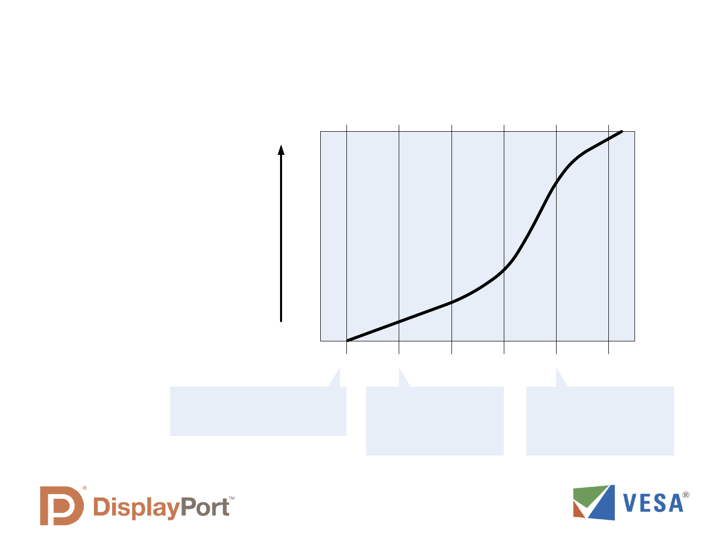
Embedded PC Displays Will Transition
from LVDS to eDP over the Next Few Years
! Integrated GPU
transition from
LVDS to eDP will
be fully complete
in 2013
2009 2010 2011 2012 2013 2014
LVDS
eDP
0%
100%
LVDS no longer
supported by
integrated GPU’s
First Production
Year for eDP
Notebooks
Initial eDP Spec
Released Dec 2008

How does eDP compare to DisplayPort or iDP?
DisplayPort™
• External display Interface
• Needs to interoperate with any external DP Display
• Many optional features tailored for external display flexibility:
HDCP, audio, dual-mode adapters, multi-stream, etc
Embedded DisplayPort (eDP™)
• Internal display interface for PC products
• Uses same GPU video port as external DisplayPort
connections
• Examples where eDP would be utilized:
notebooks, netbooks, notepads, all-in-one systems
• Based on DisplayPort standard with some modifications
Protocol and features optimized for internal display use
• Only needs to interoperate with dedicated system display
Internal DisplayPort (iDP™)
• Internal Interface developed for DTV and display system
products
• Not directly compatible with DisplayPort Standard
• Unique iDP interface and protocol
Optimized for simplicity and extensibility (more data pairs)
Enables very high resolutions and refresh rates
Not applicable for external ports
PC with Embedded Display
GPU or Chipset
DisplayPort
Output
eDP
DisplayPort
Display Panel
TCON
eDP Rx
DisplayPort
Output
DTV with Embedded Display
Video Processor
iDP
Display Panel
TCON
iDP Rx
iDP Output
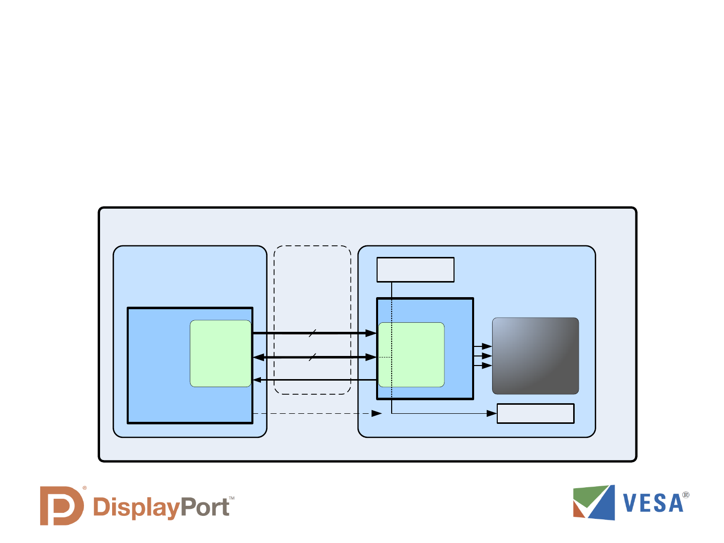
eDP Utilizes the DisplayPort GPU Interface
! No dedicated video port needed for embedded displays (unlike LVDS)
! Main Link lane count of interface can be scaled to fit display data rate
requirements
! AUX Channel and HPD serve as a side-band channel for display
configuration and control
Notebook PC
Motherboard or Video
Subsystem
Display Panel
Main Link
(1 to 4 lanes)
Aux Channel
Backlight control
TCON
eDP
Sink
Function
Video /
Graphics
Processing
Unit
(GPU)
DP or eDP
Source
Function
Display EDID
Memory
LED Backlight
eDP
Interface
HPD
Optional Backlight
Control Signal
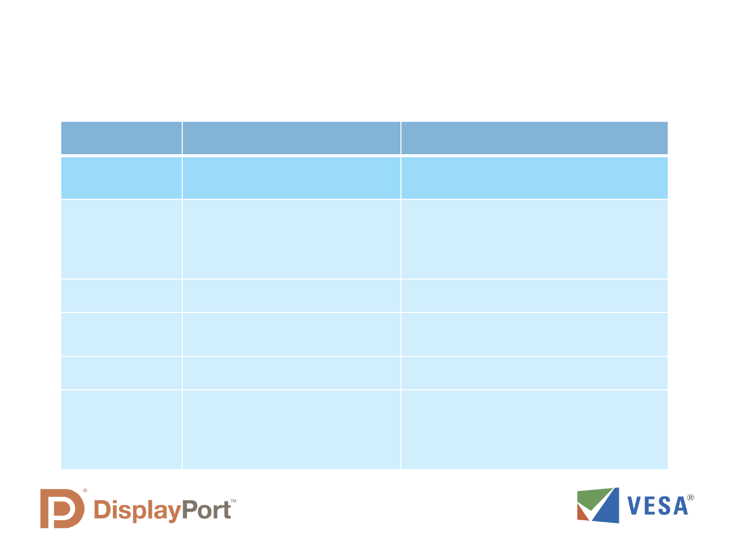
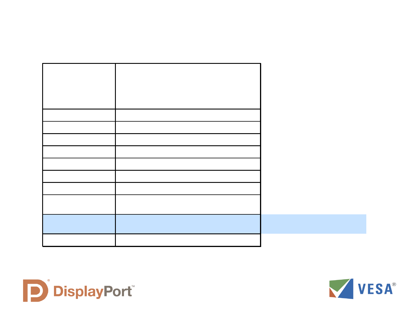
eDP vs. DisplayPort
Compliance and Interconnect
DisplayPort eDP
Overall protocol
and interconnect
Set by standards, consistency
required for external display
interoperability
Flexible, depends on the requirement of the
system and dedicated display
Protocol
Requirements
Covered by DisplayPort Standard and
Compliance Test Specifications
The eDP Standard provides recommended
guidelines, but system integrators may modify
implementation to fit system requirements.
Some specific requirements may be set by the
GPU vendor.
Compliance
Testing
Covered by Compliance Standards
Interface requirement established by system
integrator and/or GPU vendor.
Source-Sink
Interoperability
Covered by the DisplayPort Standard
and other VESA documents
System integrator and GPU vendor determine
eDP Source and Sink requirements.
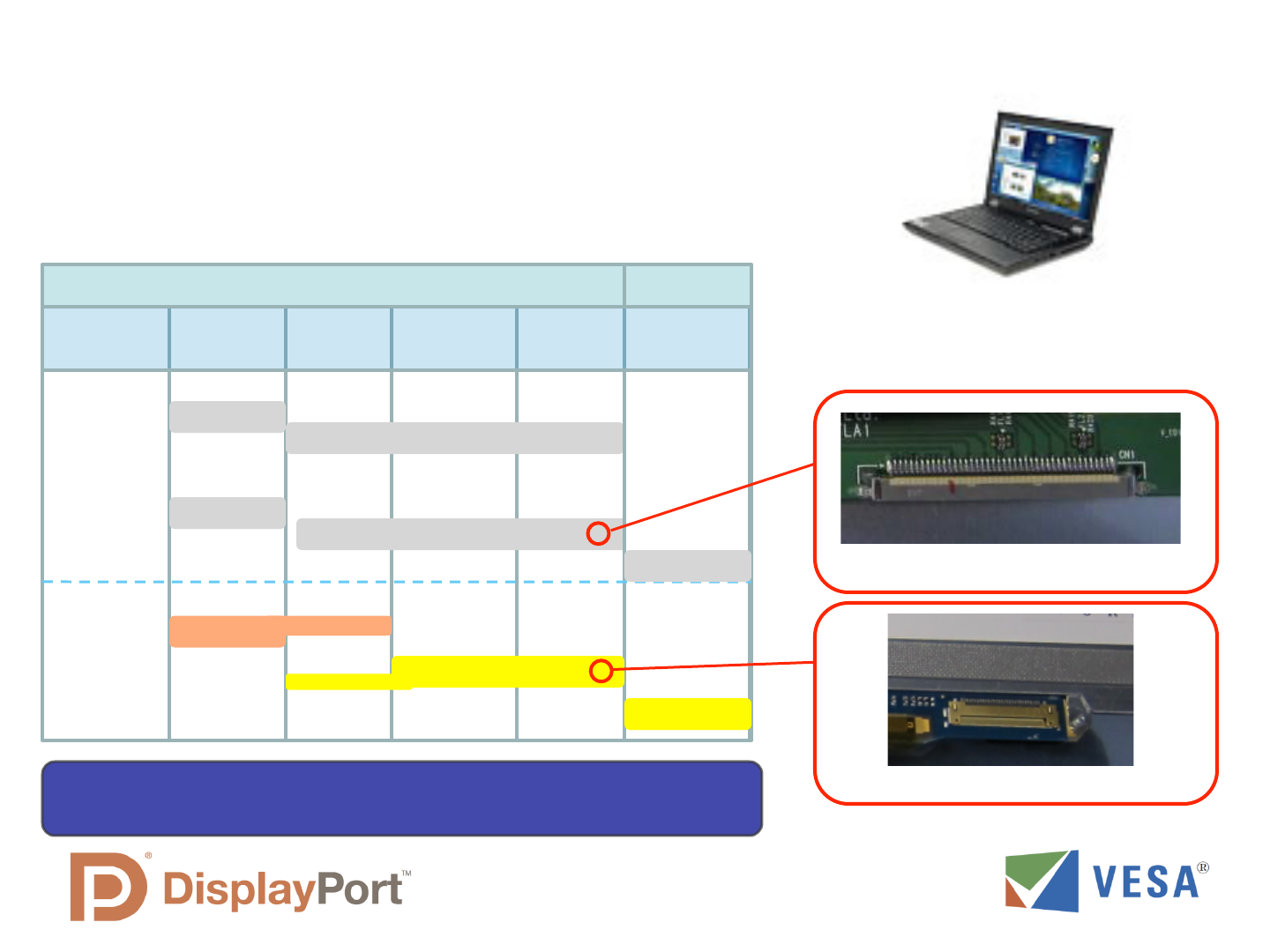
Interface
Connector
Standard or mini-DP connector
30 or 40 pin panel connection depending on
system configuration.
Interface Cable Standard DisplayPort Cable
Different types of cables can be used. Common
cable types include twisted pair and micro coax.
Like the connector, cable choice is determined by
system integrator based on system design
requirements and Source and Sink ability.
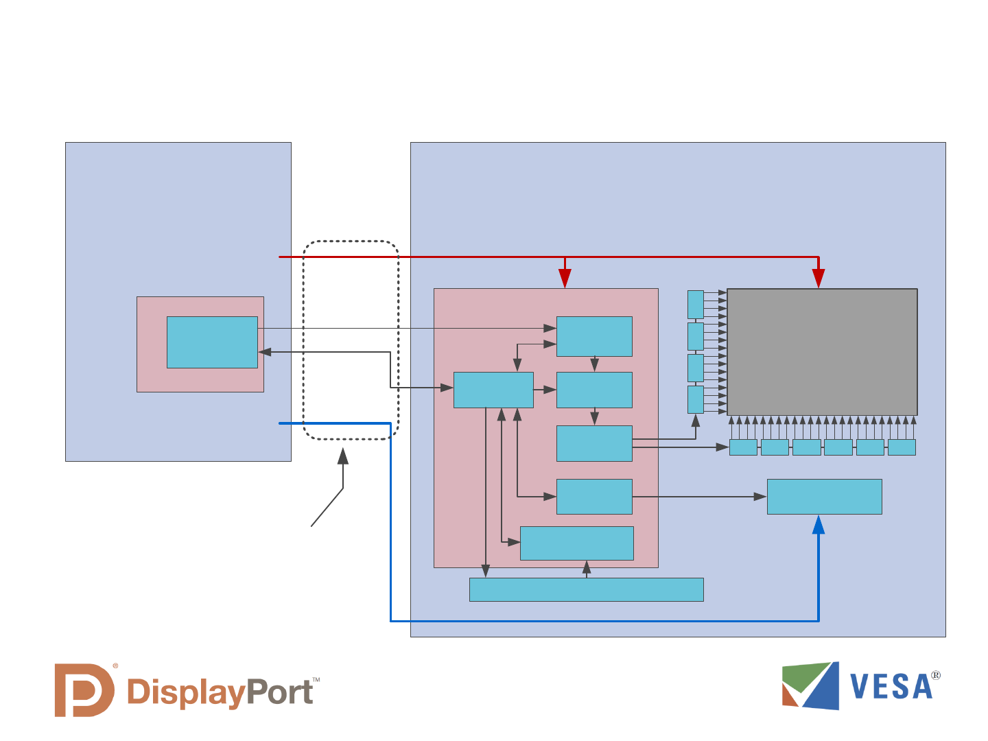
eDP Provides All Panel Connections in One Plug
Includes all power, data and control signals
LCD Panel Assembly
eDP TCON
LCD Display
Column Drivers
LCD
Interface
Pixel
Formatter
eDP ML
Receiver
Row Drivers
PC Motherboard or
Graphics Card
GPU
eDP
Transmitter
Backlight
Control
AUX Ch
Interface
Backlight Driver
Device Status
and Control
EDID and Configuration EPROM
TCON and LCD Power
Backlight Power
eDP Interface Provides the
Complete Panel Connection
Main Link
AUX and
HPD
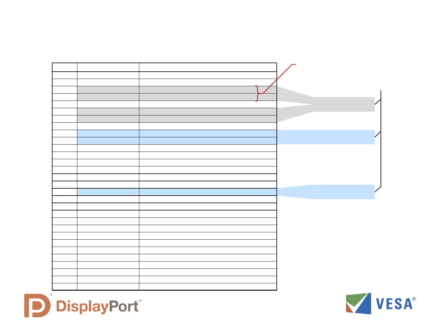
Common Pin Out for eDP Panel Connector
(One or Two lanes, with LED backlight driver on panel)
Table 5-3 in eDP v1.2
Pin
Signal Name
Description
1
NC - RESERVED
RESERVED for LCD manufacturer’s use
2
H_GND
High Speed Ground
3
Lane1_N
Complement Signal Link Lane 1
4
Lane1_P
True Signal Link Lane 1
5
H_GND
High Speed Ground
6
Lane0_N
Complement Signal Link Lane 0
7
Lane0_P
True Signal Link Lane 0
8
H_GND
High Speed Ground
9
AUX_CH_P
True Signal Auxiliary Channel
10
AUX_CH_N
Complement Signal Auxiliary Channel
11
H_GND
High Speed Ground
12
LCD_VCC
LCD logic and driver power
13
LCD_VCC
LCD logic and driver power
14
LCD_Self_Test or NC
LCD Panel Self Test Enable (Optional)
15
LCD_GND
LCD logic and driver ground
16
LCD_GND
LCD logic and driver ground
17
HPD
HPD signal pin
18
BL_GND
Backlight ground
19
BL_GND
Backlight ground
20
BL_GND
Backlight ground
21
BL_GND
Backlight ground
22
BL_ENABLE or NC
Backlight On/Off (Optional)
23
BL_PWM_DIM or NC
System PWM signal input for dimming (optional)
24
NC - Reserved
Reserved for LCD manufacturer’s use
25
NC - Reserved
Reserved for LCD manufacturer’s use
26
BL_PWR
Backlight power
27
BL_PWR
Backlight power
28
BL_PWR
Backlight power
29
BL_PWR
Backlight power
30
NC - RESERVED
RESERVED for LCD manufacturer’s use
!
Optional, depending on
display resolution

Data Carried in eDP Main Link
• Video pixel data
• Video timing information
• Pixel Clock, Hsync, Vsync
• Video format information
• Bits-per-pixel, color space
• Video data error correction
• Audio data (optional)

Data Carried in eDP AUX Channel
• EDID information from Display
(Display Format information)
• Link Training protocol
• Provides a robust main link connection
• Display Control (eDP 1.2)
• Backlight dimming and frequency control
• Dynamic backlight and color enhancement control
• Dithering and FRC (Frame Rate Control)
• Power management
• Error checking of main link data (CRC protocol)
eDP compared to LVDS
! PCB trace and data signal wire count is reduced (smaller cable)
! Signal type more compatible with new chip processes
! eDP can use a DisplayPort GPU interface, no separate video port needed
! Overall system power is reduced, increasing battery life
! Lower EMI which means less system shielding requirement
! Enables new panel control capabilities
Display PanelMother Board
LVDS TX
LVDS RX
Notebook
Hinge
6 Data Pairs
2 Clock Pairs
1 DDC Pair
18 signal wires total
Display PanelMother Board
DisplayPort TX
DisplayPort RX
Notebook
Hinge
1 Data Pair
(with embedded clock)
1 AUX Channel pair
5 signal wires total
1 HPD wire
Comparison of signal
and control wires
For panel sizes up to
1680x1050 with 18 bit
color
(Power and Ground wires
not shown)
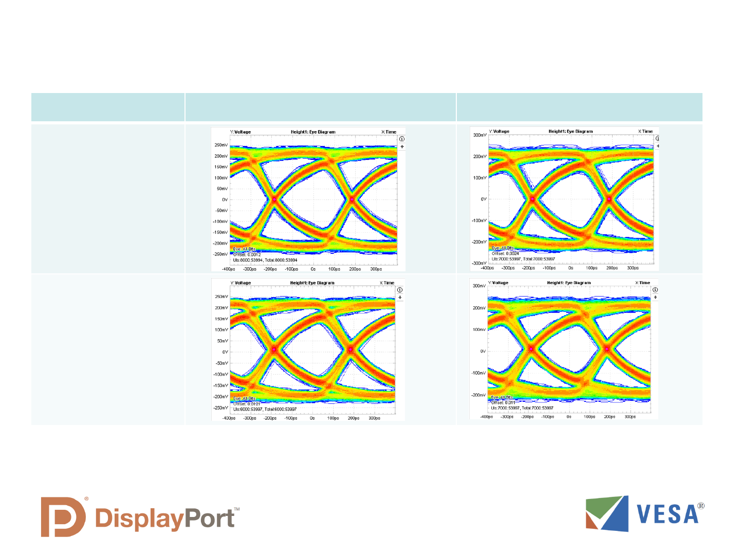
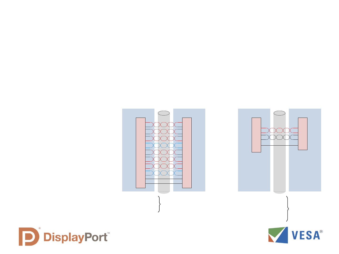
eDP Signal Integrity over Display Interconnect Cable
Measurements at eDP TCON input (TP3) using 400mV swing, 0 dB pre-emphasis by Source
Micro-Coax Cable Twisted-Pair Cable
150mm
Cable Length
150mm
Cable Length
eDP can use the same display cable as LVDS without signal loss or data errors,
while using less conductors
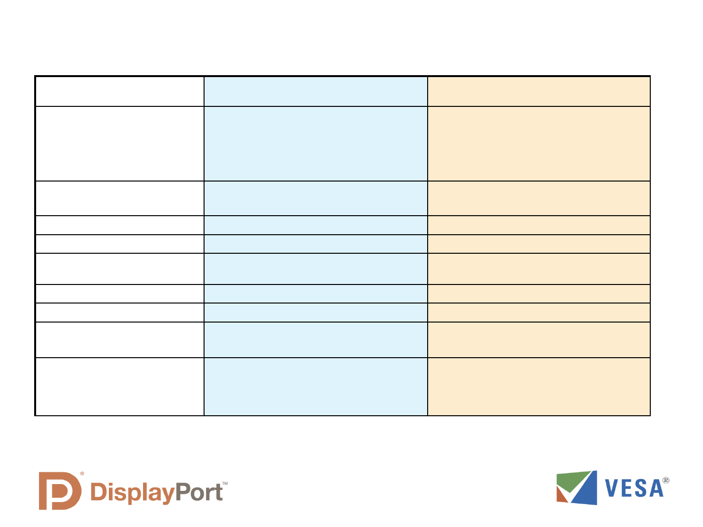
eDP LVDS
No. of data & clock pairs
Example:
1080p@60 Hz, 24bpp:
1 to 4 data pairs,
no separate clock pairs
2 data pairs needed
Higher count of data pairs
Separate clock pair(s) needed
8 data pairs needed (8 data, 2 clock)
(dual channel)
Bit rate, per pair 1.6 , 2.7, or 5.4 Gbit/sec
(fixed clock rate) Future extensible
945 Mbit/sec
(at max 135Mhz pixel clock rate)
Total raw capacity 1.6 to 21.6 Gbit/sec 7.56 Gbit/sec (for dual channel)
Clock Embedded Separate clock pair per channel
Transport Type Packetized for display, audio and other
transport data; Extensible format
Limited to uncompressed pixel raster scan
only
Bi-Directional Data channel 1 Mbps or 720 Mbps (AUX or Fast AUX) 100 kHz (DDC channel)
Channel Coding ANSI 8B/10B Serialized at 7x pixel clock rate
Content protection eDP Display Authentication
HDCP Optional
None
Signal Characteristics AC -coupled, typically 600mV pk-pk swing DC coupled, 700 mV pk-pk signal at VDD/
2 offset.
DDC channel is DC-coupled referenced to
VDD with a 2V swing
eDP compared to LVDS
eDP has Fewer Signal Wires than LVDS
eDP = fewer/more useful pins
– 2.5X to >4X more efficient than LVDS
– Enables slimmer cable than LVDS
Mode
Resolution
HD
1366 x 768
HD+
1600 x 900
FHD
1920 x 1080
FHD+
1920 x 1200
LVDS
eDP
8 signal wires
16 signal wires
18-bit, 24-bit
18, 24-bit
18-bit, Dual Ch
18-bit, Single Ch
4 signal wires
eDP
LVDS
20 signal wires
10 signal wires
20 signal wires
24-bit, Dual Ch
24-bit, Single Ch
eDP fewer pins enable high quality picture
in small form factor
Notebook Example:
13.1 small form factor
1920x1080, 24-bit
2 signal wires (1-lane)
24-bit
18-bit
Frame Rate: 60Hz 120Hz
FHD+
1920 x 1200
40 signal wires
24-bit, Quad Ch
4 signal wires (2-lane)
24-bit
8 signal wires
(4-lane)
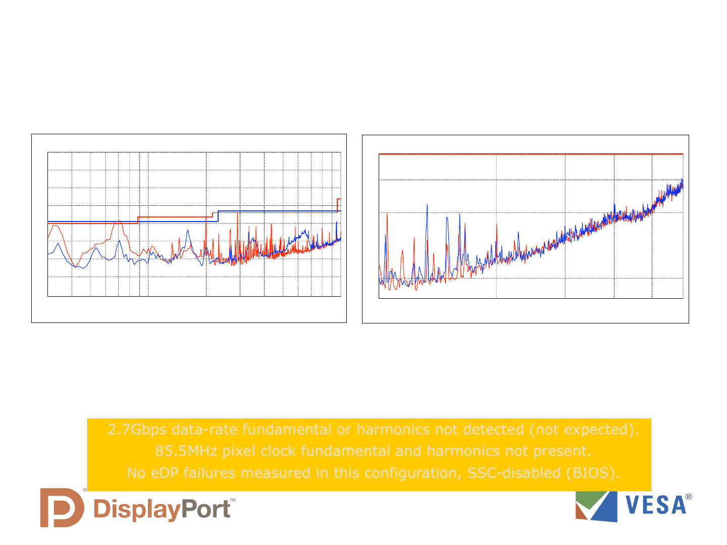
eDP vs. LVDS 3m EMI Scans
• Comparison in native resolution 1366 x 768, 60-Hz, 85.5MHz pixel clock
• eDP 2.7Gbps data link rate.
• Note: LVDS and eDP connect differently in chassis, may result in different EMI
profiles.
0
10
20
30
40
50
60
70
80
Level [dBµV/m]
30M 50M 70M 100M 200M 300M 500M 700M 1G
Frequency [Hz]
+
LVDS
eDP
32
35
40
45
50
54
Level [dBµV/m]
1G 2G 3G 4G 5G 6G
Frequency [Hz]
LVDS
eDP
• LVDS shows higher EMI profile up to 1GHz.
• eDP margins very good, 4 dB+ <1 GHz, and 8 dB+ >1 GHz.
• EMI doesn t align to pixel clock harmonics.
• LVDS may have more cable radiation; higher LVDS EMI may be due to longer and tighter
routing to MB.
2.7Gbps data-rate fundamental or harmonics not detected (not expected).
85.5MHz pixel clock fundamental and harmonics not present.
No eDP failures measured in this configuration, SSC-disabled (BIOS).
Evolution of the eDP Specification
eDP Specification versions and new features introduced
eDP Version
Primary New
Features
VESA
Standard
Release
First System
Model Year
eDP v1.0
Initial eDP
Standard
December 2008
2009
(system
prototypes only)
eDP v1.1
Minor changes
and clarifications
October 2009
2010
(systems now
in production)
eDP v1.2
Added display
control through
AUX channel
May 2010 2011
eDP v1.3
Adds Panel Self-
Refresh
Capability
January 2011
(Expected)
2H 2012
(forecast)
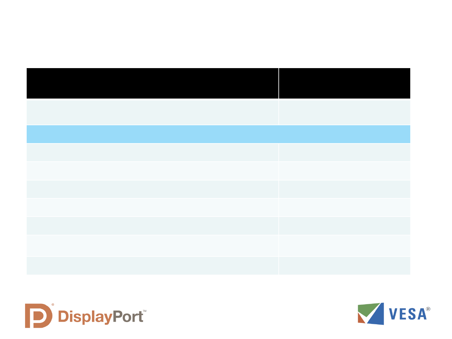
eDP vs. DisplayPort
Key Protocol Differences
DisplayPort eDP
Content
Protection
HDCP is the only content protection
protocol used; used by many systems
HDCP – optional, but rarely used.
Other simplified options available for
eDP; Most common is ASSR which
stands for Alternate Scrambler Seed
Reset .
(saves power and complexity)
Interface Link
Training at
Power-on
Full link training protocol required
System can be configured to use fast
link training (simplified protocol) or no
link training (no training protocol,
designed for fastest display re-enable
time)
640 x 480 Safe
Mode
Required
Not required; GPU always supports native
display resolution.
Special Power
Saving Modes
Only Standby and Power Down
Display timing adjusted to reduce power,
depending on display image motion.
Backlight and
Other Display
Control
MCCS Only
Special AUX Channel Registers for eDP
use
(introduced with eDP v1.2)
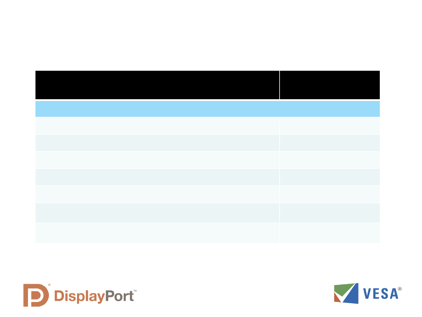
eDP Display Control Through AUX Channel
Capability Introduced with eDP 1.2
DPCD Address
Range
(Hexidecimal)
Application Category
000-0FF Receiver Capabilily
100-1FF Link Configuration
200-217 Link/Sink Status
218-2FF Automatic Testing (Optional)
300-3FF Source Device-Specific
400-4FF Sink Device-Specific
500-5FF Branch Device-Specific
600-6FF Sink Control
700-7FF Reserved for eDP
800-FFF Reserved for future use
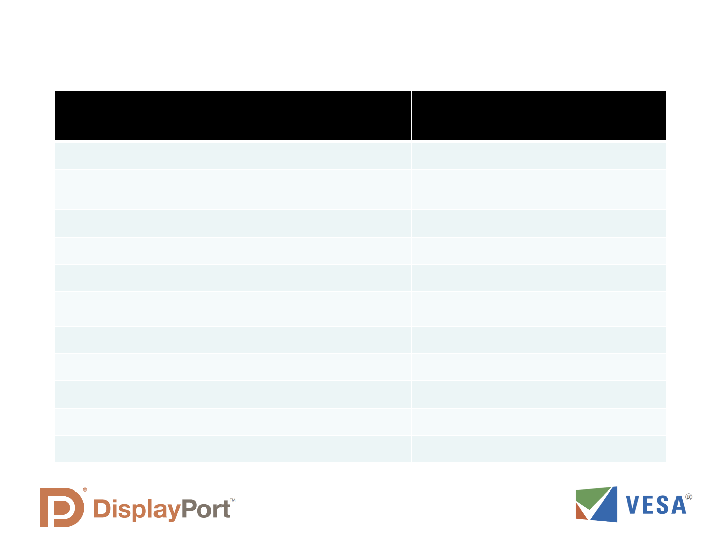
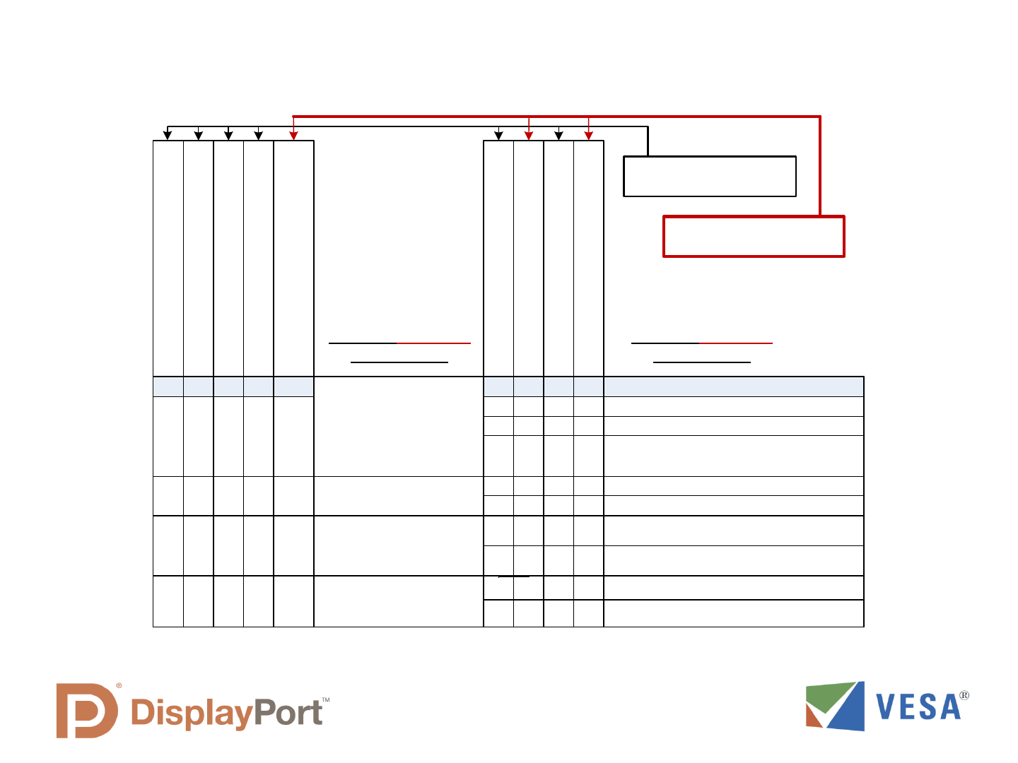
eDP v1.2 Sink Control Capability
Capability Reported Through DPCD Field 700h Register Read
Capability Supported, Read Through
AUX Channel
Notes
eDP v1.2 Support Capability First capability read by
Source
General Control Capability
Supports Backlight Adjustment through AUX
Supports Backlight Enable through AUX
Supports Backlight Enable through connector pin
Optional in eDP v1.2
Supports Backlight Enable through connector pin
Optional in eDP v1.2
Supports FRC Capability, controlled through AUX
Supports Color Engine Capability, controlled through
AUX
Supports power state control through AUX
eDP v1.2 Sink Control Capability (continued)
Capability Reported Through DPCD Field 700h Register Read
Capability Supported, Read Through
AUX Channel
Notes
Backlight Adjustment Capability
Supports Brightness control through connector PWM pin
Optional in eDP v1.2
Supports Brightness control through AUX
Supports combined AUX-PWM brightness control
Supports Backlight freq control from PWM pin
Supports Backlight freq control through AUX
Supports dynamic brightness control, controlled through
AUX
Supports Brightness control through the connector PWM
pin
eDP v1.2 Sink Control Capability (continued)
Control Available Through DPCD Field 700h Register Write
Control Supported Through the
AUX Channel
Notes
Backlight Enable (uses DPCD register 001Ah)
Removes an interface conductor
Black Video Enable
Also automatically enabled with
detection of invalid video
FRC Enable
Color Engine Enable
Dynamic Backlight Mode Enable
Min and max brightness for dynamic backlight
mode
Backlight brightness control mode
Backlight brightness set (up to 16 bit resolution)
Removes an interface conductor
Backlight frequency control mode
Backlight frequency set
Self-Test Enable (uses DPCD register 001Ah)
Removes an interface conductor
Summary of eDP v1.2 Backlight Control Settings
Table 3-19 from eDP v1.2, simplified
!"#$%&'()*+,-*#.//0#).1*+&/
!"#$%&'()*"23*40)*#"+"!%0
!"#$%&'()*5"23675+,-6*#"+"!%0
289*:;9<89=*>?@A9*BC*:?D9@
49=*EF*+,-*GA=F*HFH@9*
98=?E@I8J9G*EF*GA=F*HFH@9*
9K+*HBDD9H=B;*:IDL*IC*
?>?I@?E@9
Backlight*Brightness*
Control*Mode
!?HM@INJ=*!;INJ=D988*89=*
=J;A*"23*HJ?DD9@
49=*EF*:;BGAH=*BC*+,-*
>?@A9*BD*HBDD9H=B;*:ID*?DG*
"23*HJ?DD9@*>?@A9
!1&'()/044*#./)1.%*-.K0
0 1
0 0
1 0
1 1
K#K#K#
K#K#O
K#OK#
OOO
K#*P*KBDQ=*#?;9
+,-*+&/*R10S*+"44<)(12*#"+"!&%0
"23*40)*+,-*R10S*#"+"!&%0
Backlight*Frequency*
Control*Mode
289*:?D9@*:;9<89=*E?HM@INJ=*C;9TA9DHF
+,-*+&/*R10S*+"44<)(12*0/"!%0
"23*40)*+,-*R10S*0/"!%0
K#K#K# U
OK#K# O !?HM@INJ=*R;9TA9DHF*89=*=J;A*"23*HJ?DD9@
K#UK# U
OK#K# O
K#OO U
289*:?D9@*:;9<89=*E?HM@INJ=*C;9TA9DHF
49=*EF*+,-*C;9TA9DHF*ID=B*!%V+,-VK&-*
:ID*BD*9K+*HBDD9H=B;
K#K#K# U
OK#K# O
289*:?D9@*:;9<89=*E?HM@INJ=*C;9TA9DHF
K#K#K# U
OK#K# O
289*:?D9@*:;9<89=*E?HM@INJ=*C;9TA9DHF
!?HM@INJ=*R;9TA9DHF*89=*=J;A*"23*HJ?DD9@
!?HM@INJ=*R;9TA9DHF*89=*=J;A*"23*HJ?DD9@
!?HM@INJ=*R;9TA9DHF*89=*=J;A*"23*HJ?DD9@
)#./*!"#$%&'()*"KW*#"+"!%0
UK#U K# )B*E9*8:9HICI9G*EF*:?D9@*>9DGB;
O
O
O
U K#UUU
O
Capability Registers in
eDP Panel (read only)
Configuration Registers
in eDP Panel
LCD Panel Assembly
eDP TCON
LCD Display
Column Drivers
LCD
Interface
Pixel
Formatter
eDP ML
Receiver
Row Drivers
PC Motherboard or
Graphics Card
GPU
eDP
Transmitter
Backlight
Control
AUX Ch
Interface
Backlight Driver
Device Status
and Control
EDID and Configuration EPROM
TCON and LCD Power
Backlight Power
Main Link
AUX and
HPD
Video
Frame
Buffer
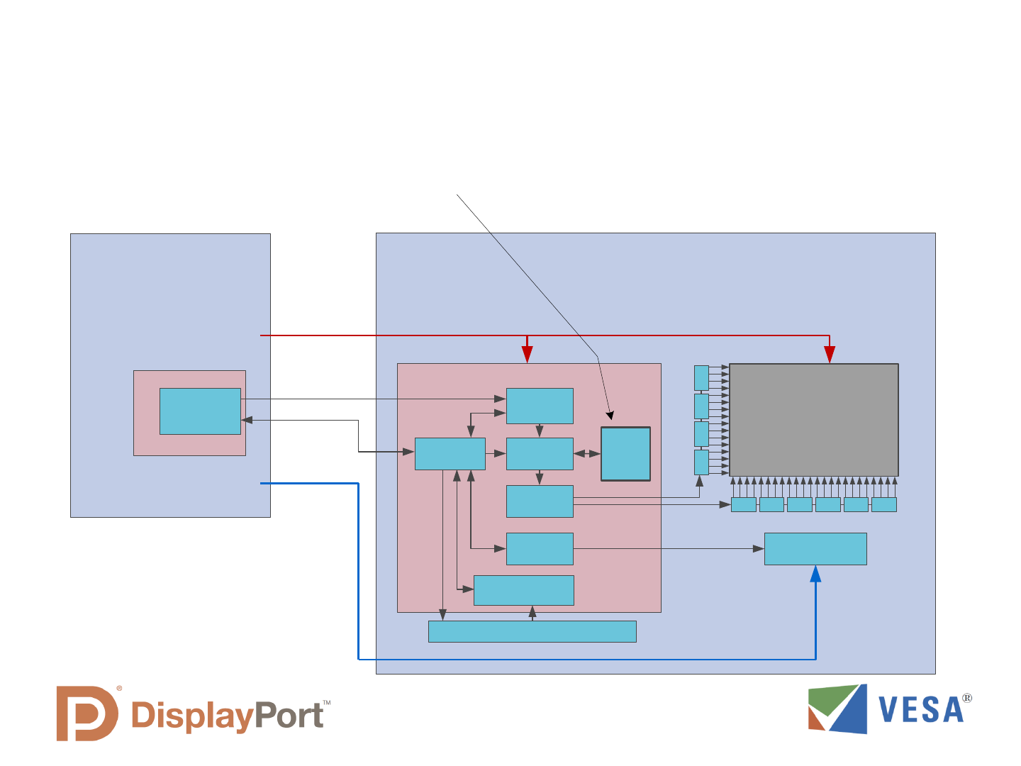
Remote Frame Buffer Will
be Added to Display
Main New Feature for eDP 1.3:
Panel Self-refresh
Frame buffer can also be
used for LCD overdrive to
improve 3D performance

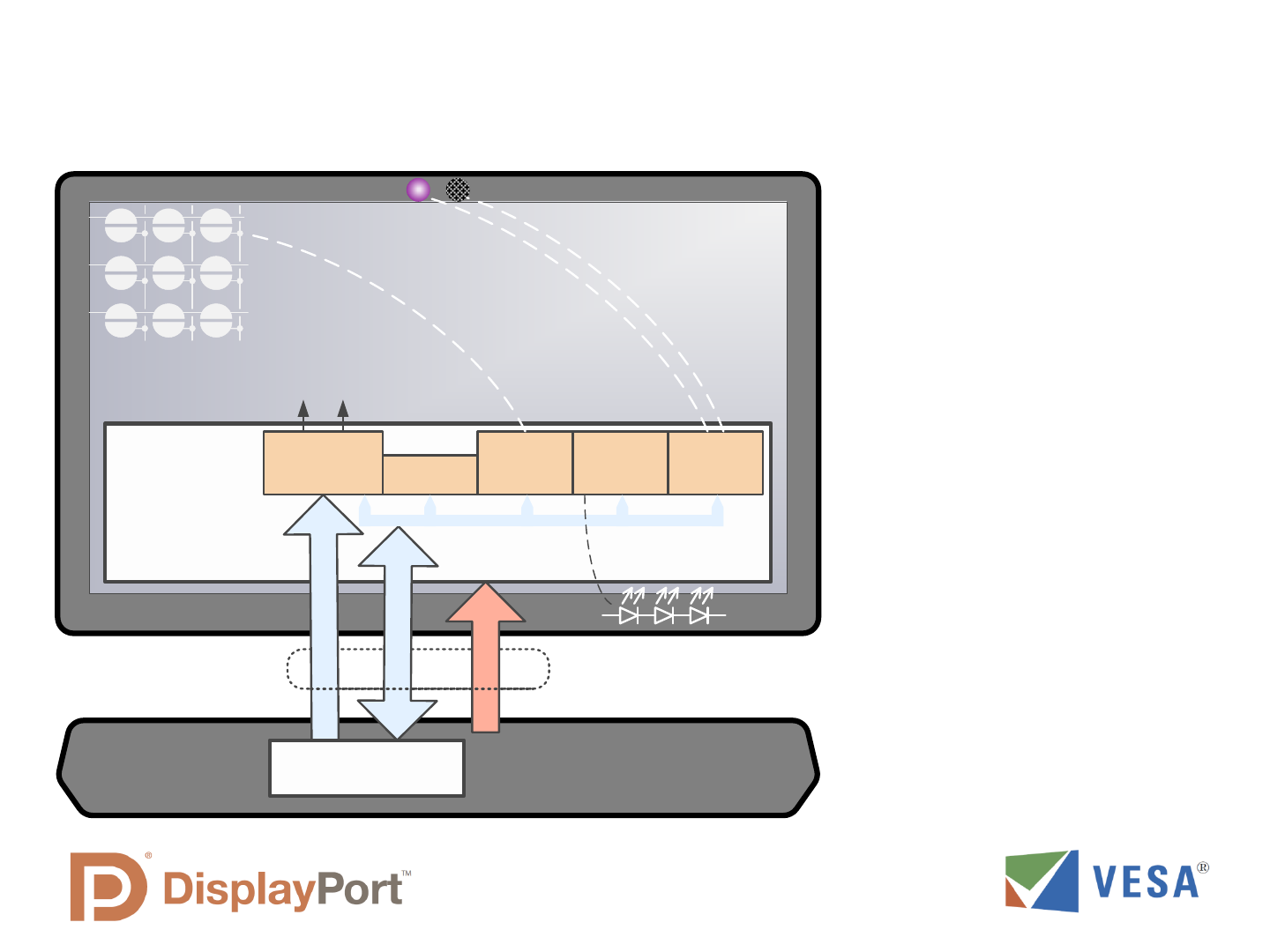
Description of Panel Self-refresh
• Frame Buffer in TCON can maintain display image without
receiving video data from GPU.
• For a still video image, this allows the GPU to enter a low
power state and the eDP main link to turn off.
• Allowing the GPU to power down between display updates
will save significant power and extend battery life.
• Except when watching a movie or playing a game, there
are many times when the video does not change for
multiple frames.
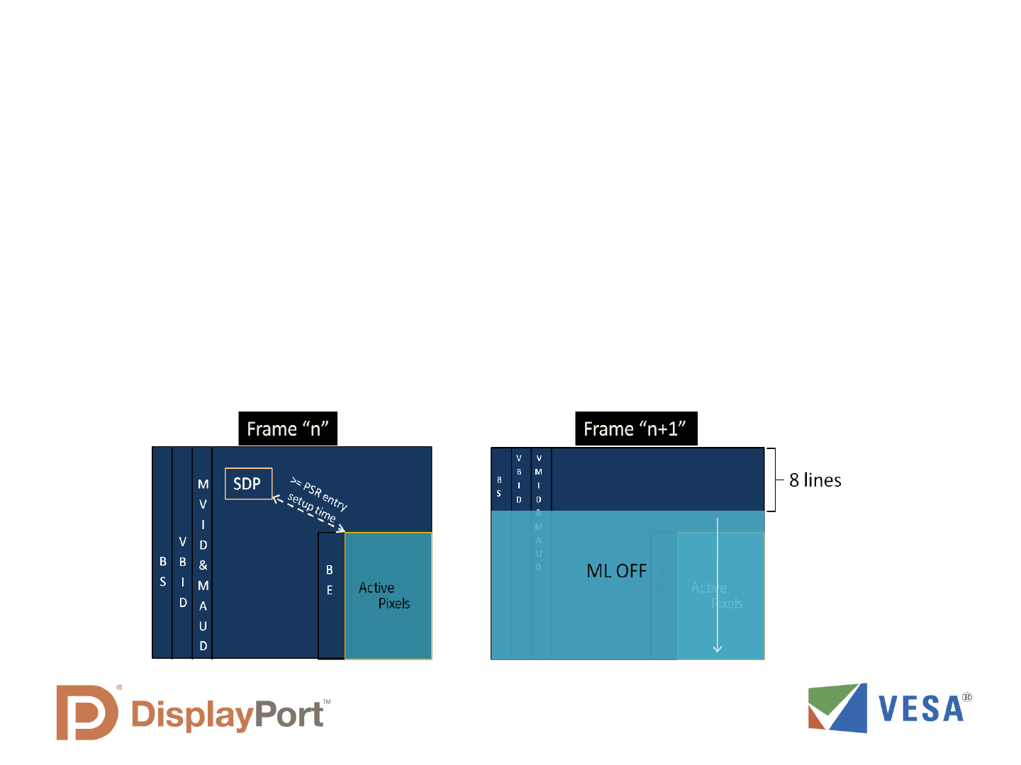
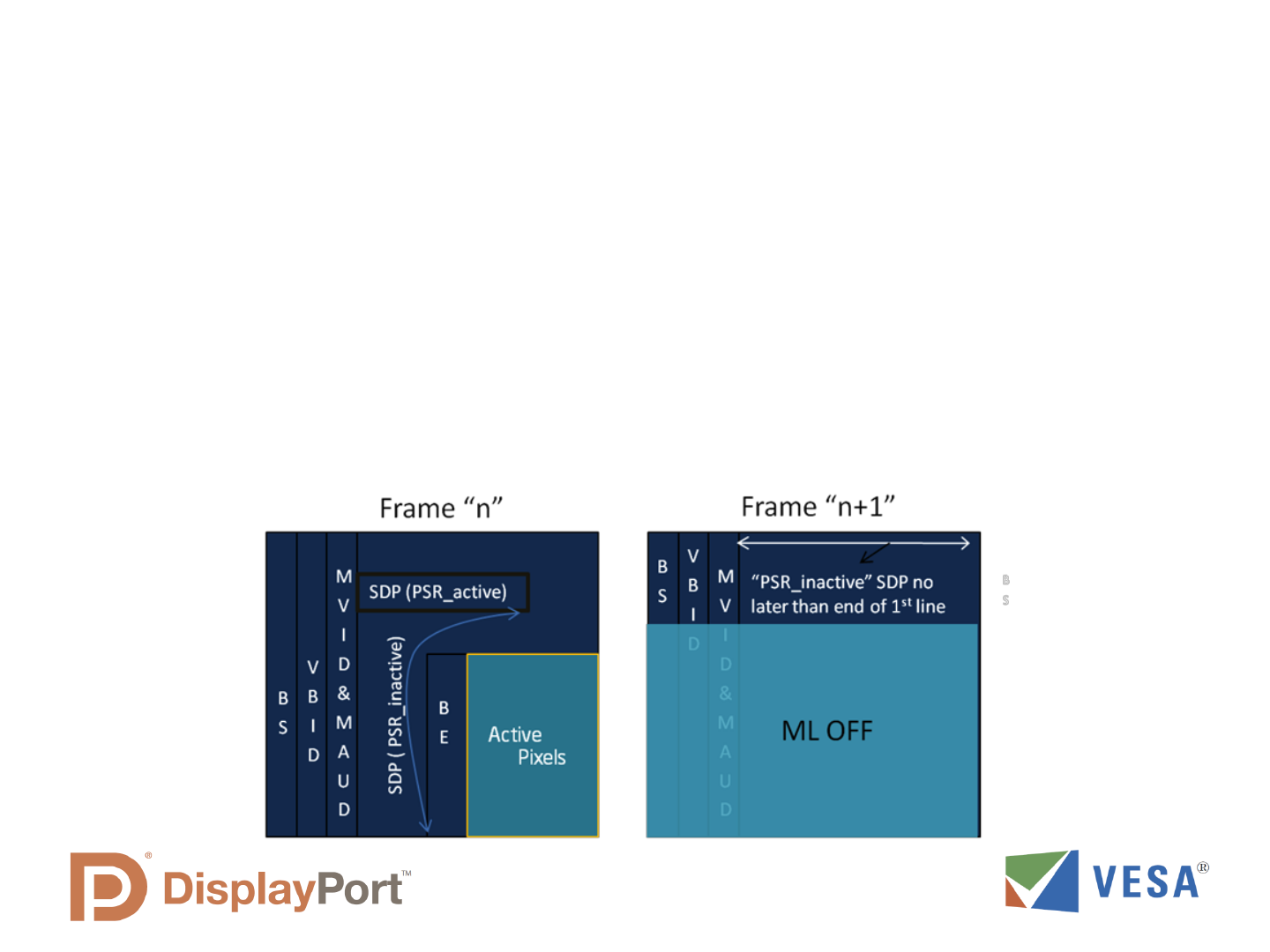
How Panel Enters Self-refresh Mode
• GPU determines when display will not be changing
and sends Self-refresh Entry command to display
using SDP (secondary data packet); TCON then
enables frame buffer, captures video frame, and
then GPU and Main Link turn off.
• Display continues to Self-refresh from TCON frame
buffer, using asynchronous timing for display.
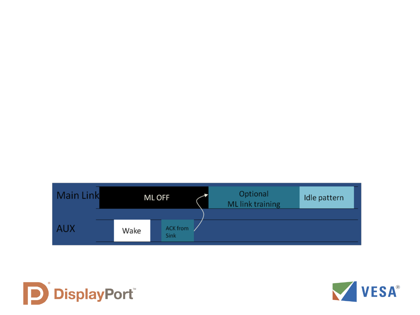
How of Panel Exits Self-refresh Mode
• When GPU detects new image data (for example from a
keystroke or mouse movement), GPU wakes up TCON
eDP input and starts sending the new display image data.
• Display then switches from the Frame Buffer to eDP input
data, and Genlocks display timing to GPU.
Single Frame Update
• While in Self Refresh Mode, the GPU can make single
frame updates to the TCON frame buffer; the display
maintains asynchronous timing during the process.
• This can be used to turn on or turn off a blinking display
cursor, for example.
• A burst of single frame updates can also be used, for
example to fade-in and fade-out the blinking cursor.
The Future of eDP
Helping to Enable Further Display Integration
Camera & Mic
Integrated
Display Chip
eDP Tcon
Touch
Control
USB
Hub
ROM
B/L
Control
M
a
i
n
L
i
n
k
AUX
Ch
an
n
el
Power
GPU
eDP Interface
• eDP provides a unified
data & control path to the
display system
• The packetized structure
of DisplayPort enables
continued extension of
data types and function
support
• eDP will help enable
highly integrated display
platform chips and
reduce required
interconnect across the
notebook display hinge

Q&A
