DISTRIBUTION STATEMENT A: Approved for public release; distribution is unlimited
PCN 32002407000
DISTRIBUTION RESTRICTION: Approved for public release; distribution is unlimited.

FM 24-2
Chapter 1
International Spectrum Management
1-1. Introduction
All nations share the electromagnetic spectrum and
reserve their right to its unlimited use. However, for
international telecommunications cooperation to support
trade, transportation, communications, and mutual
protection against interference, they have agreed to an
International Telecommunications Convention. This
serves as the basic instrument of the International
Telecommunications Union (ITU) and its supporting
bodies. This chapter covers this organization and
relationship with the US.
1-2. The ITU
The United Nations recognizes the ITU as the
specialized agency in the telecommunications field. The
ITU maintains cooperation to improve all
telecommunications. The ITU allocates the international
radio frequency (RF) spectrum, registers frequency
assignments, and coordinates resolving interference. Upon
ratification by member nations, ITU regulations have
treaty status. Each ITU member nation imposes regulatory
measures within its administration. These measures must
comply with the current Radio Regulations (RR) unless
expressly excluded by either footnotes or by special
arrangements.
1-3. The ITU Organization
The Plenipotentiary Conference is the supreme agency
of the ITU. It formulates general policies, establishes
budgetary guidelines, elects members, and concludes
agreements between the ITU and other international
communications organizations. The ITU has three
organizations or agencies that directly affect Army
spectrum management: the World Administrative Radio
Conference (WARC), the International Frequency
Registration Board (IFRB), and the International Radio
Consultative Committee (CCIR).
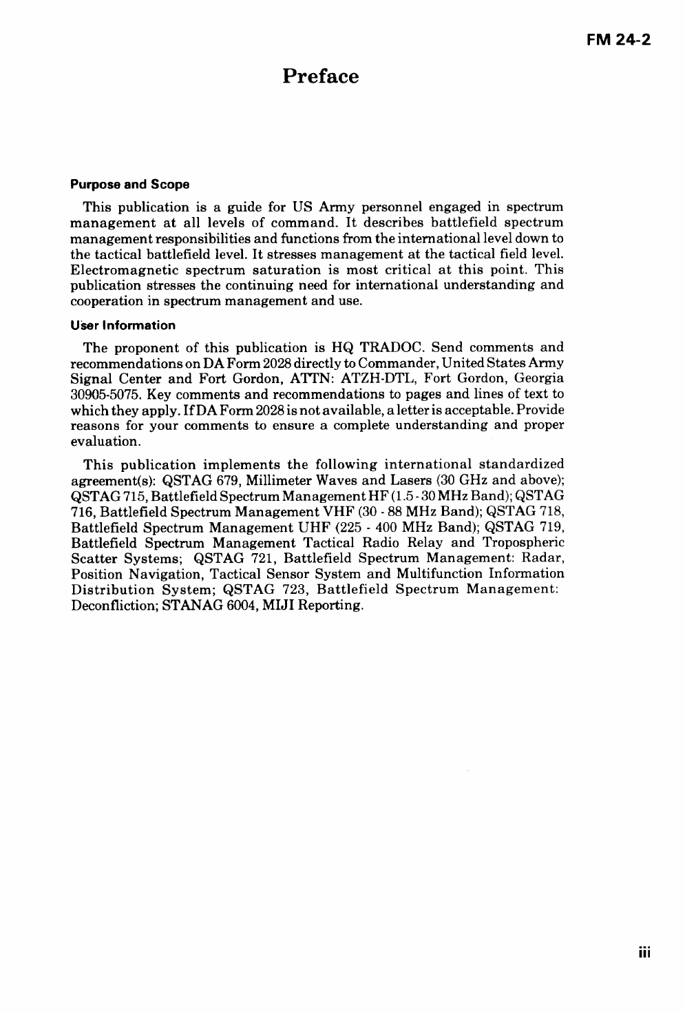
A WARC may deal with all of the radiocommunications
services, or it may deal with specific radiocommunications
services such as space, maritime, or aeronautical. Each
WARC updates the RRs which allocate radio spectrum
use on a worldwide basis except where regional
requirements differ and are agreed. Figure 1-1 shows the
three recognized regions. In addition, the tropical area
centered on the equator has additional provisions to offset
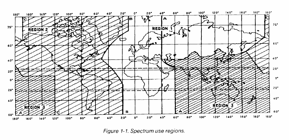
its higher electrical noise. Figure 1-2 shows all the uses of
radio spectrum that are managed by services. Exceptions
to these allocations may be footnotes for specific countries
or reservations made by that country at the WARCs.
1-1
FM 24-2
The lFRB records ITU member nation frequency
assignments. It advises the WARCs and member nations
on technical matters on harmful interference and radio
spectrum
US
e. The IFRB serves as the office of record of
frequency assignments in priority and adjudicates
interference conflicts among member nations.
The CCIR provides technical criteria on frequency
sharing and examines technical and operational questions
about international radio use. It also addresses technically
related questions pertinent to ITU member nations and
forthcoming WARCs. The findings of the CCIR serve a
significant influence on the state-of-the-art and as a basis
for RRs. However, these findings are recommendations
rather than having an obligatory treaty status. The CCIR is
organized into study groups. The United States Study
Groups (USSGs) submit their investigations or findings
through the National Committee. This is described in the
next paragraph. In addition to study groups on radio
propagation, the Army is concerned with the study group
on the mobile radiocommunications services.
1-4. The Department of State
Bilateral and multilateral negotiations and agreements
concerning telecommunications and spectrum use are es-
sential to foreign relations. The Department of State is
responsible for such negotiations. It also reviews and
directs the US positions using personnel and experts in
government, industry, and academic fields. It also relies on
the recommendations of the National Telecommunica-
tions and Information Administration (NTIA), the Federal
Communications Commission (FCC), other government
agencies, and private sector organizations when designat-
ing delegations to international or regional ITU conferen-
ces or meetings. The State Department governs US
participation in the CCIR, and it chairs a United States
National Committee (USNC). The USNC consists of rep-
resentatives of federal government agencies with a vested
interest in telecommunications. The USNC gives final ap-
proval on all US contributions to the CCIR. USSGs have
been set up by charter to review foreign contributions to
the CCIR. This review helps US delegations prepare sum-
maries, critiques, and impact assessments for international
meetings.
1-2
FM 24-2
Chapter 2
National Spectrum Management
2-1. Introduction
The Communications Act of 1934, as amended, governs
radio spectrum use in the United States and its possessions
(US&P). The act established duality in spectrum
management in the US between the President for federal
government stations and the FCC under the direction of
Congress. The FCC regulates the spectrum use of
nonfederally operated radio stations, common carriers,
and private organizations or individuals. By Executive
Order 12016 of 1978, the President delegated his functions
under the act to a new organization created as the NTIA
and placed them under the Secretary of Commerce. This
chapter discusses these agencies and their functions in
national spectrum management.
2-2. The NTIA
The Communications Act of 1934 gave control of
government radio stations to the President. The President,
through the NTIA, will--
Control all frequency resources in the US&P.
Authorize foreign governments to construct and
operate fixed service radio stations at their embas-
sies. (Frequencies are assigned to these stations if
it is in the national interest and if foreign govern-
ments grant reciprocal privileges to the US.)
Two committees advise the NTIA and serve essential
spectrum management functions.
The Frequency Management Advisory Council,
established in 1965, consists of experts from the civil sector
who meet when necessary to make recommendations on
spectrum management and electromagnetic compatibility
(EMC).
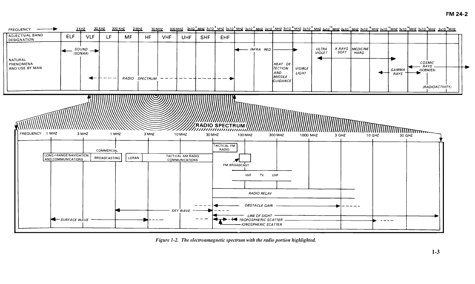
The Interdepartmcnt Radio Advisory Committee
(IRAC), established by Presidential Order in 1922, is the
policy-making agency of the NTIA. Most often, spectrum
managers deal with this committee. Figure 2-1 shows the
representatives from government departments or agencies
which make up the IRAC.
Four subcommittees carry out the IRAC’s daily
functions. These are the Frequency Assignment
Subcommittee (FAS), the Spectrum Planning
Subcommittee (SPS), the Technical Subcommittee (TSC),
and the International Notification Group (ING).
The FAS recommends approval of frequency
assignments for government radio stations to the Director
of NTIA. The Aeronautical Assignment Group (AAG)
and the Military Assignment Group (MAG) make up the
FAS.
The Federal Aviation Administration (FAA) chairs the
AAG. The Navy, Air Force, and Army make up this group.
The AAG approves frequency assignments for
aeronautical operations.
The MAG has the same members and is chaired by the
Air Force. The MAG approves frequency assignments for
nonaeronautical operations.
The SPS supports the IRAC and the NTIA in planning
RF spectrum allocations for established or developmental
radio services. The SPS maintains a direct liaison with the
FCC.
The TSC assists the Director of NTIA on using signal
equipment and techniques and in establishing
performance standards for equipment. It also researches
ways of ensuring effective RF spectrum use.
The ING is responsible for all correspondence with the
ITU on US frequency assignments.
2-3. The FCC
The Communications Act of 1934 created the FCC as
an independent government agency directly responsible to
Congress. The FCC regulates nonfederal government
telecommunications.
•
•
2-1
FM 24-2
2-2
FM 24-2
The FCC maintains a liaison at all IRAC meetings and
works with its subcommittee even though the FCC is not
an IRAC member. The liaison is the crossover point for
spectrum management actions requiring FCC
coordination.
The FCC conducts its management functions under the
Administrative Procedures Act. Rule-making processes
are administrated with full public knowledge and are
subject to hearings. The FCC will only act on or accept
formal statements from Headquarters, Department of the
Army. However, the FCC will consider personal matters of
Army personnel.
The radio spectrum within the US is divided between
exclusive government, exclusive FCC, and bands shared by
both. An example of an exclusive government band is 225
to 400 MHz and is designated for military use. Exclusive
FCC management is shown in broadcasting bands.
Government and nongovernment users share 60 percent of
the radio spectrum (up to 5000 MHz).
2-4. Office of Management and Budget
Following Executive Order 12016, the Army’s right of
appeal to an unacceptable radio spectrum decision by the
NTIA or IRAC is to the Director of the Office of
Management and Budget (OMB).
OMB Circular A-11 directs that before acquiring
spectrum-dependent equipment, RF supportability shall
be documented as early as possible during concept
exploration, demonstration, and validation stages. This is
reflected for Department of Defense (DOD) agencies in
DOD Directive 4650.1.
2-3
FM 24-2
3-1. Introduction
Chapter 3
DOD Spectrum Management
The DOD and each military service have their own
spectrum management agencies. This chapter identifies
and describes the functions of these agencies.
3-2. The DOD
The deputy under secretary for command, control,
communications, and intelligence (C3I) is responsible for
DOD spectrum management policy. Within the US&P, the
three military services representatives coordinate
spectrum management through the IRAC. Outside the
US&P, these services coordinate spectrum management
through military channels.
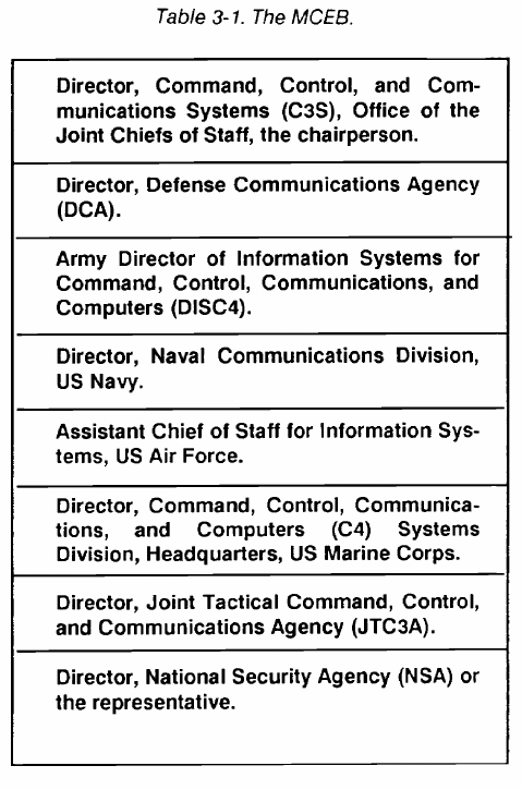
3-3. Military Communications-Electronics Board
The Military Communications-Electronics Board
(MCEB) is the main coordinating agency for signal matters
among DOD components, between the DOD and other
government departments and agencies, and between DOD
and foreign nations. (See Figure 3-l.) The MCEB
functions under the policies and directives of the Secretary
of Defense and the Joint Chiefs of Staff (JCS). The MCEB
guides the DOD in preparing and coordinating technical
directives and agreements and in allocating spectrum
allotments from the NTIA. DOD directives state that DOD
components will obtain MCEB guidance before assuming
contractual obligations for developing or procuring
telecommunications equipment purposely designed to
radiate or receive electromagnetic energy. Table 3-1 lists
the members comprising the MCEB.
3-4. The Joint Frequency Panel
The joint frequency panel (JFP) is the principal DOD
coordinating agency for spectrum management. This panel
works closely with the IRAC’s FAS. The JFP reviews,
develops, coordinates, and implements DOD directives,
studies, reports, and recommendations for the MCEB.
Study areas include RF engineering and management,
radio wave propagation, and EMC. With the addition of
the Coast Guard, membership in the JFP is the same as the
MCEB.
3-5. DOD Area Frequency Coordinators
DOD area frequency coordinators (AFCs) coordinate
field use of RFs within designated frequency ranges and
geographic areas. Frequencies used in these areas must be
coordinated with the appropriate DOD AFC before
making a frequency assignment. See Appendix C for
additional information.
3-1
FM 24-2
3-2
FM 24-2
3-6. Electromagnetic Compatibility Analysis
Center
The Electromagnetic Compatibility Analysis Center
(ECAC) advises and assists the Secretary of Defense, the
JCS, military departments, other DOD components, and
civilian agencies on EMC matters. The ECAC maintains
the data bases and mathematical and computer analysis
techniques for investigating DOD and interservice EMC
problems.
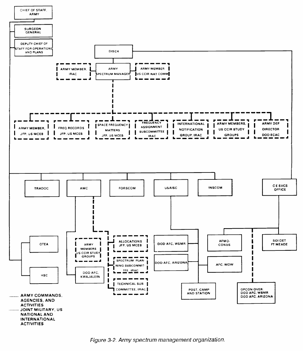
3-7. Army Spectrum Management
The Army spectrum manager in the office of DISC4 has
the functional responsibility for Army spectrum
management. The Communications-Electronics Services
Office and close coordination with major Army commands
directly support the Army spectrum manager. (See AR
5-12.)
The Communications-Electronics Services Office
provides the major coordination and frequency planning at
the Department of the Army (DA) level with the Army
spectrum manager. It also supervises the operation of the
Army Frequency Management Office-Continental United
States (AFMO-CONUS) at Fort Sam Houston, Texas
which consolidated the regional frequency coordination
offices in 1989. Army participation in the national radio
regulatory structure is accomplished at departmental
level
S
with the NTIA, the FCC, and other federal
departments through the IRAC and its subcommittees.
Army spectrum management is decentralized through
major commands, posts, camps, stations, and operating
forces. United States Army Information Systems
Command (USAISC) personnel manages frequency
assignment requirements locally at posts, camps, and
stations. This is normally done through the Director of
Information Management (DOIM) and forwarded to
AFMO-CONUS or the Communications-Electronics
Services Office for action. The installation manager is the
first level of coordination for spectrum managers at
CONUS Army installations. Coordination includes
frequency, equipment, power, emission, and location.
•
By OMB and DOD directives, frequency allocation for
Army development and acquisitions must document
frequency supportability before procurement. This is done
through the JF-12 process using DD Form 1494 and
nationally through the IRAC’s SPS. This task is delegated
to the United States Army Materiel Command (AMC),
and by it, to the Army Communications-Electronics
Command (CECOM). Because of its impact with
operational frequency assignment, the plans and
engineering branch of the Communications-Electronics
Services Office participates in the allocation to equipment
process with CECOM. Frequency allocations to
equipment defines the frequency characteristics of
equipment being procured and indicates its frequency
supportability. Operating this equipment requires the
additional step of frequency assignment for use in the
intended operational environment. EMC is the process of
predicting and controlling potential interference in
allocations planning for new equipment and for frequency
sharing of the equipment in its operating environment.
Figure 3-2 shows the Army organization for spectrum
management.
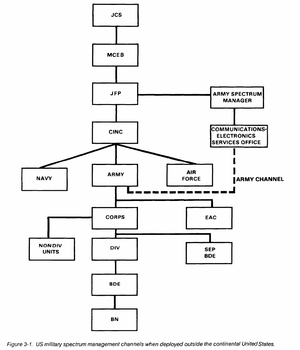
3-8. Unified/Specified Commands, Treaty
Organizations, and Other Foreign Areas
The electromagnetic spectrum is a natural resource
within any sovereign nations boundaries and can be used
only with that nation’s consent. Except forced entry, the
Status of Forces Agreement (SOFA) made with host
nations defines frequency provisions and procedures to be
followed in all frequency and radio regulatory matters.
Unified commands are normally established for
missions requiring significant assigned components of two
or more services. Specified commands are normally
established for missions requiring a force consisting
primarily of units from a single service. The highest
command present controls spectrum management. The
MCEB provides policy guidance. Unified and specified
commanders, subject to host nation agreements, have
overall management and control responsibility for all US
military electromagnetic spectrum use within their
operational zones. Through the Combined
Communications-Electronics Board (CCEB), direct
military channels have been established between the US
and the United Kingdom, Canada, New Zealand, and
Australia. Unified and specified commanders make
frequency assignments for certain intracommand
communications provided--
Coordination has been accomplished with the
government of the host nation, with local US
government agencies such as the FAA, the FCC,
or Army, and DOD AFCs.
•
National or international protection is neither
desired nor required.
•
NTIA and FCC jurisdictional areas are not
involved.
3-3
FM 24-2
•
Harmful interference with authorized users
registered with the NTIA, the IFRB, or the host
nation will not result.
The Allied Radio Frequency Agency (ARFA) is
responsible for all North Atlantic Treaty Organization
(NATO) plans, policies, and signal requirements
engineering.
The US has a permanent ARFA
representative at Headquarters, United States
Commander-in-Chief Europe (USCINCEUR). A deputy
representative (at NATO headquarters in Brussels,
Belgium) is the contact point for all US signal requirements
at ARFA headquarters.
In Korea, the US Forces Korea, J6 is responsible for US
military frequency management. He has direct liaison with
the Korean government through the Joint Military
Frequency Committee. This committee handles spectrum
matters for all allied forces in the Republic of Korea.
There is no equivalent to the ARFA or the Joint Military
Frequency Committee in other treaty organizations. Each
military department’s headquarters plans spectrum use
and forwards such plans to other administrations through
diplomatic or military channels.
3-9. Electromagnetic Environmental Effects
The increasing electromagnetic density of users and the
higher powers
in weapon radar systems and
communications have impacts on electronic controls and
devices that may cause malfunctions, desensitization, and
other undesired effects. These include detonation of firing
squibs, explosives, or harmful effects on personnel. This is
electromagnetic environmental effects (E3). In view of its
significant impacts and threats to safety, this area
previously included in spectrum management was
established as a separate program in 1989.
Army E3 matters are defined in Interim Guidance for
the E3 Program. It was published by the Army Acquisition
Executive. The E3’s goal is to ensure that material will
accomplish its intended mission in the electromagnetic
environment created by strong radio/radar emitters
(friendly and hostile), electrical noise pulses, or natural
effects in peace and war.
3-4
FM 24-2
3-5
FM 24-2
Chapter 4
Tactical Battlefield Spectrum Management
4-1. Introduction
Tactical battlefield spectrum management (BSM) is the
systematic planning, managing, engineering, and
coordinating electromagnetic spectrum use by units
engaged in combat and training for combat. At each level,
the signal officer is responsible to the commander for
spectrum management. At division, corps, and echelons
above corps (EAC) levels, specially trained members of the
signal staff section perform the day-to-day BSM functions.
The spectrum manager is responsible for coordination with
higher, subordinate, and adjacent units and with other staff
sections.
4-2. Tactical BSM Problems
On the modern battlefield, an unprecedented number
of sophisticated systems support the commander to win the
first battle. Most of these systems rely on the
electromagnetic spectrum.
The electromagnetic spectrum is an increasingly limited
resource. Most likely without proper management the
electromagnetic spectrum will quickly reach saturation
and will seriously degrade mission performance.
Electromagnetic spectrum management was associated
mainly with selecting proper operating frequencies. On the
modern battlefield, spectrum management must consider
shared use not only by communications systems, but also
by intelligence/electronic warfare (IEW), data,
navigational, radar, and sensor systems. Due to the
potential adverse effects, spectrum management must be
an area of command interest.
In developing to the greatest extent possible a
conflict-free electromagnetic spectrum usage plan,
comprehensive and current information on emitter
characteristics and frequency availability is essential.
Currently, spectrum management is largely a manual
process. However, with the arrival of automated systems,
maintenance of the data base for this information becomes
a simpler and easier task and a more efficient process.
4-3. Importance of Spectrum Planning
The primary mission of BSM is to ensure that spectrum-
dependent systems will function as intended. The
management process to support and control these systems
is not limited to providing frequency assignments, resolving
conflicts, and developing equipment. It also includes
advising the commander on methods to reduce his unit’s
electromagnetic signature.
Coordination is the key to effective spectrum
management. By direct coordination with higher, lower,
and adjacent elements, the spectrum manager can reduce
or omit harmful interference from friendly forces.
Coordination with the spectrum manager having
assignment authority for a specific frequency or frequency
band is required before conducting IEW operations. This
coordination reduces any adverse impact on friendly forces
and helps to increase effectiveness of friendly IEW.
Spectrum management must be involved in developing
spectrum-dependent equipment. To ensure new systems
can perform as designed, EMC analysis and other
procedures must be followed as described in AR 5-12.
Systems, especially tactical systems, must be designed to
operate in any of the ITU’s three regions. The frequency
allocation tables of nations where systems can reasonably
be expected to be deployed must be considered during the
development phase.
4-4. BSM Functional Tasks
At each tactical level, the signal officer is responsible to
the commander for BSM. At division, corps, and EAC
levels, the signal officer relies on the signal staff section to
perform the day-to-day spectrum management functions.
These functions are broken down into four basic
categories. They are--
Spectrum apportionment.
Data base maintenance.
•
•
4-1

FM 24-2
Interference resolution.
Jammers.
Spectrum signature assessment.
The spectrum manager with the electronic warfare
officer (EWO) establishes and updates a joint restricted
frequency list (JRFL). This list is based on the G3 priorities
from the commander’s guidance. (See Appendix J.)
The traditional perception of spectrum management is
that it consists solely of apportioning spectrum to the user’s
equipment. On the modern battlefield, this continues to be
important. The five subfunctions of spectrum
apportionment are--
Determining spectrum requirements.
Obtaining required resources.
Matching resources to requirements.
Distributing resources to the user.
Evaluating and optimizing spectrum use.
Battlefield spectrum requirements are determined by
the user’s operational needs. Based on doctrine and
experience,
the spectrum manager must make a good
estimate of a unit’s spectrum requirements. The operation
and the equipment available determine the actual
requirement. This data is drawn from operation orders
(OPORDs), standing operating procedures (SOPs), and
coordination with unit signal officers. The data will be
categorized as follows:
VHF-FM.
VHF-AM.
UHF-AM.
4-2
UHF-FM.
HF ground wave.
HF sky wave.
Multichannel communications.
Satellite.
Radar.
Air ground.
Data links.
Data distribution systems.
Navigational aids.
Sensors.
Directed-energy weapons.
Frequency restrictions - All radios for a particular net
must be able to operate on the same frequency. Net
frequencies must be assigned with primary consideration
given to the older series radio’s tuning capabilities. This
also applies to channel spacing. For example, the older
series of VHF-FM radios has a channel every 100 kHz, the
current series every 50 kHz, Single-Channel Ground and
Airborne Radio System (SINCGARS) and the new squad
radio (AN/PRC-126) every 25 kHz. Nets involving
different radios must consider these differences.
COMSEC considerations - The AN/VRC-12 series can
operate with the KY-8/38 (NESTOR) or KY-57
(VINSON). The SINCGARS series only operates with
VINSON. Therefore, nets with different COMSEC
devices or mode of operation cannot operate in the
SECURE mode.
Frequency resources are obtained from elements at
EAC. Normally, a corps receives its resources from the
theater spectrum management authority; a division
receives its resources from the corps. The earlier the
planner identifies the spectrum requirements, the easier it
is for the spectrum manager to obtain the necessary
resources. Every effort is made to obtain and pass on
resources with the fewest restrictions allowing users
maximum flexibility.
Resources are matched to requirements through
coordination, allocation, allotment, and assignment.
Coordination is a never-ending process and is essential to
an effective spectrum management program. Allocation,
allotment, and assignment have distinctly different
meanings than they might have in normal use.
Allocation is establishing frequency bands for specific
functions or radio services such as broadcast, fixed, and
mobile. When authorizing more than one type of service in
FM 24-2
a band, rank services as primary, permitted, or secondary.
Primary and permitted services have equal rights except in
preparing frequency plans. The primary service has first
choice of frequencies. Secondary services are on a
noninterference basis (NIB).
Allotment is establishing specific bands or frequencies
within a prescribed nationally or internationally allocated
band.
Assignment is the authorization given by the proper
authority for a radio station to use an RF or radio channel
under specified conditions. Assignment is the main method
of matching resources to requirements.
Once resources are matched to requirements, the
assignments are distributed to the users. FM 24-16 details
the formats for disseminating signal information. The
primary means of distributing VHF-FM, VHF-AM, and
UHF-AM assignments is the signal operation instructions
(SOI). MSE LOS multichannel system assignments within
the division are done by the division signal battalion.
Within the corps, assignments are done by the corps signal
brigade.
Constant review optimizes spectrum use. System
efficiency, effective spectrum use, and changes in the unit
mission are analyzed ensuring the tactical commander
receives the required support.
4-5. Spectrum Apportionment Tasks
Most requirements are identified at division level and
passed to the division spectrum manager. If the division
spectrum manager does not have the resources to fill the
requirement, he requests support from the corps spectrum
manager. Similarly, if corps does not have the resources,
the request is passed to EAC. At EAC, many variations
occur in the spectrum manager’s processing of the request.
The EAC spectrum manager does not necessarily
represent one level or agency. He can be located at post,
camp, stations, theater Army, unified command, Army, or
DOD levels.
The ITU recognizes that the electromagnetic spectrum
of each sovereign nation is, within its territory, as much a
natural resource as any mineral, and is therefore subject to
that nation’s regulation. The ITU publishes allocation
tables in which member nations should adhere. Most ITU
member nations (and even nonmember nations) stay fairly
close to the ITU tables when developing national
allocations. A commonality of 80 percent or more is
normally found between the ITU tables and those of a given
nation. However, a nation may use its spectrum resources
in any way as long as it does not interfere with spectrum
users outside its national borders.
In most nations, only one agency allocates and assigns
frequencies such as a communications ministry or the
agency controlling the post and telecommunications or its
equivalent. The two agencies within the US&P are: the
NTIA/IRAC for federal government users and the FCC for
civil and nonfederal government users. Military assignment
actions that take place in the US&P fall under the
NTIA/IRAC umbrella. In the US Army, assignment
authority is seldom found below the division level.
In the ITU region 2 (North and South America), the
band 225 to 328.6 MHz has a primary allocation to the fixed
and mobile services with a small allocation (267 to 273
MHz) to the space operation (telemetering) service. The
US tables have a government-only allocation to the fixed
and mobile services throughout the entire band with no
accommodation for space operation or civil use. The US
tables are footnoted to limit operations primarily to the
military services. The NTIA manual gives the MAG
management authority for the band. The military
departments, in their MCEB role, have collaborated on an
allotment plan that segments the band into 25 kHz
channels. Each channel is designated for MAG use or for
a functional use (such as joint radio relay). The DlSC4 has
recorded several of the Army designated channels in the
IRAC government master file as group assignments (for
example, 234.700 MHz US-wide). This group assignment
gives the US Army authority to use 234.700 MHz anywhere
within the CONUS. The Army AFCs may then be
authorized to manage this frequency within their
respective geographic regions. The AFCs may delegate
this assignment authority to corps in their region, who may
further delegate the authority to subordinate divisions.
Spectrum requirements must be determined as early as
possible during operation planning or during equipment
development stages. Obtaining frequency resources can be
a complex and time-consuming process. It can take a few
days to several months. Frequency support may take years
to coordinate. Examples are newly developed signal
systems, satellite systems, and American Forces Network
stations. These actions usually begin at levels above corps.
4-3
FM 24-2
Sometimes, short notice requests are not fulfilled at all, or
the resources provided are less than optimal.
The accuracy of a frequency request can make the
difference between mission success and failure. The
preparer must ensure that all necessary data is included
and correct. This data includes radio emission designators
(Appendix D) and station classes (Appendix I). Next, the
preparer must justify the requirement is mission essential.
Nice-to-have requests cannot be supported in the
increasingly congested radio spectrum. Spectrum
managers at EAC, and especially those at national levels,
must insist on knowing the operations - why it is needed
and how it will be used.
At all levels of spectrum management, the spectrum
manager must be sure to submit accurate and complete
frequency requests. Introducing inaccurate or incomplete
frequency requests into coordination channels can result
in delays and denials. The requesting spectrum manager
also risks losing credibility. Future requests will be met with
increased scrutiny by the coordinating/approving agencies.
Credibility loss is particularly damaging when dealing with
host nations. Spectrum managers must be extremely
conscientious in maintaining credibility.
Spectrum management is basically a bottom-top-bot-
tom process. The spectrum requirements are identified at
lower echelons. Then, the frequency request is forwarded
up through spectrum management channels until it reaches
a level where resources are available. The frequency as-
signment notification is then sent down through those same
channels until it reaches the requestor. Appendix A con-
tains baseline BSM tasks.
4-6. Data Base Management
Equipment technical characteristics are required to
apportion the spectrum and to resolve interference. These
characteristics include equipment tuning range, emission,
channelization, and method of tuning (crystal, continuous).
Outputs of the apportionment process (such as SOI,
multichannel diagrams, and other frequency use records)
are basic to the whole concept of effective BSM. Through
the data base, the spectrum manager should have a
complete list of spectrum-dependent equipment in his
area.
A spectrum manager’s database may include frequency
assignment records, documents containing signal
equipment parameters, frequency allocation tables, lists,
and indexes, equipment allocation documents, ITU and
national RRs, military regulations, manuals, and
pamphlets, and various other tools of the trade.
Assignment records require maintenance on a continuous
basis. Maintenance of the spectrum manager’s data base
requires maintenance on an as-needed basis.
The spectrum manager uses several documents as
frequency assignment records. The EAC spectrum
manager issues the current assignment list. It reflects all
permanent frequencies authorized for use by the unit.
However, it does not contain specific uses for all
frequencies listed. The SOI provides a record of
assignments in certain bands. The NSA organization net
list and sequential frequency list show the SOI assignments
in different formats. Non-SOI frequencies may be kept in
several different forms. These can include multichannel
diagrams,
assignment messages, memorandums,
handwritten or typed lists, or even 3 by 5 cards. There is no
standard. Likewise, methods and techniques for
maintaining the records are not standardized.
Records maintenance is primarily done by manual
methods. However, maintenance automation should
become the norm rather than exception. Spectrum
management requires spectrum managers to be computer
literate. Plus, automation resources should be available for
data base management to aid the spectrum manager to
effectively apportion limited resources.
4-7. Interference Resolution
Interference is defined as the radiation, emission, or
indication of electromagnetic energy, unintentionally
causing degradation, disruption, or complete obstruction
of the designated function of the electronic equipment
affected. (See Appendix B.)
Interference resolution is handled at the lowest level
possible. The spectrum manager is the final authority of
interference. Interference may come from signal devices
(such as unintentional friendly and unfriendly radios and
radars) and from nonsignal devices (such as welders or
vehicle engines).
After being informed of unresolved interference, the
spectrum manager or a member of his staff can--
•
Seek the EWO’s assistance in identifyng the
source.
4-4
FM 24-2
•
•
•
Advise physical relocation of the affected user.
Advise tolerance of the interference (working
through it).
Make appropriate changes in assignments.
The EWO or G2 may detect hostile interference or
jamming before it is recognized and reported to the
spectrum manager. In such cases, the coordination of
interference should be initiated in reverse to ensure that
ineffective signal functions are recognized and corrected.
A Meaconing, Intrusion, Jamming and Interference
(MIJI) report may be initiated. AR 105-3 details MIJI
procedures. FM 24-33 contains further information on
interference and hostile jamming.
Commands handle MIJI actions differently. Some
commands have the electronic warfare (EW) staff element
primarily responsible for MIJI actions, while others have
the spectrum manager responsible for MIJI actions. In
some commands, the initial MIJI report is sent directly to
the Joint Electronic Warfare Center (JEWC). Others
require the initial report be reviewed by either or both the
EW and BSM staff before forwarding to the JEWC.
The first three elements of MIJI, MIJ, are of primary
interest to the EW community. The fourth element, I, is of
concern to the spectrum manager. In most commands, the
EW staff, in cooperation with the spectrum manager and
other staff elements, takes the lead in resolving MIJ
incidents. The spectrum manager directs interference
resolution efforts.
The initial MIJI report should be sent to the battlefield
spectrum manager. He has the data base to check quickly
friendly frequency assignments. He may go to the next
higher level spectrum manager for assistance. He
determines whether the action will be handled as MIJ or I.
If MIJ is determined, action is normally transferred to the
EW element. MIJ actions are diagrammed separately from
I actions. (See Appendix A.)
The skill of signal systems operators and maintenance
personnel can mean the difference between minor
inconvenience and complete system disablement. On
experiencing harmful interference, the operator should be
able to discern whether the interference is coming from
natural phenomena or man-made sources.
If natural phenomena are the cause, the operator should
try to work through the interference. Should it persist, a
BSM coordinated frequency change may be in order.
If the operator suspects man-made interference, he
makes an internal equipment check to exclude equipment
malfunctions. In many cases, improper alignment,
degraded components, antenna disorientation, or poor
maintenance is the culprit. After the operator has ruled out
internal causes, a check with other friendly units in the area
may reveal incompatibilities between operations. If a
compromise cannot be worked out between the units, the
case is referred to the spectrum manager at the next higher
echelon.
If interference cannot be identified through local
checks, a MIJI report is submitted to the JEWC and Army
addressees, as directed. The spectrum manager then
continues to take whatever actions required to resolve or
minimize the interference.
The JEWC analyzes the report and submits an analysis
back to the reporting unit and intermediate addressees.
This aids in resolution. However, the JEWC is not
responsible for resolution. Resolution responsibility lies
with the local unit and its higher headquarters. If outside
technical assistance is required, it can be requested
through the United States Army Information Systems
Engineering Command (USAISEC) at Fort Huachuca,
Arizona. Natural-phenomena interference and
frequencies assigned as NIB are not reported to the JEWC.
(See Appendix F.)
Deconfliction is the process of optimizing the use of the
electromagnetic spectrum. It incorporates the
requirements of the battlefield spectrum managers and the
IEW community. The BSM function is basically one of
planning; in contrast the IEW management functions are
mainly concerned with taking advantage of combat
opportunities. The spectrum manager must manage the
electromagnetic spectrum and be responsive enough to
permit IEW missions to be conducted against
opportunities if they arise with minimum constraints.
The spectrum manager must know the characteristics of
friendly force intelligence systems and EW emitters. He
must be an integral part in the planning and operating of
IEW missions for deconfliction to work.
4-5
FM 24-2
The JRFL only protects against cochannel interference.
For deconfliction to work, BSM requires automation
capability together with the technical characteristics of
emitters to do adjacent channel, harmonic and
intermodulation to prevent interference to friendly forces.
Before beginning the deconfliction process, assemble
the following data:
•
•
•
•
•
•
•
•
•
•
•
•
•
•
4-6
Formation orders of battle.
Tactical grouping for current and future
operations.
A comprehensive diagram of every
communication and electronics net used. (This
includes equipment types, antenna types, and
frequency requirements.)
A list of nets showing the power used and ranges
over which they should operate.
The frequency list allotted by higher
headquarters, including power and/or restrictions.
Mutual interference, characteristics of potential
communications-electonics (CE) equipment to
be deconflicted (intermediate frequencies are of
particular importance).
A list of known bad frequencies (frequencies
which exist in the electromagnetic environment
which are beyond the direct control of the
commanders).
A list of frequencies or bands planned to be used
by friendly jammers.
Spectrum use by the enemy.
Ground and sky wave charts for the area of
operation, updated by ionospheric soundings
wherever possible.
Spectrum signature data and characteristics of
the equipment the IEW units plan to deploy in
support.
An initial list of relative priorities from the G3
based on the commander’s guidance. (When
large numbers of spectrum dependent equipment
will be located within close proximity, it may not
always be possible to assign noninterfering fre-
quencies to all users. Thus, it is essential to estab-
lish a system of priorities for frequency
reassignment if such equipment becomes in-
volved in the deconfliction process.)
Links that are inflexible and usually use fixed
frequencies (such as emergency services,
international distress frequencies, and air traffic
control). These must be taken into account in the
JRFL. (See Appendix E.)
A JRFL and a method of maintaining currency
while operations are in progress. (The JRFL
must be continually revised to include
redeployment of maneuver units, changes in EW
plans, and changes in enemy EW readiness.)
The deconfliction process benefits the IEW staff with a
real time and planned spectrum data base of friendly force
spectrum assignments and their locale. The IEW staff uses
this information to process out friendly force emitters when
identifying and locating enemy emitters. Using this
information, they coordinate with the spectrum manager
when they recognize friendly force emitters are degrading
their mission effectiveness by masking enemy emitters. By
using the data base, the IEW staff detects and locates
enemy electronic countermeasures (ECM) and its
spectrum capabilities. It uses this information to predict
and advise the spectrum manager which friendly force
communications and electronics systems will not meet
their mission, when they should take evasive actions, or
when to activate their electronic counter countermeasures
(ECCM). The spectrum manager provides guidance to
friendly force communications and electronics systems
personnel. In many cases, the IEW staffs advice prevents
unnecessary testing by friendly force personnel in
determining if they have an equipment failure or are being
subjected to enemy EW.
Should there be conflict between the spectrum manager
and the IEW staff on deconfliction, the G3 has final
decision authority.
4-8. Spectrum Signature Assessment
A spectrum signature is the distinct pattern of spectral
emanations from a device or collection of devices. These
devices include signal equipment, power generators,
vehicle engines, welders, and the radiation from command
FM 24-2
post (CP) facilities. These facilities include radio parks,
airfields, motorpools, and forward area rearm/refuel
points. A pattern is formed by several variables: time of
day, geographic area, number, type, frequency, and power
of emitters. These variables make up an identifiable
electromagnetic signature.
The spectrum manager is the point of contact for
spectrum signature vulnerability. This is a subordinate part
of his responsibilities as the emission control (EMCON)
officer. EMCON also includes considering heat
emanations from engine blocks that infrared devices can
detect. EMCON and effective implementation of ECCM
are the spectrum manager’s responsibility. For example,
the spectrum signature assessment portion of ECCM
relates to the spectrum manager’s responsibility to
determine the distinguishing characteristic of the
emanating patterns. ECCM procedures, the SOP, or the
ECCM annex to the OPORD point out steps in preventing
a sophisticated threat radio electronic combat unit from
identifying targets through frequency spectrum
emanations. FM 24-33 outlines ECCM procedures. Every
signal system user should read and practice the techniques
described in FM 24-33 and ACP 125, US Supplement 1.
The objective of spectrum signature assessment is to
evaluate the degree to which the unit’s facilities are
identifiable by their spectrum signature and to advise the
commander on ways to lessen the command’s vulnerability.
TRADOC Pamphlet 525-23 refers to signature assessment
as a BSM responsibility.
4-9. Division BSM
The division is the largest maneuver element in the
Army. The division, however, is not alone in its area of
operation, and these other units impact on the division’s
spectrum use. The division commander, through the
division signal officer (DSO), has authority over spectrum
use in his area of operation. This authority does not
necessarily extend to corps, EAC, other services, or allied
forces in his area. Coordination is the division G6’s key to
success in providing effective and flexible spectrum use.
FM 11-50 contains the specific personnel
responsibilities for division BSM. For this discussion, the
key personnel are the DSO, the division G6 (formerly
assistant division signal officer (ADSO)), the radio officer,
and the spectrum management NCO.
The DSO, as the signal battalion commander, is
responsible for BSM within the division. The radio officer
and the spectrum management NCO serve as members of
the division G6 staff. They perform the day-to-day BSM
functions.
The radio officer/spectrum management NCO has staff
supervision over all radio communications established in
the division. The radio officer/spectrum management
NCO works for the division G6. However, he coordinates
closely with the division signal battalion S3 when preparing
multichannel systems diagrams. The radio officer does not
coordinate frequency use or frequency allocation to
multichannel systems. This is the S3’s duty. (See Appendix
G.) The radio officer provides the S3 current and future
division unit locations and circuit requirements. The S3
prepares the radio relay diagrams. The radio
officer/spectrum management NCO--
•
•
•
•
•
•
•
•
•
Prepares and issues radio net diagrams for the
division nets.
Maintains an RF use register and map to ensure
an up-to-date RF assignment for all systems
except multichannel.
Supports the division tactical CP as the division
G6 representative.
Prepares items of the division SOI on radio
matters.
Coordinates frequency assignments to aid in
frequency compatibility within the division and
with adjacent divisions.
Is responsible for distributing frequency
information associated with the SINCGARS and
other frequency-hopping (FH) equipment. (See
Appendix H.)
Coordinates with corps for hopsets and
transmission security (TRANSEC) codes.
Implements TRANSEC policy within the division.
Is the point of contact for MIJI and all ECM
operations.
4-7

FM 24-2
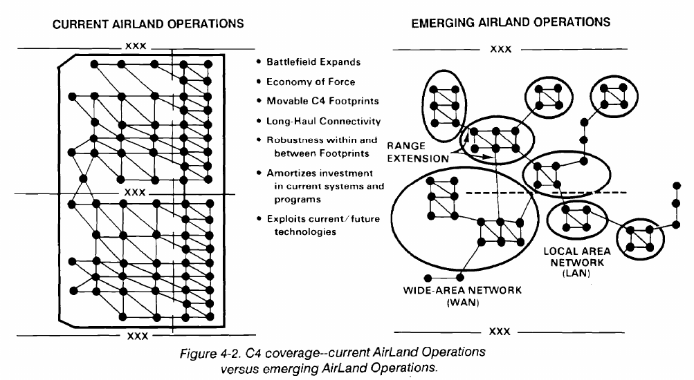
4-10. Corps BSM
kilometers wide by 250 kilometers deep. The
electromagnetic spectrum management of this area
includes the airspace above it. Emerging AirLand
Operations doctrine is changing the corps area from linear
to nonlinear. It will also greatly extend the corps area. (See
Figure 4-2.)
The corps is the Army’s principal force in the theater of
operations. Figure 4-1 shows a typical corps structure. The
make up of the corps varies with mission requirements. It
controls up to five and two-thirds divisions and selected
combat support and combat service support units.
Examples are the military police, military intelligence,
psychological operations, civil affairs, and US Air Force
weather units. The corps can cover an area as large as 140
FM 11-92 covers the specific personnel responsible for
corps BSM. Their titles and general responsibilities are
discussed in the following paragraphs.
4-8
FM 24-2
The corps signal officer (CSO) who is the corps signal
brigade commander is responsible for BSM within the
At corps level, the radio frequency officer/spectrum
management NCO and the radio systems officer serve as
corps. The CSO--
members of the corps G6 staff. They perform the
•
•
•
•
•
•
•
•
Advises the commander of spectrum impacts of
planned combat operations.
Indicates any possible conflicts between
battlefield functions based on spectrum
availability and proposes appropriate solutions.
Ensures the performance of BSM functions.
Advises on all signal matters.
Exercises technical staff supervision over corps
signal activities.
Coordinates frequency assignments and
interference problems.
Assists in preparing EW plans and annexes.
Advises the corps commander on
•
•
•
•
•
•
•
•
•
electromagnetic radiation matters.
The CS0 as the signal brigade commander--
Commands and controls all assigned and
attached signal units.
Performs communications system planning,
engineering, and control functions.
day-to-day BSM functions.
The radio frequency officer/spectrum management
NCO--
Coordinates frequency assignments.
Serves as the point of contact for MIJI and all
ECM operations.
Prepares SOI items pertaining to spectrum
management.
The radio systems officer--
Exercises staff supervision over radio
communications activities.
Prepares SOI items pertaining to radio
communications.
Coordinates with the radio frequency
officer/spectrum management NCO.
Prepares SOIs, plans, and orders for the corps
headquarters, the headquarters of major
subordinate commands, and various ground
liaison nets.
4-9
FM 24-2
Specific BSM staff functions include--
•
•
•
•
•
Allotting/assigning/coordinating frequencies to
subordinate commands.
Coordinating implementation of effective dates of
SOI editions and time period changes to radio
nets of nondivisional corps units.
Maintaining reserve frequencies in all
appropriate bands for contingency, systems
restoration, and antijamming operations.
Coordinating and implementing BSM.
Maintaining a complete and current data base on
spectrum use in the corps area of operations.
At the signal brigade headquarters, the systems
engineer--
•
•
•
•
•
Evaluates radio propagation data for brigade
radio networks.
Assigns frequencies to units in the brigade.
Coordinates RF requirements.
Maintains records, prepares reports, and initiates
correspondence to corps headquarters on
brigade RF matters.
Is responsible for engineering radio
communication systems.
One spectrum management NCO assists the systems
engineer. The CE officer and the radio officer assist the
systems engineer in preparing engineering plans.
The systems engineering staff of the corps signal brigade
S3 is responsible for spectrum management to support the
mobile subscriber equipment (MSE) mission and
engineering its communications systems.
4-11. SOI and Spectrum Management
The SOI is a COMSEC aid and a spectrum management
document. The US Army Communications Electronics
Services Office SOI Detachment at Fort Meade, Maryland
designs SOI based on unit input requirements for central
production at the NSA. FM 24-35 contains instructions on
SOI. Current DA policy limits the centrally-produced SOI
to separate brigades or larger size active Army and Reserve
units, except in cases authorized by Headquarters, DA,
DISC4 through the US Army Communications-
Electronics Services Office. Those units not authorized to
receive the centrally-produced SOI will make a
manually-produced SOI following FM 24-35.
The signal officer at corps, division, and separate
brigades and below are responsible for the unit SOI. The
work sheets for each unit are filled out in accordance with
FM 24-35 and are sent to the NSA. The NSA will enter the
data base from these work sheets into the required format
for the computer programs. The SOI is generated from this
data base, proofread for errors, corrected, regenerated if
necessary, printed, packaged, and shipped by Armed
Forces Courier Service (ARFCOS) or commercial carrier.
It is delivered to the COMSEC account number servicing
the controlling authority for the SOI. Once distributed, it
is protected like all similarly classified material. The SOI
contains call signs, frequencies, suffixes, expanders, and
passwords which change at least once every 24 hours.
Tactical call signs are letter-number-letter
combinations. Units that normally operate together in a net
or nets have last-letter-unique call signs. Once a net is
established, only the last letter of the call sign and a suffix
are used by those units. This reduces transmission time and
makes it more difficult for a threat force to identify a unit.
Suffixes and expanders are used to further identify a user
where confusion could otherwise result. Other SOIs may
be manually produced as required with prior approval of
the controlling authority. Three basic SOI are a training
SOI, an operational/reserve SOI, and an exercise SOI.
A training SOI is used during routine classroom,
garrison, and field training situations for which exercise
SOI are not produced. At least three ten-time period
(30-time period total) SOI editions should be prepared.
These editions are rotated to simulate operational use and
are reused until replaced. Replacement is usually caused
by unit reorganization,
major frequency allocation, or
normal wear and tear.
An operational SOI is used for daily operations. A
reserve SOI is the next time period’s operational SOI. The
term operational/reserve refers to either SOI. However,
the reserve SOI is always the contingency SOI. At least
three ten-time period SOI editions should be prepared by
units preparing manual SOI. Units receiving the centrally
produced SOI are normally provided 180 time periods of
operational/ reserve SOI.
4-10
FM 24-2
An exercise S01 prepared as required is for field
training situations where the training SOI will not suffice.
At least two ten-time period SOI editions should be
prepared to permit supersession/rotation actions as
appropriate. Units receiving the centrally-produced SOI
are normally provided at least 30 time periods (three
editions) of exercise SOI.
The contents of a specific SOI depend on the
requirements of the using command. The signal officer,
who assumes overall managerial responsibilities of the
system for the commander, determines item contents
based on command mission requirements. All SOI contain
standard items with each item following a standard format.
The items are printed in pocket-sized books (4 1/8 by 4 3/4
inches). Each book contains ten time periods (except the
Battlefield Electronic CEOI System (BECS) which has
only five) of changing information.
The centrally-produced SOI is designed to meet the
needs of the using command and item contents may vary
accordingly. Each document normally contains--
•
•
•
•
•
•
An index.
Changing call signs and frequency assignments.
Changing suffixes and expander assignments.
•
•
•
•
Pyrotechnic and smoke signals.
Signs and countersigns.
Supplemental instructions for use of the above
items.
(Nonchanging standard items include medical
evacuation procedures,
net radio interface (NRI),
switchboard designators, and similar SOP items. There are
20 standard items. A unit may select any number of these
items or none.)
The centrally-produced SOI has an organization net list
(ONL) of all nets and their assigned frequencies for each
time period. A sequential frequency list (SFL) is also
produced. It contains all the authorized frequencies used
in that SOI and the nets to which they are assigned for each
time period. These lists may be used to identify and resolve
frequency interference problems.
The corps spectrum manager manages single-channel
and FH tactical combat net radios using the SOI process.
He coordinates and distributes the SOI to corps assigned
units, less the divisions. The signal officer is responsible for
BSM support to all corps units. The SOI contains changing
frequencies, call signs, and suffixes. BSM personnel
manage all radio-related SOI items for corps-based units,
and the frequency resources issued to divisions for
inclusion in each division SOI.
Currently, all active component corps use the NSA’s
centrally-produced SOI. Corps BSM personnel perform a
coordinating function in this automated SOI program. If
corps level units produce the SOI manually, the radio
frequency officer/spectrum management NCO is directly
responsible for implementing the radio-related SOI items
for corps-based units. The radio frequency
officer/spectrum management NCO will furnish guidance
to subordinate commands on frequencies, call signs, and
suffixes to be used within these commands.
Because of the flexible organization of the corps, BSM
techniques used may vary from those at division. Factors
that determine the techniques are--
The corps organization.
The deployment and employment of operating
maneuver forces.
The type of operation in which the corps is
engaged.
The CE systems that support the operation.
The requirements of subordinate divisions, corps
support units, higher headquarters, and units of other
services in the corps area will also influence the
methodology of corps BSM.
The corps spectrum manager delegates spectrum
management authority for multichannel radio equipment
to some units within the corps. These units include the
corps signal brigade, the air defense artillery, and the air
cavalry combat brigade. These particular units are allotted
frequencies for line of sight (LOS) radio systems. In turn,
the signal officers of those units assign frequencies from
their allotments based on system engineering criteria.
There is a requirement to change call signs and
frequencies (HF, 2 to 30 MHz and VHF-FM, 30 to 88
MHz) on tactical radio nets daily. The spectrum manager
allots the frequencies to the divisions and assigns
frequencies for corps troop units. For independent
4-11
FM 24-2
operations by corps elements configured into task force
units, the spectrum manager may choose to issue frequency
allotments if the organizational area of that task
organization will not conflict with the corps main area of
operations.
For special signal equipment and temporary frequency
assignments, the spectrum manager processes requests on
a case-by-case basis. He also maintains locally generated
records of each assignment for future reference. The use
of weapons and special-purpose systems will be
precoordinated with the spectrum manager, inputted into
his data base, and used as required based on the
deconfliction process.
BECS automates and decentralizes SOI production on
the battlefield. It also provides automated spectrum
management data for SINCGARS. BECS generates SOI
data and SINCGARS spectrum management data. This
data is displayed, printed, stored, and electronically loaded
or transferred by SINCGARS radios. The electronic BECS
SOI will eventually replace the NSA’s centrally-produced
paper SOI. The BECS spectrum management data
generates TRANSEC key to meet the unique ECCM
requirements of the SINCGARS HOPPING mode. BECS
is more responsive to rapidly changing and highly mobile
battlefield conditions through SOI decentralization. It is
used as an integral subsystem of SINCGARS, improved
high frequency radio (IHFR), short term antijam (STAJ),
and other VHF (AM/FM), UHF, and HF radio systems.
See FM 11-32 for further details.
4-12. Corps Area Airspace
Air Force and Navy close air support and organic Army
aviation support to the ground commander present a
significant additive inventory to the emitter density within
the corps area of operations. The air-ground operation
system includes the Army air-ground system and the Air
Force tactical air control system. It extends throughout the
major echelons of corps to perform reconnaissance,
surveillance, fire support, and airlift. Extensive
communications support to these elements is essential to
ensure responsive, coordinated use of the corps airspace.
Collocation of these facilities with the echelons of corps
dictates their unique spectrum-dependent
communications be harmonized and integrated among the
competing demands for limited resources.
The corps commander is responsible for coordinating
airspace activities. The spectrum manager is responsible to
the commander for the electromagnetic environment
within that same zone. He must be aware of any air activity
which could interfere with ground maneuver unit
communications. The spectrum manager can advise the
corps commander on possible mutual interference and
reduce any harmful effects on command and control of the
corps. Coordination can increase air activity and ground
actions by preventing interference. Assigned and attached
Army aviation units use corps spectrum resources allotted
to them. Air Force units, using frequencies in the bands
allotted by EAC, require coordination with the corps BSM
staff to avoid possible interference. The airspace
management elements under the G3’s staff supervision and
the corps BSM function as focal points where airspace
requirements can be met, and where airspace frequency
problems can be resolved.
Another source of information for spectrum
coordination is the US Air Force tactical air control center
(TACC). It is responsible for airspace control, ground
tactical sensor surveillance, air support, and air strike
coordination and control. The airspace management
liaison section at the TACC coordinates integrating Army
air traffic control facilities. This coordination involves
integrating flight operations centers, flight coordination
centers, approach/departure control facilities, airfield
control towers, and navigational aids furnished by the
corps air traffic control. Thus, the TACC is another source
of information and liaison for coordinating spectrum
resources used by Army traffic control facilities.
The corps area is divided into a tactical operations area
and a rear operations area.
The dividing line between the
two is defined as the rear boundary of the frontline
divisions. Procedures for airspace control and
coordination within the two areas are defined in terms of
traffic movement and electronic control. The interface
point for integrating the corps and the air forces is the
battle coordination element (BCE) located at the TACC.
The corps representatives in the airspace management
liaison section are members of the BCE. They coordinate
corps requirements to operate aircraft and/or weapon
systems within the airspace over the corps. Therefore,
Army representatives in the TACC help the corps
spectrum manager resolve airspace electromagnctic
spectrum problems.
4-12
FM 24-2
4-13. Corps Air Defense Artillery Operations
Air defense artillery weapons use within the corps is
integrated into the force commander’s scheme of
maneuver. Theater Army air defense artillery units
(brigades and battalions) are normally placed to support
the corps. It may be an Army air defense command,
brigade, or battalion depending on the size of the theater
of operations, the number of air defense artillery battalions
assigned, and the corps commander’s stated requirements.
Nondivisional air defense artillery units in the corps area
(HAWK, PATRIOT, SHORAD) establish internal and
external radio nets, internal multichannel radio systems,
semiautomatic command and control systems, and radar
equipment. Their use must be coordinated with the
spectrum manager. Their CPs are integral parts of the
airspace control system which regulates firing of air
defense weapons and prevents undue interference with
other operations.
The corps spectrum manager
coordinates spectrum resource use and resolves competing
spectrum assignments to minimize mutual interference.
4-14. Military Intelligence Combat Electronic
Warfare and Intelligence
Military intelligence combat electronic warfare and
intelligence (CEWI) units will be deployed throughout the
theater area and will provide assistance in EW,
interference, and jamming. The CEWI staff includes an
EWO who can be consulted on EW matters. Military
intelligence CEWI units supporting the division, corps, or
theater may be requested to identify and locate an
interference source.
Communications is essential to intelligence operations.
With the integration of all intelligence, security, and EW
assets into one unit, the military intelligence CEWI’s
mission dictates using the electromagnetic spectrum, plus
resources for command and control of its own units. Corps
G2, G3, EW, and BSM personnel must closely coordinate
with each other to optimize command and control
communications while effecting EW operations against the
threat force. The basic task for the spectrum manager is to
analyze the impact of proposed IEW operations on
command designated priority command and control
communications. The G3 has final decision authority
should any conflict between the IEW staff and BSM staff
occur.
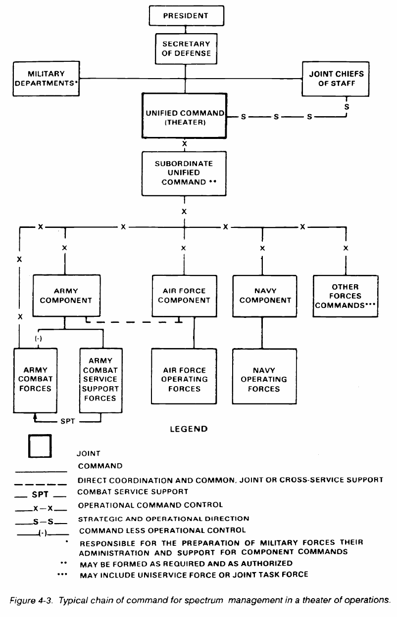
4-15. EAC BSM
EAC command structure is normally that of a US
theater. EAC may include US-only headquarters, theater
Army, a joint task force, and/or a headquarters containing
personnel from more than one nation. Since peacetime
military forward deployments exist, US Army forces must
operate within Allied command relationships to obtain
host nation support which includes spectrum assets. Figure
4-3 shows a typical US national chain of command for a
theater of operations. BSM coordination lines will parallel
these command lines for national spectrum-related
activities.
4-16. Unified Command BSM
In all overseas commands involving large geographic
area and services, a unified command is established for a
theater of operations. The major Army, Navy, and Air
Force headquarters are component commands within the
theater.
Spectrum management for US military forces in an
overseas area is under the control of the highest command
present. In a unified command, the JCS provide policy
guidance, and the overseas commander provides theater
guidance to the component commands. The theater
commander exercises control over electromagnetic
spectrum use within the theater through his joint staff. The
J6 has primary staff responsibility for spectrum
management in the theater. The J6 office includes trained
spectrum management personnel who are responsible for
the allotment and assignment of all frequencies used by
forces within the theater or zone of operations.
In most cases, the theater of operations involves Allied
forces and the unified command in a combined operation.
Moreover, some allies use and manage the spectrum
differently from their US counterparts. Since many
variations exist in providing definitive guidance, it is
essential that US Army spectrum managers realize this and
prepare to adjust to the combat situation. It is also essential
that agreements be made between Allied forces and issued
as early as possible so proper cross attachments between
spectrum managers can be made. Basic guidance is given
below.
4-13
FM 24-2
4-14
FM 24-2
The spectrum management systems techniques and
procedures should allow control over the resources
available in that area of responsibility. The technique
should also provide the flexibility needed to match a
continually changing communications and electronics
environment.
A higher formation is responsible for coordination with
a lower formation/unit. A formation on the left is
responsible for coordinating boundary requirements with
the formation on the right. Frequency requirements of a
supported attached formation/unit will be provided by the
supported formation.
All staff levels of spectrum management will maintain
an accessible database so the signal staffs can execute their
portions of redeployment planning by their commanders.
Equipment characteristics should be registered and
current.
4-17. Theater Army
The theater Army, as the Army component command
of a US unified command, normally exercises command
and/or operational control over all US Army forces in the
theater before the outbreak of hostilities. The theater Army
provides communication services to Army elements and to
other services and agencies, and is responsible for
spectrum management of all subordinate Army
commands. The signal section performs frequency
planning, coordinates frequency use, and publishes
frequency information to subordinate commands. The
signal section also maintains frequency assignment
records, including a master list of frequency and call sign
allocations and assignments for the entire theater Army
area of operations.
At agreed on times during contingency operations,
selected and earmarked theater Army combat, combat
support, and combat service support units will be assigned
to Allied commands. Certain operational arrangements
will be set up based on the designated tactical
commander’s established priorities. Units in the theater
remain under theater Army command until they are
assigned to the operational control of the appropriate
command. These units could be assigned to a corps or they
could be retained by the theater Army. The spectrum
manager must be aware of the signal requirements for
in-theater forces and for forces that may arrive from
CONUS. These forces may augment combat, combat
support, and combat service support units of the corps.
Phase-in of these forces may be a smooth and efficient
process based on existing war plans. However, a phase-in
may be dictated by the present or anticipated combat
situation, resulting in unexpected spectrum requirements
for these additional forces and units.
It is possible that unplanned out-of-theater
reinforcements may be alerted to deploy with minimal
notification. Unit predeployment planning must include
early identification of operational needs and
electromagnetic spectrum requirements to allow the
theater signal office to respond to those needs as soon as
practicable.
The theater Army signal office retains the wartime
spectrum management responsibility for all EAC signal
support. It is responsible for managing spectrum resources
required to support all national administrative and logistic
communications that support each of those corps released
to the operational command of an Allied headquarters.
In the theater Army, EAC spectrum management is
done by the Frequency Management Office, Operations
Division, of the theater Army signal section. This branch is
responsible for summarizing the electromagnetic
requirements of all subordinate commands. The branch
then prepares the frequency allocation lists (FAL) which
are published as the frequency allocation and usage list of
the unified command. Thus, the branch performs
frequency planning, coordinates frequency use, and
publishes frequency information to subordinate
commands. The branch participates in frequency planning
with higher and lower commands and helps to ensure that
the policies and directives of higher commands are being
followed. The branch also maintains frequency allocation
records and a master list of frequency and call signs for
equipment organic to its unit. They also maintain the ability
to acquire rapidly the data they need from lower echelons
regarding frequencies and call signs. Each element and/or
echelon maintains a master list of frequencies and call signs
for equipment organic to its element and/or echelon and/or
area of operation.
4-18. Theater Signal Command (Army)
The Theater Signal Command (TSC) Army (A)
provides command and area communications coverage in
the communications zone (COMMZ), extending
communications from the theater rear boundary where
communications access points are established at area
signal centers. The TSC(A) commander is dual-hatted as
the theater Army signal officer.
In the standard command structure, the TSC(A) ranks
as a major subordinate command of the theater Army. In
turn, the TSC(A) apportions frequencies to other theater
Army subordinate commands for operations of the
TSC(A) managed theater communications systems.
4-15
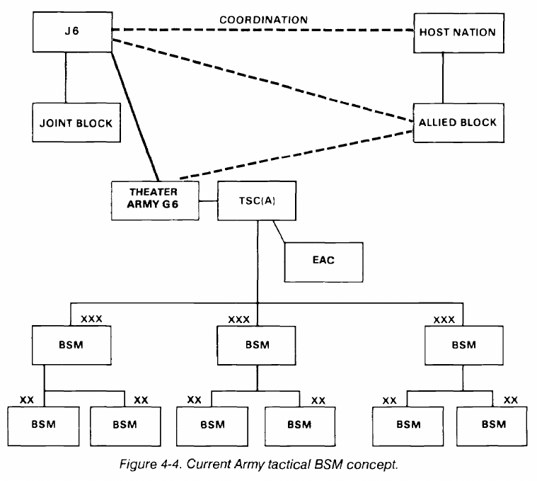
FM 24-2
However, the theater Army commander may direct the
TSC(A) to perform all spectrum management for theater
Army units. That is, TSC(A) would not only apportion
spectrum resources, but also perform direct liaison with
appropriate national authorities in a friendly environment
or act as sovereign spectrum management authority in a
hostile nation.
Higher headquarters and the host nation may impose
spectrum and spectrum-related restrictions on the theater
Army. These restrictions, plus those of the theater Army
commander, will be reflected in the frequency allotments
and assignments to its subordinate commands. Generally,
restrictions are related to the size of the theater Army area
of operations, the requirements of the host nation and
Allied forces, the types and quantities of equipment being
operated, the electromagnetic spectrum available, and the
requirements for strategic communications.
4-19. Automated BSM
The proliferation of C3I equipment and
electromagnetic spectrum requirements, such as during
Operation Desert Shield, often exceed the available
frequency resource. Without automated spectrum
management and engineering capability, compatible BSM
can not happen.
BSM at all echelons of command needs to have
automated tools to efficiently manage their frequency
resource and to provide engineering support.
The capability must exist to allow for electronic transfer
of frequency assignment data between echelons of
command and/or service components.
Current Army tactical BSM, in most cases, still operates
in the MANUAL mode. Operation Desert Shield revealed
weakness in the overall BSM. Those units that had
automated frequency engineering capability were able to
quickly engineer noninterfering systems and were able to
react to the dynamic battlefield. Those units that had no
automated tools could not react as quickly. (See Figure
4-4.)
The proposed concept of automated BSM will allow
echelons of command from division to the TSC(A) to
electronically transfer frequency data between the
echelons and automatically update data bases. (See Figure
4-5.)
4-16
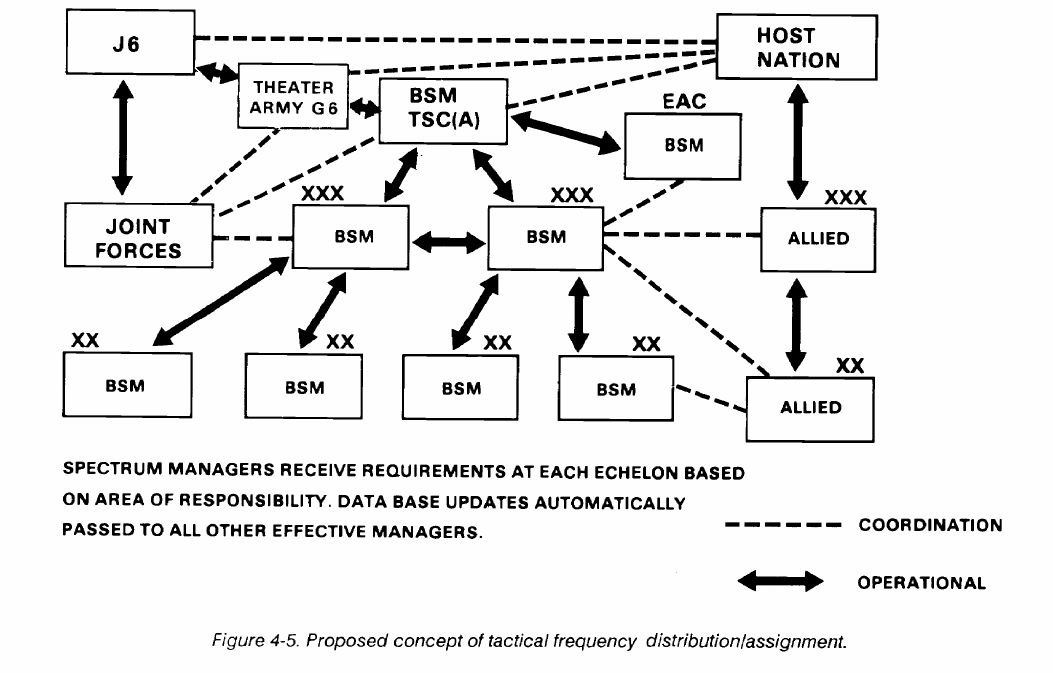
FM 24-2
There are many automated frequency tools currently
fielded or being developed. Some are--
•
•
•
•
•
ATFES - Army Tactical Frequency Engineering
System.
SPEED - Marine Corps System Planning,
Engineering, Evaluation Device.
EMCAS - Electromagnetic Compatibility
Assurance Software.
AFES - Army Frequency Engineering Software.
ISYSCON BSM Module - Integrated Systems
Control Battlefield Spectrum Management. (See
Figure 4-6.)
•
•
•
•
BECS - Battlefield Electronic CEOI System.
MSE SCC - Systems Control Center.
MSE-FURIES - Frequency Utilization
Resources Integrated and Engineering System.
JSMS - Joint Spectrum Management System.
There are many personal computer (PC) based
programs that have been developed to aid the spectrum
manager. These automated tools with an updated database
will enhance overall BSM at any level, especially at division
and corps.
4-17
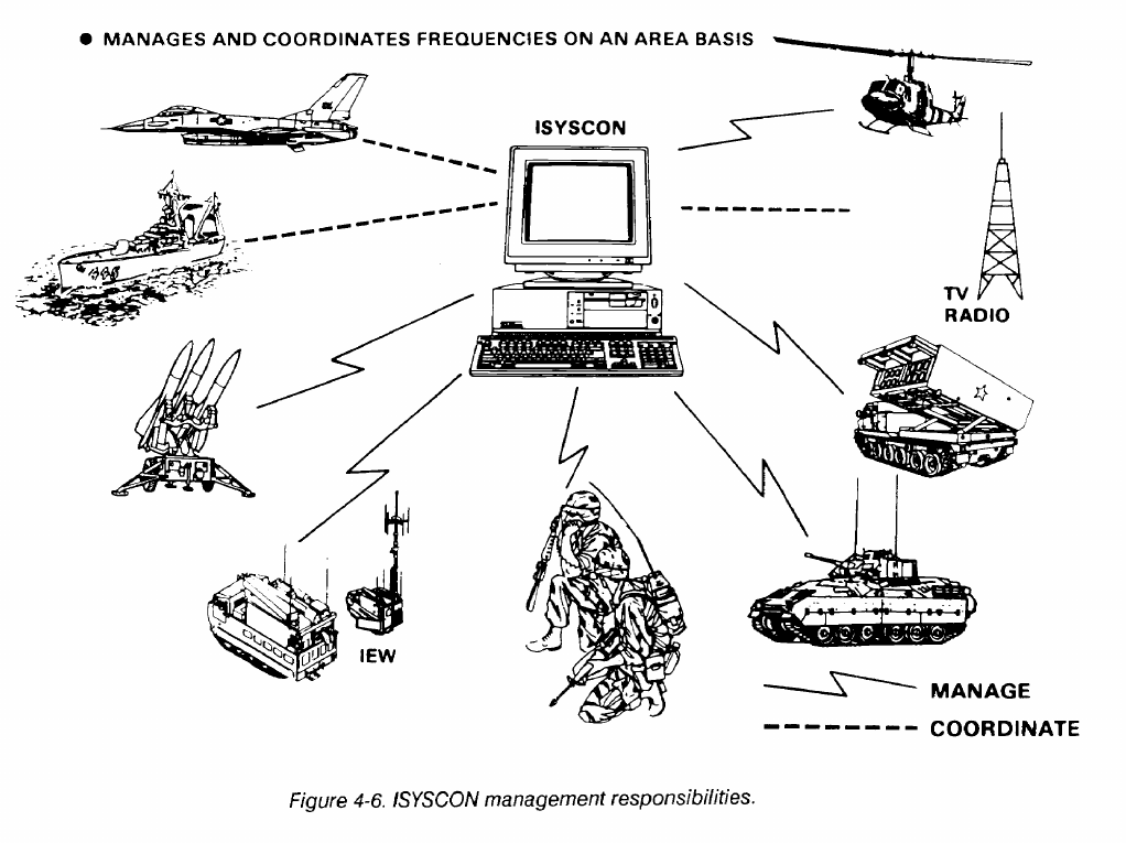
FM 24-2
4-18
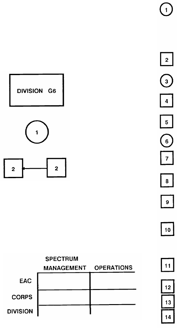
FM 24-2
Appendix A
Baseline BSM Tasks
A-1. Introduction
This appendix presents baseline BSM tasks for frequen-
cy requests and other related responsibilities. These tasks
appear in tabular and functional-flow diagram form. The
procedural steps listed in the following paragraphs are
keyed by number to the associated diagram. These num-
bers indicate relative sequence only some procedures can
be done concurrently.
A legend for the diagram symbology is shown below.
A rectangle identifies the
specific office or the in-
dividual who accomplishes
the associated procedural
steps.
A circle indicates that the
numbered procedural step
is accomplished within the
associated rectangle.
A small square indicates
that the numbered proce-
dural step either outputs to
or receives input from
another rectangle. Arrows
indicate direction of flow.
The frequency request and MIJI diagrams are divided
into two separate functional areas: the left side for
spectrum management and the right side for operations.
The functional areas are further subdivided into echelons
EAC, corps, and division. These subdivisions would also
apply where other echelons (for example, separate
brigade) perform the same procedural steps as division.
A-2. Frequency Request for Tactical
Low-Frequency Beacons
In Figure A-1, the division aviation officer
develops requirements for tactical low-frequency
beacons (LFBs) to support division helipads, for-
ward area rearm/refuel points, pathfinder opera-
tions, and (in coordination with the air traffic
control officer) tactical airfields.
The division aviation officer sends a request to the
division BSM for frequencies and identifiers.
The division BSM checks the request for ac-
curacy, completeness, and validity.
The division BSM sends the request to the corps
BSM.
The corps BSM sends the request to the EAC
BSM.
The EAC BSM coordinates the request.
The EAC BSM sends frequency and identifier
assignments to the corps BSM.
The corps BSM sends the assignments to the
division BSM.
The division BSM sends the assignments to the
division aviation officer and to the division air
traffic control officer.
The air traffic control officer notifies the division
BSM and the division aviation officer when the
tactical airfield beacon has been activated and
checked.
The division aviation officer notifies the corps
aviation officer.
The division BSM notifies the corps BSM.
The corps BSM notifies the EAC BSM.
The corps aviation officer notifies the EAC avia-
tion officer.
A-1
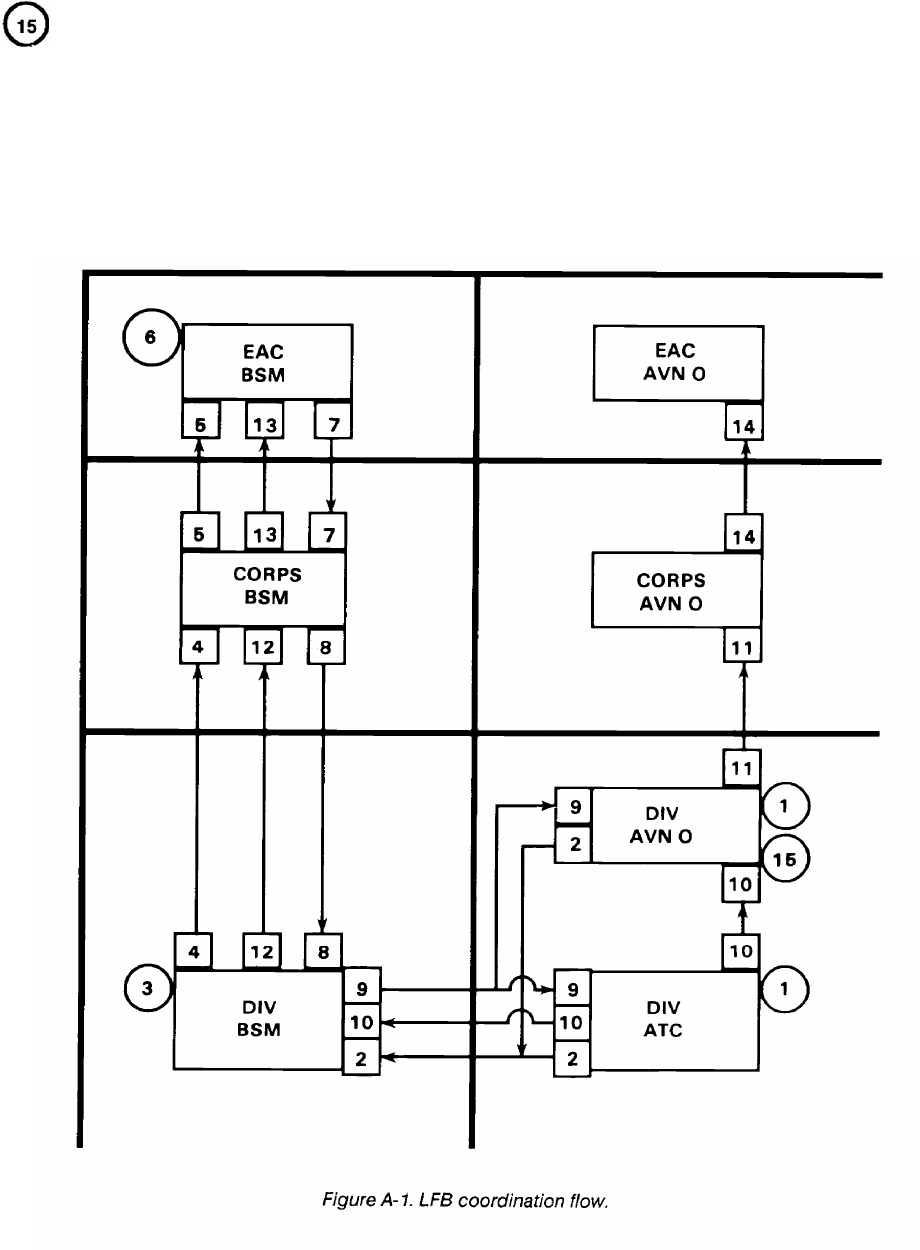
FM 24-2
The other assignments are activated and operated
within the division area of operations on an as
needed basis. In some cases, prior notification is
required.
In addition to its assigned frequency, each beacon has
its own unique identifier (normally three alphabetical char-
acters) which it transmits in Morse code. The unique iden-
tifier distinguishes it from any other friendly beacon that
may be operating in the area.
LFBs at fixed locations remain on the same frequencies
and identifiers indefinitely. In a tactical training environ-
ment, each time the beacon is moved to a new location
another frequency and identifier must be obtained from
the local civil aviation authority. For LFBs, the US Army
uses the AN/TRN-30 which operates in the 200 to 535 kHz
and 1605 to 1750 kHz bands and can output 25 to 180 watts.
A-2
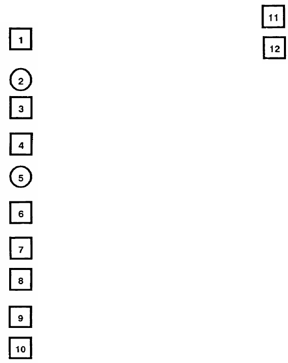
A-3. Frequency Request for Low-Power HF
In Figure A-2, subordinate elements submit HF
frequency requests to the division G6 to support
HF nets.
The division G6 consolidates HF requests.
The division G6 submits the request to the division
BSM.
The division BSM sends the request to the corps
BSM.
The corps BSM checks the corps frequency list to
see if there are frequencies to fill the request.
If so, the corps BSM sends the assignment to the
division BSM.
If not, the corps BSM sends the request to the
EAC BSM.
The EAC BSM sends the assignment to the corps
BSM.
The corps BSM sends the assignment to the
division BSM.
The corps BSM notifies the corps EWO.
FM 24-2
The division BSM sends the assignment to the
division G6.
The division BSM notifies the division EWO.
HF applications within the combat zone normally use
ground wave propagation and relatively low (500 watts or
less) transmitter powers. Distances within the division will
allow coverage by HF ground wave. Groundwave propaga-
tion charts for most areas of the world are available from
the USAISEC. BSM personnel examine these charts with
respect to HF net coverage and link distances. This infor-
mation helps determine the frequencies range that
provides proper coverage. Resources within this range may
then be assigned to applicable nets. Vertically polarized or
specially adapted horizontal antennas are used for ground
wave applications.
High-power HF Defense Communications System
(DCS) links are sometimes used in a battlefield environ-
ment, but requirement generation and frequency coor-
dination are normally done at EAC. HF chirp sounders
(AN/TRQ-35) are used to engineer ground wave and sky
wave systems. This is normally done by the corps or EAC
BSM staff. For more information on chirp sounder opera-
tions, see ACP 191.
A-3
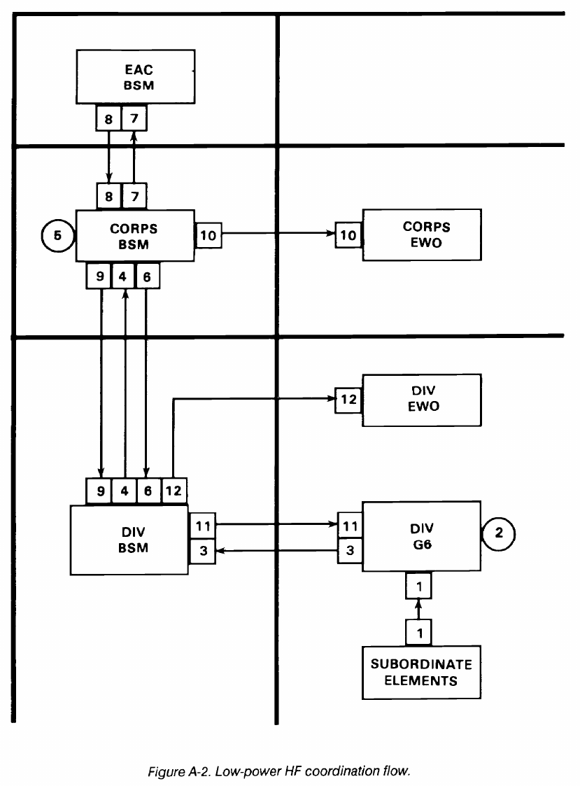
FM 24-2
A-4
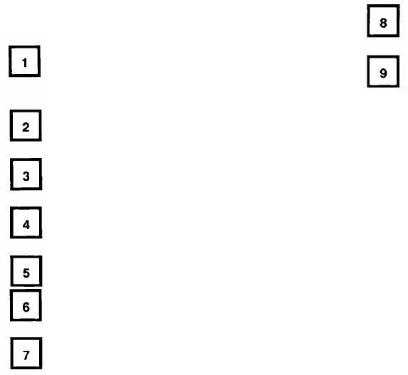
A-4. Frequency Request for VHF-FM
In Figure A-3,
the division G6 submits the re-
quest to the division BSM for VHF-FM frequen-
cies to support the SOI.
The division BSM submits the request to the corps
BSM.
The corps BSM sends the request to the EAC
BSM.
The EAC BSM sends the assignment to the corps
BSM.
The corps BSM notifies the corps EWO.
The corps BSM sends the assignment to the
division BSM.
The division BSM notifies the division EWO.
FM 24-2
The division BSM sends the assignment to the
division G6.
The division G6 makes up the VHF-FM list and
submits it to the SOI Detachment/NSA for the
VHF-FM portion of the SOI.
VHF-FM spectrum resources support combat net radio
operations and MSE. Since the direction and coordination
of real-time combat operations requires that every
battlefield element be equipped with combat net radios,
this frequency band is quite crowded. Corps combat net
radio net requirements exceed spectrum availability for
dedicated frequencies to support every net. Frequencies
are reused or shared many times in the corps area. This
sharing scheme is a major consideration of the BSM staff,
and it is used as the basis for estimating requirements.
The frequency range of VHF-FM combat net radio
equipment is 30 to 88 MHz. It has output powers ranging
up to 50 watts depending on the transmitter used.
A-5
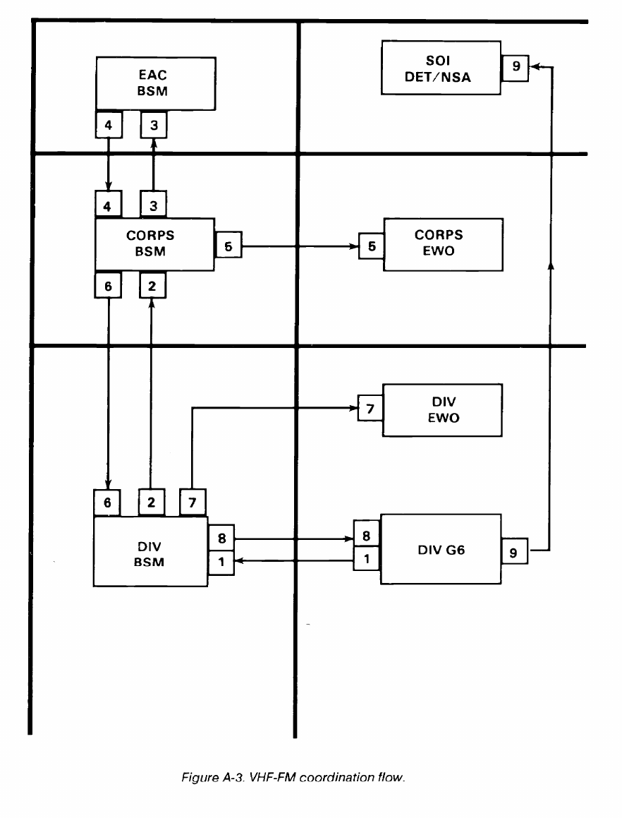
FM 24-2
A-6
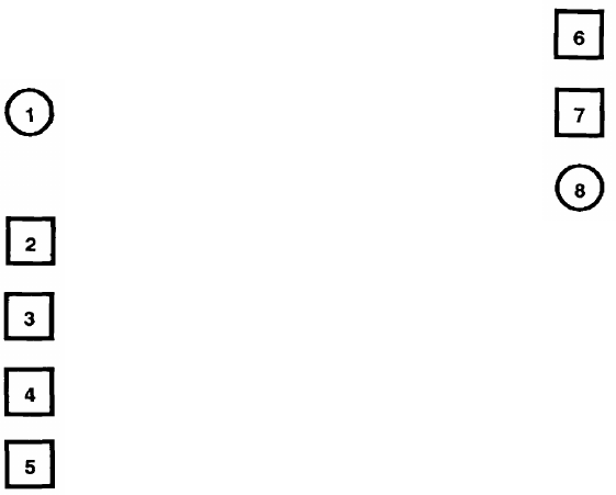
FM 24-2
A-5. Frequency Request for Platoon Early
Warning Sensors
In Figure A-4, the division G6 determines the
number of platoon early warning sensors (PEWS)
based on TOE, TDA, or MTOE operational re-
quirements.
The division G6 submits the request to the division
BSM.
The division BSM sends the request to the corps
BSM.
The corps BSM sends the request to the EAC
BSM.
The corps BSM sends the allotment to the division
BSM.
The division BSM sends the allotment to the
division G6.
The division G6 sends the allotment to the
maneuver battalions operating the PEWS.
PEWS are lightweight, battery-operated, portable
intrusion detection devices. Small military units (patrols,
squads, or platoons) use these devices. On detection, the
device electronically classifies the intruder (personnel or
vehicle) and communicates the detection and target type
to a remote receiver display by a radio link. Several
different sensor models are available. Each model operates
on a fixed frequency in the 138 to 153 MHz range.
The EAC BSM sends the allotment to the corps
BSM.
A-7
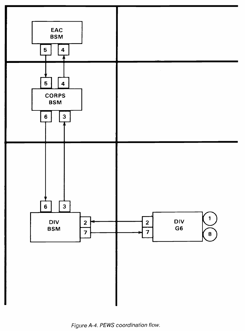
FM 24-2
A-8
FM 24-2
A-6. Frequency Request for VHF-AM
In Figure A-5, the division G6 submits the request
to the division BSM for VHF-AM frequencies to
support division aviation and air traffic control
nets in the SOI.
The division BSM sends the request to the corps
BSM.
The corps BSM sends the request to the EAC
BSM.
The EAC BSM sends the assignment to the corps
BSM.
The corps BSM notifies the corps EWO.
The corps BSM notifies the corps aviation officer.
The corps BSM sends the assignment to the
division BSM.
The division BSM notifies the division EWO.
The division BSM notifies the division aviation
officer.
The division BSM sends the assignment to the
division G6.
The division G6 makes up the VHF-AM frequen-
cy list and submits it to the SOI Detachment/NSA
for VHF-AM portion of the SOI.
The VHF-AM frequency band for military applications
is 118 to 150 MHz. Small segments are allocated for
exclusive military use in some countries, but most of this
band is allocated to the aeronautical mobile R service. The
R denotes route which implies that the band is used for
communications with aircraft flying established air routes.
Most governments consider R bands for communicating
with civil aircraft. (Bands designated OR, for off-route, are
generally limited to military use.) The R band frequency
resources are normally controlled by the civil aviation
authority in each country (FAA in the US).
Although Army air traffic control and aviation
operations are usually conducted on VHF-FM or
UHF-AM frequencies, a requirement exists for VHF-AM.
Civil aircraft sometimes need to contact Army air traffic
control facilities, and occasionally military aircraft are
equipped with only VHF-AM radios. Additionally,
VHF-AM provides a degree of redundance should
VHF-FM or UHF-AM systems fail.
A-9
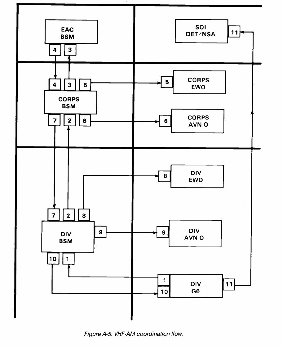
FM 24-2
A-10
FM 24-2
A-7. Frequency Request for UHF Air/Ground/Air
Operations
In Figure A-6, the division G6 submits the request
to division BSM for UHF frequencies to support
division aviation and air traffic control nets in the
SOI. These nets are listed on the net work sheets
submitted by the aviation and air traffic control
elements.
The division BSM sends the request to the corps
BSM.
The corps BSM sends the request to the EAC
BSM.
The EAC BSM sends the assignment to the corps
BSM.
The corps BSM notifies the corps EWO.
The corps BSM notifies the corps aviation officer.
The corps BSM sends the assignments to the
division BSM.
The division BSM notifies the division EWO.
The division BSM notifies the division aviation
officer.
The division BSM sends the assignment to the
division G6.
The division G6 makes up the UHF frequency list
and submits it to the SOI Detachment/NSA for the
UHF portion of the SOI.
In most of the free world, the 225 to 400 MHz band is
allocated for military use (mainly for air/ground/air com-
munications). The same frequency band is used for multi-
channel requirements in Army tactical units although
multichannel and air/ground/air communications are not
conducted on the same frequencies. Most of the free world
has raster or channel allotment plans for this band. It
designates frequencies used for air/ground/air, multichan-
nel, and other telecommunications functions.
The Army is not the sole user of the air/ground/air 225
to 400 MHz frequencies in the combat zone other services
use the air/ground /air frequencies for supplying close air
support. Those agencies inform the supported Army force
of the frequcncies used so they can be inserted into the SOI.
A-11
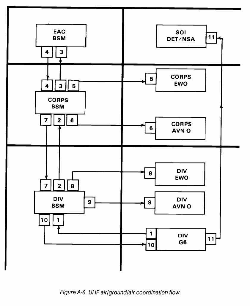
FM 24-2
A-12

A-8. Frequency Request for Division MSE LOS
Systems
In Figure A-7, the division signal battalion deter-
mines how many frequencies are required to sup-
port the division multichannel plan.
The signal battalion requests frequencies from the
division BSM.
The division BSM checks the request for accuracy
and validity.
If the division BSM does not have authority to allot
multichannel frequencies, then the request is for-
warded to the corps BSM.
The corps BSM allots frequencies to the division
BSM.
The corps BSM notifies the corps EWO of the
allotment.
The division BSM receives the allotment and
notifies the division EWO.
The division BSM sends allotment to the signal
battalion.
The signal battalion assigns frequencies as re-
quired to engineered systems.
FM 24-2
In MSE LOS systems, the number of channels per link
ranges from 8 to 64. The high capacity of MSE systems
allows them to meet large volume demands for command
and control, fire control, intelligence, and administrative
traffic.
For MSE LOS purposes, the frequency spectrum is
separated into three bands. Two are UHF, band 1, 225 to
400 MHz and band 3, 1350 to 1850 MHz support the
internodal extension link, using the AN/GRC-226 radio.
To support the shorter SHF down-the-hill (DTH) link, the
AN/GRC-224(P) radio uses SHF band 2, 14.5 to 15.35
GHz.
Antennas used in multichannel systems are highly direc-
tional. For this reason, relatively low powers (15 to 35
watts) are the rule. In comparison, troposcatter systems
typically use 1 kilowatt of power because of the high signal
attenuation in the troposphere.
It is common to have transmitter and receiver antennas
in close proximity. Also, two or more multichannel links
may terminate at the same site. For these reasons, frequen-
cy separation between transmit and receive frequencies of
the same link and frequency separation between different
links are critical. Separation criteria vary with the type of
equipment used.
The MSE links take some time to establish. MSE LOS
frequencies are not included in the SOI frequency chang-
ing program. With each frequency change, the LOS link
has to be reestablished. The time involved in the operation
makes the MSE LOS system a poor candidate for a peri-
odic frequency changing program.
A-13
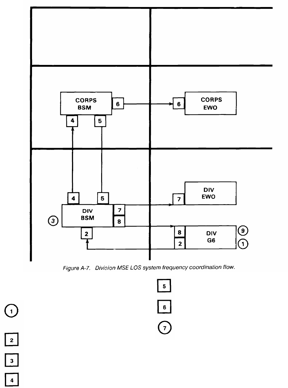
FM 24-2
A-9. Frequency Request for Corps MSE LOS
The corps BSM
ment.
Systems
In Figure A-8, the corps signal brigade radio of-
ficer determines how many frequencies are re-
quired to support the corps MSE LOS systems.
The signal brigade requests frequencies from the
corps BSM.
The corps BSM requests frequencies from the
EAC BSM.
The EAC BSM allots frequencies to the corps
BSM.
The corps BSM
brigade.
notifies the corps EWO of allot-
sends the allotment to the signal
The corps signal brigade assigns the frequencies
to engineered systems as required.
The corps BSM normally has an allotment of
frequencies available which satisfy multichannel spectrum
requirements for corps and subordinate units. The
Spectrum Management Office of the TSC(A) overseas and
the post, camp, station in CONUS provide this allotment.
A-14
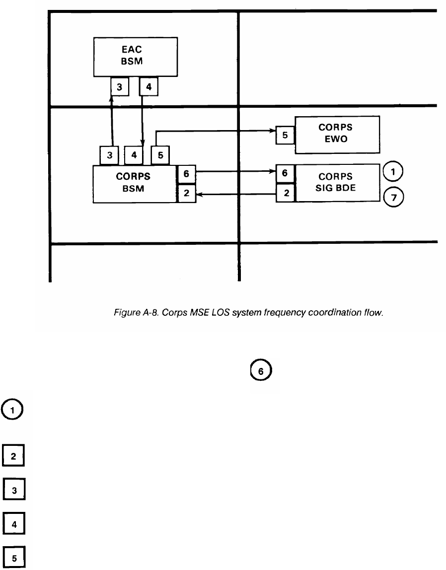
FM 24-2
A-10. Frequency Request for Meteorological
Sondes
In Figure A-9, the corps artillery officer deter-
mines the number of meteorological units within
the corps area of operation.
The artillery officer sends a request for frequency
support to the corps BSM.
The corps BSM sends the request to the EAC
BSM.
The EAC BSM sends the allotment to the corps
BSM.
The corps BSM sends the allotment to the corps
artillery officer.
The corps artillery officer gives the authorization
to the units operating the equipment.
Meteorological sondes (METSONDES) are
balloon-borne equipments which measure atmospheric
pressure, temperature,
humidity, wind speed, and wind
direction in the atmosphere. This data is used primarily to
support artillery operations within the corps area.
The US Army presently uses METSONDES which
operate in the 1660 to 1700 MHz range. Atmospheric
soundings are taken at various altitudes and the data is
transmitted to a ground tracking station which receives,
records, processes, and disseminates the information to
users.
A-15
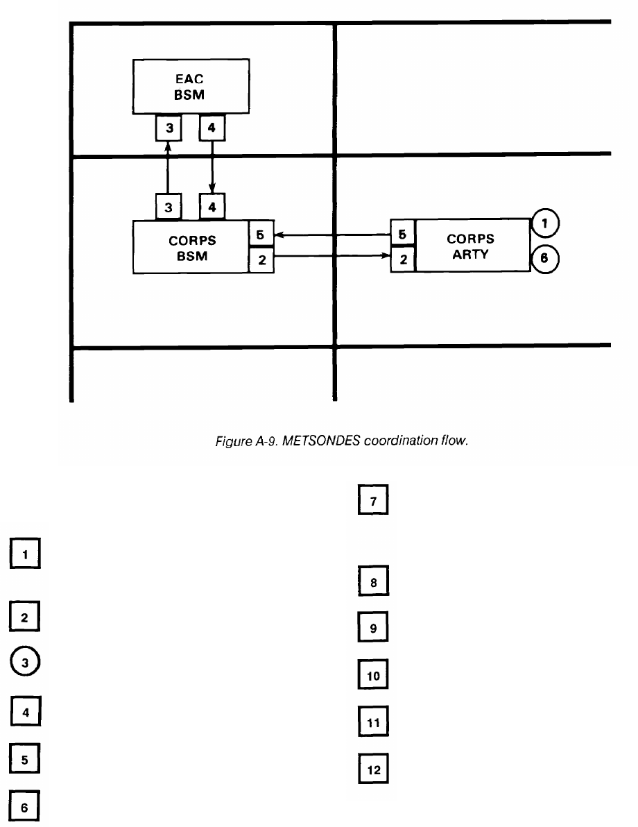
FM 24-2
A-11. Frequency Request for Ground Mobile
Forces Satellite (7 to 8 GHz)
In Figure A-10, the division G3 and division G6
develop requirements for satellite communica-
tions.
The division G6 sends the satellite access request
to the division BSM.
The division BSM checks the request for accuracy
and validity.
The division BSM sends the request to corps
BSM.
The corps BSM sends the satellite access request
to the EAC BSM.
The EAC BSM sends the request to the ground
mobile forces (GMF) satellite communication
control subsystem (SCCS) manager for the
The GMF manager sends the up link and downlink
frequencies and other pertinent information to
the EAC BSM for clearance/approval and dis-
semination.
The EAC BSM sends the assignment to the corps
BSM.
The corps BSM coordinates the assignment with
the corps EWO.
The corps BSM sends the assignment to the
division BSM.
The division BSM coordinates the assignment
with the division EWO.
The division BSM sends the assignment to the
division G6 for distribution to the ground forces
satellite operators.
defense communications area.
A-16
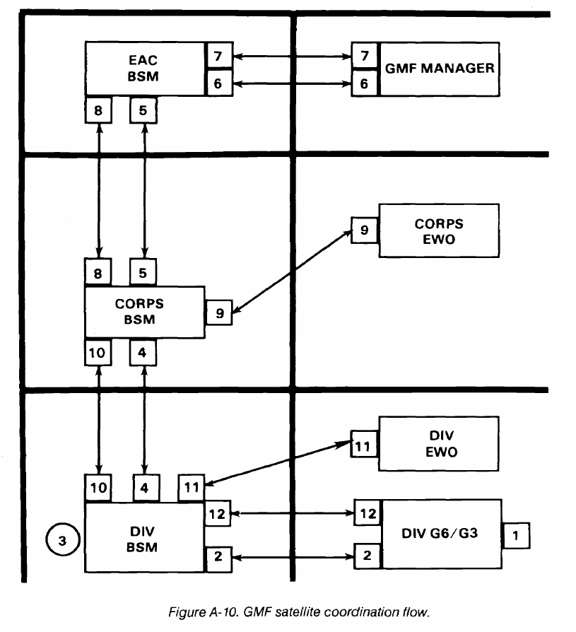
FM 24-2
The SHF transportable GMF terminals provide
multichannel communications at brigade, division, corps,
and the COMMZ to support command multichannel
requirements. The terminals operate with Defense
Satellite Communications System (DSCS) satellites
positioned in geosynchronous orbit over the equator above
the Pacific, Atlantic, and Indian Oceans. Figure A-11
shows the SHF and UHF satellites and terminals.
Procedures for obtaining GMF satellite terminal
authorizations are unique in that two separate and distinct
approvals must be obtained before starting operations. The
GMF manager grants an approved uplink and downlink
frequency; however, these frequencies must be cleared
through normal frequency management channels. The
corps BSM ensures that frequency and satellite access
approval has been received before notifying subordinate
elements. See FM 24-11 for further information.
A-17
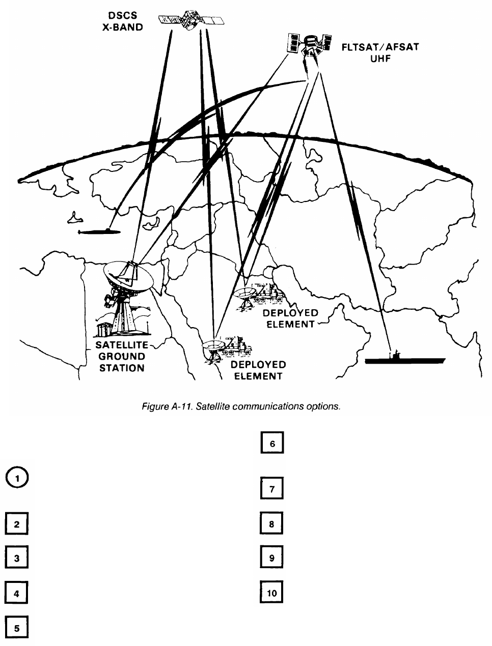
FM 24-2
A-12. Frequency Request for UHF Single-Channel
Satellite Terminal
In Figure A-12, the division G3 and division G6
develop the requirements for using a single-chan-
nel satellite net.
The division G6 sends the request to the division
BSM.
The division BSM sends the request for channel
access to the corps BSM.
The corps BSM sends the request to the EAC
BSM for channel access and frequency approval.
The EAC BSM sends the request for channel
access to the appropriate satellite primary control
center (PCC).
The satellite PCC sends the uplink and downlink
frequencies and any other pertinent information
to the EAC BSM for approval and dissemination.
The EAC BSM sends the approved uplink and
downlink frequencies to the corps BSM.
The corps BSM coordinates the assignment with
the corps EWO.
The corps BSM sends the assignment to the
division BSM.
The division BSM coordinates the assignment
with the division EWO.
A-18

FM 24-2
The division BSM sends the assignment to the
division G6.
The division G6 sends the assignment to the sup-
ported units.
The UHF single-channel satellite service shares the 225
to 400 MHz band with air/ground and multichannel ser-
vices, among others. While multichannel and air/ground
allotted channels occasionally share a channel with another
service, it is rare that a channel designated for single-chan-
nel satellite has an allotment for any other service.
Most single-channel satellite terminals have the
capability of a single voice channel. Some of the newer
terminals have a speech plus capability, that is, one voice
channel plus one teletype (low speed) channel. Normally,
only high-priority command and control circuits are routed
over single-channel satellite facilities.
Like multichannel satellite terminals, two distinct
separate approvals must be obtained. First, the PCC
provides the satellite access uplink and downlink frequen-
cies; however, these frequencies must be cleared through
normal frequency management channels. Requests for
satellite access are sent to the PCC which controls the
satellite in the desired area of operations. In CONUS,
corps or division spectrum managers can request satellite
access from the appropriate PCC. In Europe, it is almost
always an EAC spectrum manager function to 5th Signal
Command. See FM 24-11 for further information.
A-19

FM 24-2
A-13. Frequency Request for Air Traffic Control
Radar
In Figure A-13, the air traffic control officer deter-
mines the location of the air traffic control radar.
The air traffic control officer requests frequencies
for radar and IFF from the division BSM.
The division BSM sends the request to the corps
BSM.
The corps BSM sends the request to the EAC
BSM.
The EAC BSM sends the assignment to the corps
BSM.
The corps BSM sends the assignment to the
division BSM.
The corps BSM notifies the corps EWO.
The division BSM sends the assignment to the air
traffic control officer.
The division BSM notifies the division EWO.
A-20
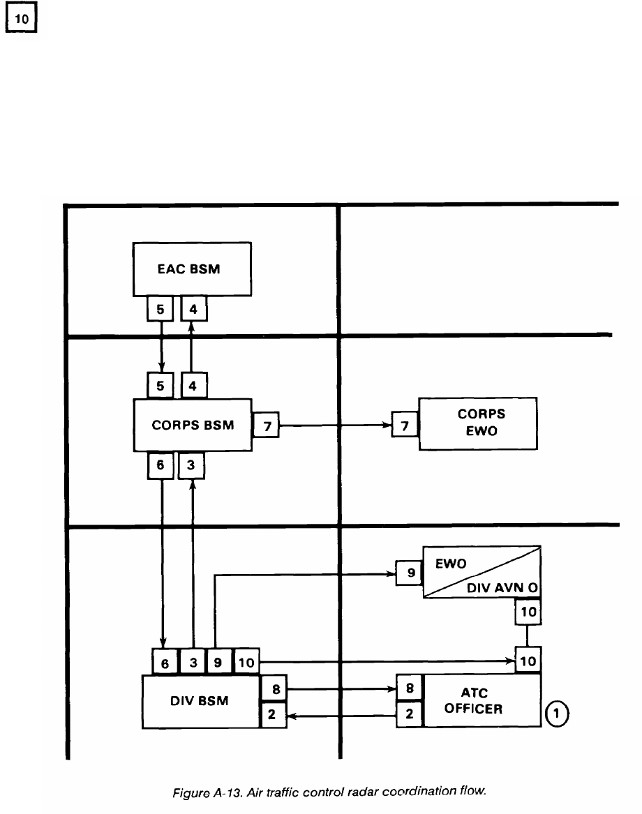
FM 24-2
The air traffic control officer notifies the division
aviation officer and division BSM when radar and
IFF are checked and operational.
Air traffic control radar provides radar approach
control and precision approach radar for aircraft during
adverse weather conditions and high density aircraft
operations. The AN/TPN-18 is used for primary radar and
the AN/TPX-44 is used for secondary or IFF radar. The
two equipments work together. Primary and IFF returns
are adjacently displayed on the same scope. The two
equipments are normally integral parts of an AN/TSQ-71A
landing control central configuration. The AN/TPN-18
operates in the 9.0 to 9.6 GHz band while the AN/TPX-44
operates in the 990 to 1040 MHz band.
Within CONUS, short-term frequency assignments can
sometimes be obtained from the supporting Army
frequency coordinator’s office, thus avoiding
time-consuming frequency clearance procedures at the
national agency level.
A-21
FM 24-2
A-14. Frequency Request for Forward Area Alerting
Radar
In Figure A-14, the air defense artillery sends the
request for frequency support (maximum of six
channels) of forward area alerting radar to the
division G6.
The division G6 sends the request to the division
BSM.
The division BSM sends the request to the corps
BSM.
The corps BSM sends the request to the EAC
BSM.
The EAC BSM sends the assignment to the corps
BSM.
The corps BSM notifies the corps EWO.
The corps BSM sends the assignment to the
division BSM.
The division BSM notifies the division EWO.
The division BSM sends the assignment to the
division G6.
The division G6 sends the assignment to the air
defense artillery battalion.
The air defense artillery battalion assigns chan-
nels to individual radars according to the SOP.
The forward area alerting radar system consists of an
acquisition radar, an IFF for initial identification, and an
RF data link to transmit data to a target alert data display
set to support SHORAD weapons (for example,
CHAPARRAL, VULCAN, and REDEYE). The
AN/TPQ-32 or AN/MPQ-49 is used when equipment is
vehicle mounted (tuning range is classified). The air
defense artillery battalion requests frequencies for the
radar and IFF from the division BSM. Frequencies to
support the data links are found in the division SOI.
A-22
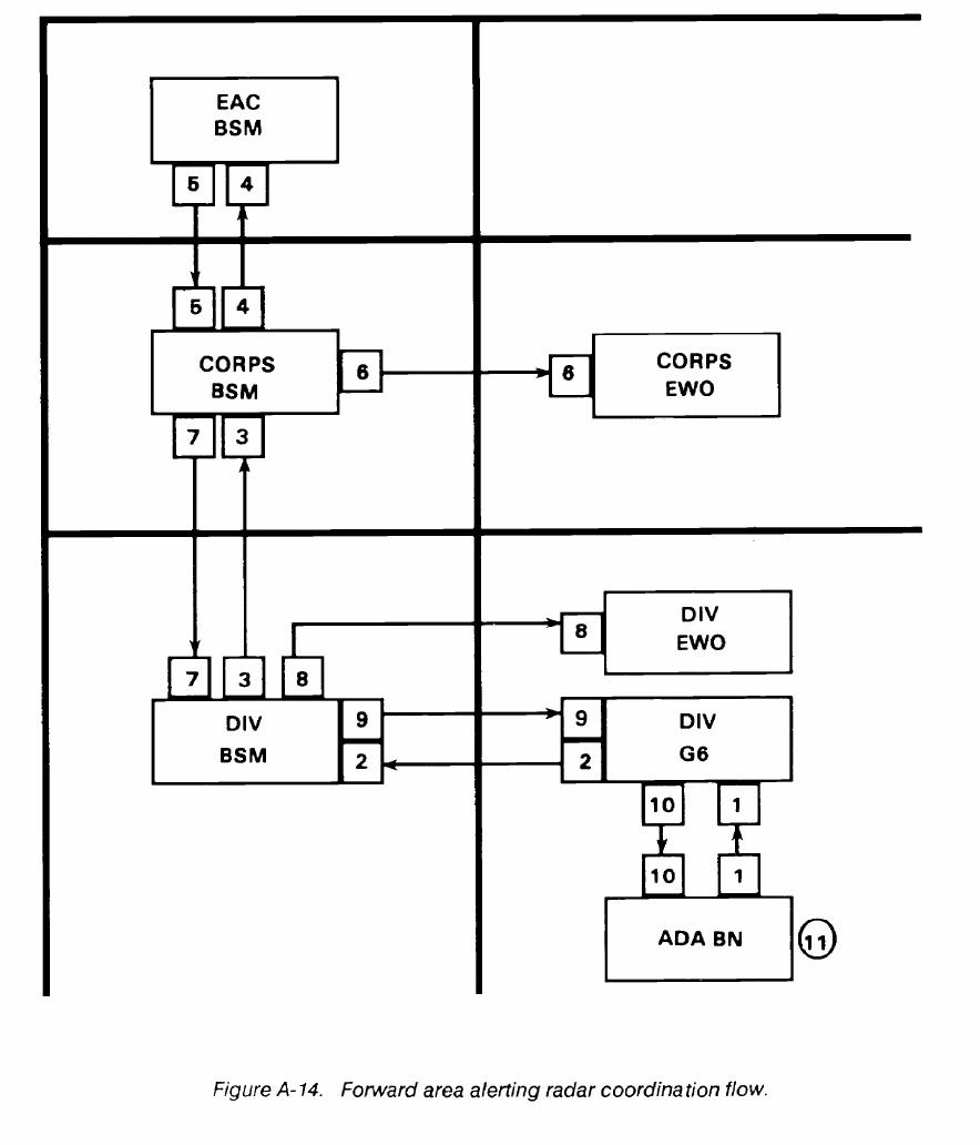
FM 24-2
A-23
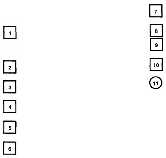
FM 24-2
A-15. Frequency Request for VULCAN Radar
(AN/VPS-2)
In Figure A-15, the air defense artillery battalion
sends a request for frequencies and a pulse repeti-
tion frequency (PRF) to support CHAPAR-
RAL/VULCAN operations to the division G6.
BSM.
The division G6 sends the request to the division
The division BSM sends the request to corps
BSM.
The corps BSM sends the request to the EAC
BSM.
The range-only-radar, AN/VPS-2, is part of the VUL-
The EAC BSM sends the assignment to the corps
BSM.
The corps BSM notifies the corps EWO.
The corps BSM
division BSM.
The division BSM
sends the assignment to the
notifies the division EWO.
The division BSM sends the assignment to the
division G6.
The division G6 sends the assignment to the air
defense artillery battalion.
The air defense artillery assigns frequencies to
individual radars.
CAN air defense system and is used in the fire control
system for antiaircraft artillery guns against low-flying sub-
sonic tactical aircraft. The radar can track aircraft moving
at range rates between 10 and 310 meters per second to a
maximum range of 5,000 meters. The radar operates in the
9150 to 9250 MHz range with a peak power of 1.5 kilowatts.
The entire tuning range is allotted.
A-24
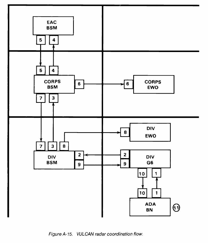
FM 24-2
A-25
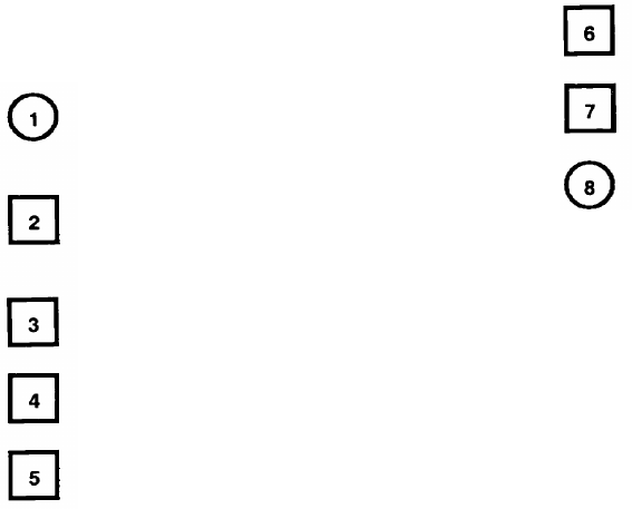
FM 24-2
A-16. Frequency Request for Moving Target
Locating Radar
A-26
In Figure A-16, the requirement for moving target
locating radar is developed at the CEWI battalion
and the target acquisition battery.
The CEWI battalion and target acquisition bat-
tery send the frequency request to the division
BSM.
The division BSM sends the request to the corps
BSM.
The corps BSM sends the request to the EAC
BSM.
The EAC BSM sends the allotment to the corps
BSM.
The corps BSM sends the allotment to the division
BSM.
The division BSM sends the allotment to the
CEWI battalion and the target acquisition battery.
The CEWI battalion and target acquisition bat-
tery send the allotment to the ground surveillance
radar (GSR) platoon and GSR section.
The ground surveillance company of the division CEWI
battalion and the target acquisition battery operate the
moving target locating radar.
The moving target locating radar is deployed near the
FLOT and detects moving targets (vehicles and
personnel). Equipments used are the AN/TPS-25 and
AN/TPS-58. Frequencies are allotted for the frequency
range of the equipment (9400 to 9600 MHz).

FM 24-2
A-27
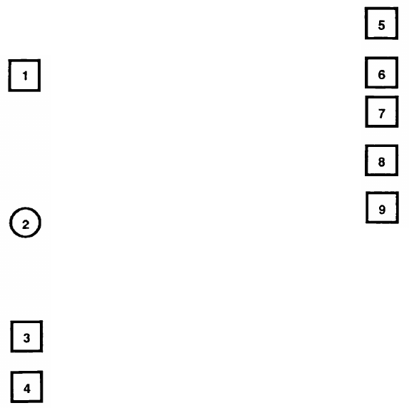
FM 24-2
A-17. Frequency Request for Counter Mortar and
Counter Battery
A-28
In Figure A-17, the requirement at division for
counter mortar and counter battery is based on
TOE and MTOE allowances on hand or planned
to be on hand. Requests for frequency support are
sent to the division G6 by the target acquisition
battery for counter mortar and counter battery.
Equipments used are the AN/TPQ-36, AN/TPQ-
37, and AN/MPQ-4.
Requests for frequency support are received by
the division BSM and checked for validity and
accuracy. The division artillery signal officer iden-
tifies requirements to the division BSM. (This
includes cross attached corps artillery assets con-
trolled by division artillery.)
The division BSM sends the request to the corps
BSM.
The corps BSM sends the request to EAC BSM.
The EAC BSM sends the frequency assignments
to the corps BSM.
The corps BSM notifies the corps EWO.
The corps BSM sends the assignments to the
division BSM.
The division BSM sends the assignments to the
requesting elements.
The division BSM notifies the division EWO.
Counter mortar and counter battery radars are usually
located along the FLOT looking toward the enemy. The
radar locates cannons, mortars, and rockets by detecting
the position of the in-flight projectile at two points in space
and extrapolating this trajectory to its point of origin. The
radar is usually turned off when enemy mortar and artillery
fire is not occurring to reduce its vulnerability to direction
finding. Frequencies are normally allotted for the frequen-
cy range of the radar.
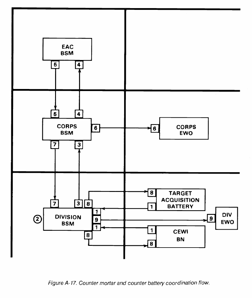
FM 24-2
A-29
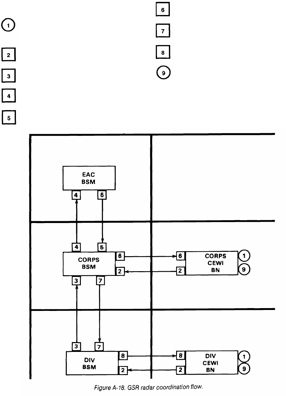
FM 24-2
A-18. Frequency Request for GSR
battalion.
In Figure A-18, the requirements for GSR are
developed by division/corps G2 and the CEWI
The division/corps CEWI battalion sends the fre-
quency request to the division/corps BSM.
The division BSM sends the request to the corps
BSM.
The corps BSM sends the request to the EAC
BSM.
The EAC BSM sends the allotment to the corps
BSM.
The corps BSM sends the allotment to the corps
CEWI battalion.
The corps BSM sends the allotment to the division
BSM.
The division BSM sends the allotment to the
division CEWI battalion.
The CEWI battalion sends the allotment to the
GSR platoons.
GSR is operated at division level by the division CEWI
battalion. At corps and separate brigades, the military
intelligence group provides support. Frequencies are al-
lotted for the entire tuning range.
A-30
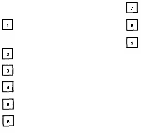
FM 24-2
A-19. Frequency Request for SINCGARS (VHF-FM
FH)
In Figure A-19, the division G6 submits the
division FH net list to the division BSM for VHF-
FM frequencies to support the division combat
net radio FH nets.
The division BSM submits the request to the corps
BSM.
The corps BSM sends the request to the EAC
BSM.
The EAC BSM sends the assignments and lockout
information the corps BSM.
The corps BSM coordinates frequency assign-
ment information with the corps EWO.
The corps BSM sends frequency assignments, fre-
quency lockouts, and net IDs to the division BSM
by fill device/disk, if applicable.
The division BSM coordinates frequency assign-
ment information with the division EWO.
The division BSM sends frequency assignments,
frequency lockouts, and net IDs to the division G6.
The division G6 performs SINCGARS SOI
generation and distributes the SOI to all subor-
dinate units by fill device/disk.
VHF-FM spectrum resources (30 to 88 MHz) along
with the decentralized automated support system (BECS)
is required to support effective SINCGARS operation on
the battlefield. The BECS generates, manipulates, prints,
stores, displays, and transfers the information required to
operate the SINCGARS in the FH/SINGLE-CHANNEL
mode. A hopset is a given number of frequencies which the
SINCGARS can hop or transmit. A hopset can be any
number of frequencies from 1 to 2320. As with single-chan-
nel radio operation, certain civilian radio services continue
to be factors in obtaining and distributing frequency
resources. Frequencies used for these services continue to
be protected from interference by SINCGARS.
A-31
FM 24-2
A-20. Request for ECM Jamming Authorization
The corps BSM sends the request to the EAC
.
In Figure A-20, the CEWI battalion develops the
ECM plan to include the list of frequencies to be
jammed and the point of contact information.
The CEWI battalion sends the request to the
division BSM.
The division BSM sends the request to the corps
BSM.
BSM.
The EAC BSM sends the authorization for jam-
ming, frequencies cleared for jamming, and any
restrictions to the corps BSM.
The corps BSM sends the authorization to the
division BSM.
The division BSM sends authorization to the
CEWI battalion.
A-32

FM 24-2
A-33
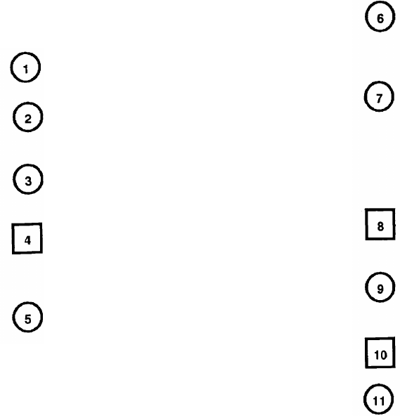
FM 24-2
A-21. MIJI - Part I. Meaconing, Intrusion, and
Jamming
A-34
In Figure A-21, the operator detects abnormal
operation of the receiving equipment.
The operator checks the equipment to ensure that
the abnormal operation is not being caused by an
equipment malfunction.
The operator checks with adjacent units to deter-
mine if that is the source of the problem.
If the operator determines that the abnormal
operation is caused by an outside source, the
operator initiates a MIJI report and sends it to the
BSM.
The division BSM and division EWO evaluate the
MIJI report to determine whether the problem is
caused by friendly or unfriendly sources. The
corps BSM and EWO and the EAC BSM and
EWO may also evaluate the report depending on
what level the report is initiated.
If the source is determined to be unfriendly, the
EWO will attempt to locate it, identify it, and if
determined to be a serious threat, target it for
destruction or neutralize its effect.
The BSM, with command guidance and in coor-
dination with the EWO, will require the equip-
ment to continue operating to conceal that MIJ is
affecting its operation. The BSM may assign alter-
nate frequencies to allow the affected unit to
operate a second piece of equipment so the mis-
sion can continue.
If the source cannot be determined, a follow-up
MIJI report is sent with all available information
to the JEWC and other addressees as required.
The JEWC will enter the information into the data
base and attempt to determine the source of the
problem.
The JEWC notifies the reporting unit and other
addressees of its findings.
The appropriate units take any remaining resolu-
tion actions.
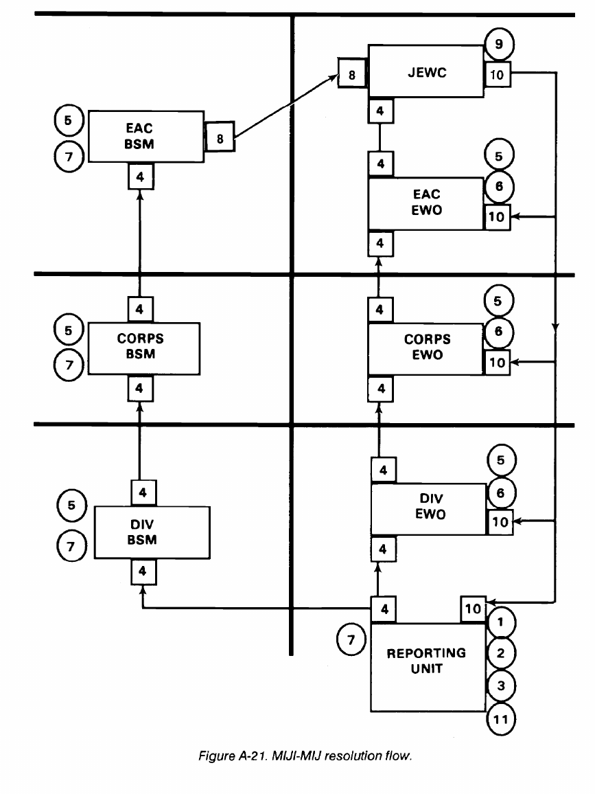
FM 24-2
A-35
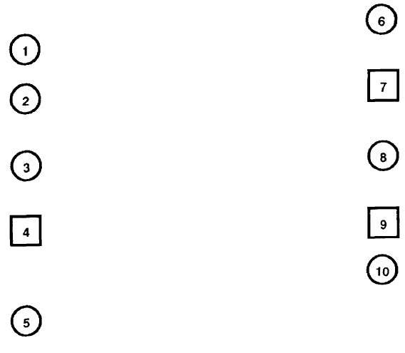
FM 24-2
A-22.
MIJI - Part II. Interference
In Figure A-22, the operator detects abnormal
operation of the receiving equipment.
The operator checks the equipment to ensure that
the abnormal operation is not being caused by an
equipment malfunction.
The operator (or the NCOIC, OIC, or signal of-
ficer) checks with adjacent units to determine if
that is the source of the problem.
If the operator determines that the abnormal
operation is caused by an outside source, the
operator initiates a MIJI report and sends it to the
BSM.
The division BSM and division CEWI evaluate the
report to determine whether the problem is
caused by friendly or unfriendly forces. The corps
BSM and CEWI and the EAC BSM and EWO
may also evaluate the report as required.
If the source is friendly and it can be found, the
problem can be resolved locally or through liaison
with the source unit.
If the source cannot be determined, a follow-up
MIJI report is sent with all available information
to the JEWC and other addressees as required.
The JEWC will enter the information into the data
base and attempt to determine the source of the
problem.
The JEWC notifies the reporting unit (and other
addressees) of the findings.
The reporting unit takes the necessary action to
eliminate or mitigate the problem. The unit may
have to request technical assistance.
A-36
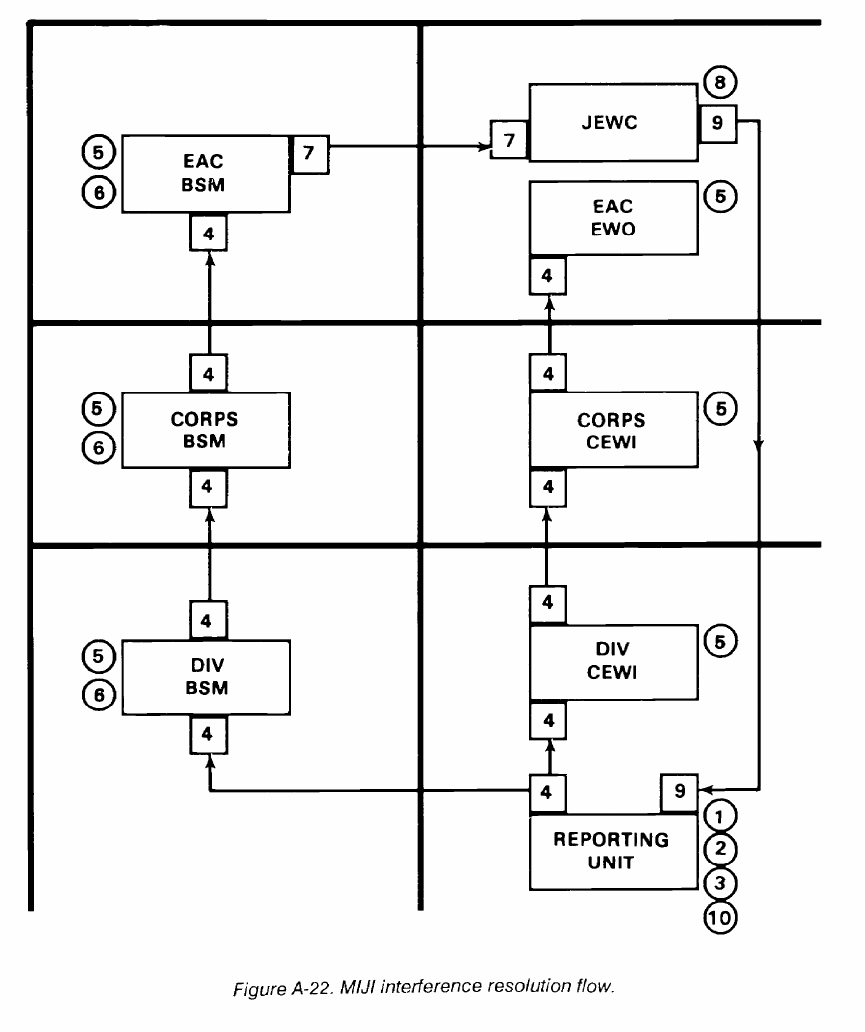
FM 24-2
A-37
FM 24-2
Appendix B
Interference Charts
B-1. Description and Use
The interference charts in this appendix can be used in
determining the distance separation required for
cochannel and adjacent channel operation. Distance
separation charts indicate the spacing needed between
stations under different conditions of transmitter power
output and types of emission. Interfering equipment is
referred to as the undesired transmitter. Equipment
interfered with is called the receiver and desired
transmitter.
The following services are covered by the charts: AM
SSB voice, teletype, and FM voice/data. Two charts are
shown for each type of service. One chart is for use when
the desired and undesired transmitters are on the same
frequency; the other chart is used when the undesired
transmitter is on an adjacent channel separated by the
frequency indicated.
B-2. Sample Problem
Problem.
A desired transmitter and the desired receiver are
operating an FM voice net on low power (8 watts) located
3 miles apart. What is the minimum distance a high power
(35 watts) FM transmitter operating on the same frequency
can be placed from the desired receiver without causing
interference?
Solution.
Since the desired signal is FM voice, the desired
transmitter and receiver are operating on low power. The
undesired transmitter is operating on high power and all
are on the same frequency (Figure B-1).
The ratio of the undesired transmitter power to the
desired transmitter power is 35 to 8 (about 4 to 1).
Enter the chart on the horizontal scale at the 3-mile
point and extend a vertical line from this point until it meets
the curve corresponding to a ratio of 4 to 1.
The curve corresponding to a ratio of 4 to 1 is not shown
on the chart, but its position is found by interpolating
between the 1 to 1 and 10 to 1 curves.
From this point, a horizontal line is drawn to the left until
it intersects the vertical scale which indicates a distance of
6 miles.
Therefore, the minimum distance that the 35-watt
undesired transmitter must be separated from the receiver
is 6 miles.
NOTE: Interpolation is logarithmic between curves
and gridlines.
B-3. Special Considerations
The adjacent channel charts are for 5-kHz separation
(using 11 MHz frequency for SSB-voice AM equipment)
and 50-kHz separation (using 53 MHz frequency for FM
equipment). Any interfering equipment with less channel
separation from the receiver than indicated in these charts
results in a greater required distance separation from the
desired receiver, and should be sited using the
same-channel charts.
Figures B-1 and B-2 are charts for FM equipment based
on the characteristics of the AN/VRC-12 series radio.
These charts apply to equipment having similar
characteristics as to maximum frequency deviation,
selectivity, and frequency stability. Figures B-3 and B-4 are
interference charts for SINCGARS versus SINCGARS.
Figures B-5 through B-12 are interference charts for
SINCGARS versus AN/VRC-12 series radio. Figure B-13
is an interference chart for AN/PRC-77 versus
SINCGARS. Figures B-14 through B-17 are charts for SSB
equipment based on the characteristics of the
AN/GRC-106 radio set. These charts apply to equipment
having similar characteristics as to modulation, selectivity,
and frequency stability.
Only ground wave and direct wave transmissions were
considered in preparing these charts. Propagation over a
smooth spherical earth and using 15-foot vertical whip
antennas were considered, based on cochannel
signal-to-interference thresholds of AN/VRC-12, 6 dB;
AN/GRC-106, SSB, 4 dB; and AN/GRC-106, teletype, 9
dB.
B-1
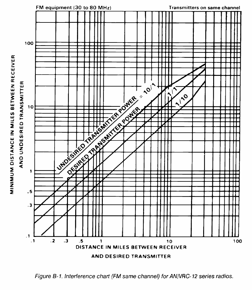
FM 24-2
Mutual interference problems often result when FM
the AN/PRC-25, AN/PRC-77, and the vehicular versions
transmitters operating on different frequencies are
of these radios. These interference problems can be
situated in the same locale. The problem can occur
effectively reduced when the following basic assignment
between AN/VRC-12 series radios and also between these
standards are followed.
radios and low power FM radios. These radio sets include
B-2
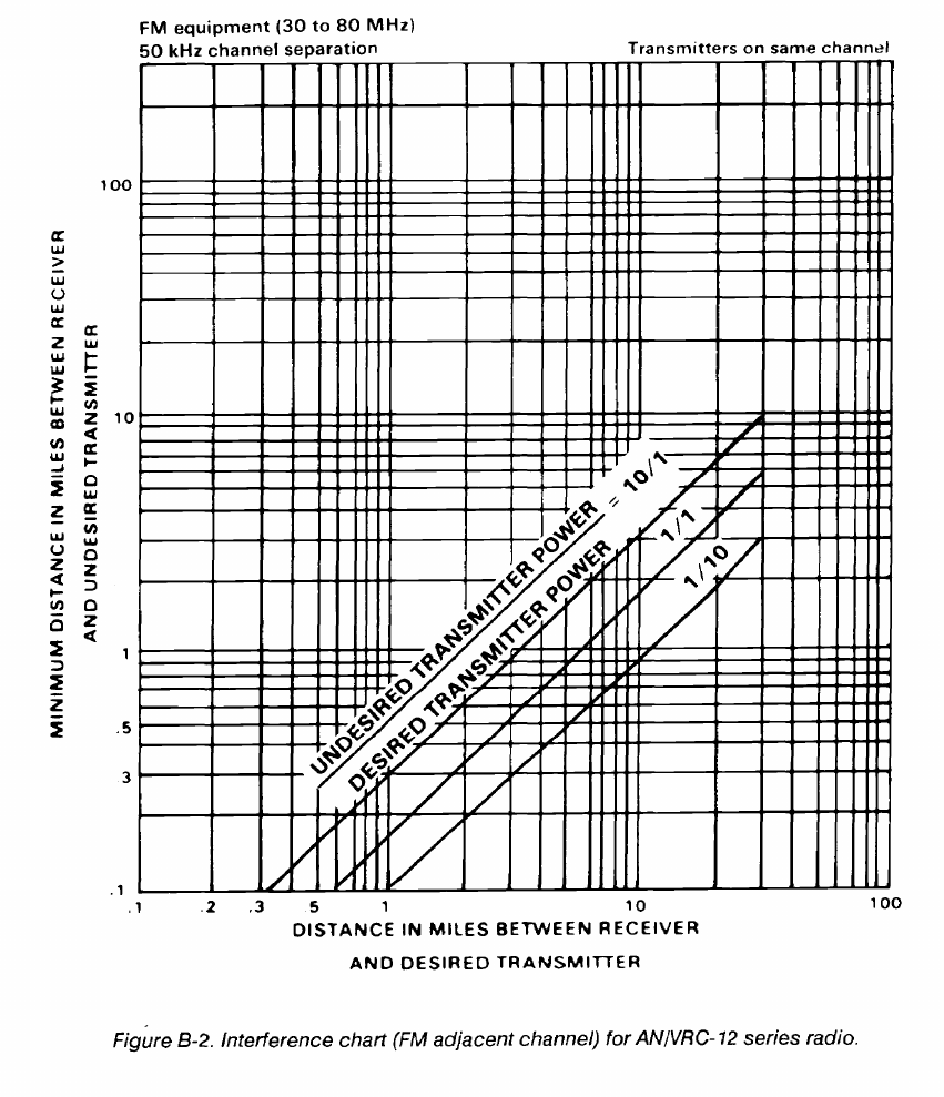
FM 24-2
B-3
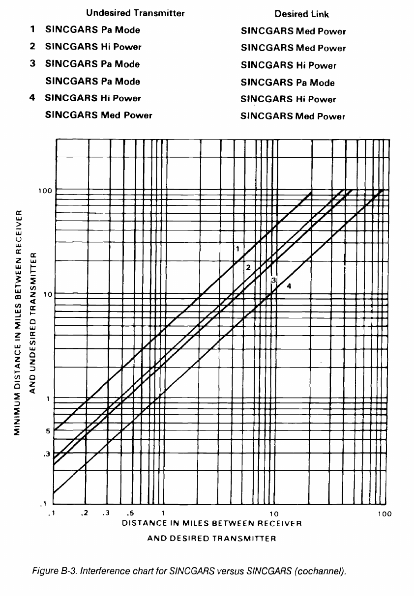
FM 24-2
B-4
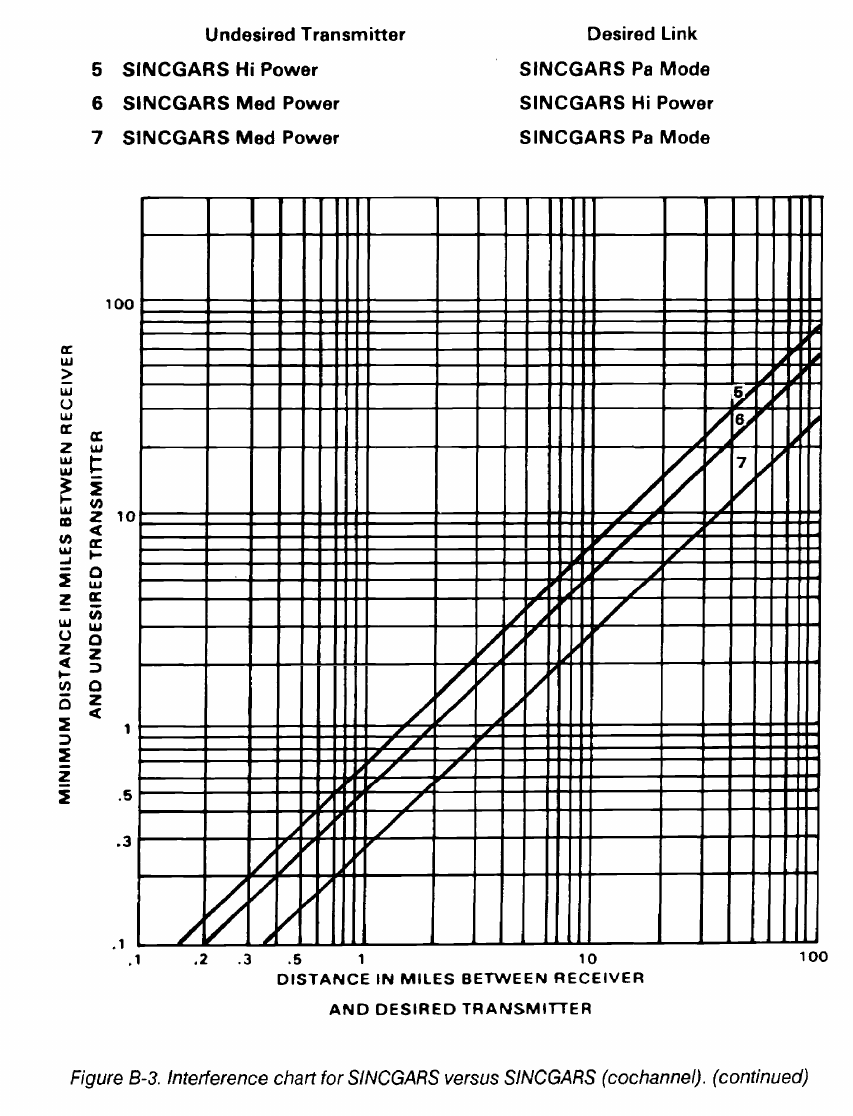
FM 24-2
B-5
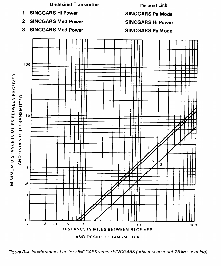
FM 24-2
B-6
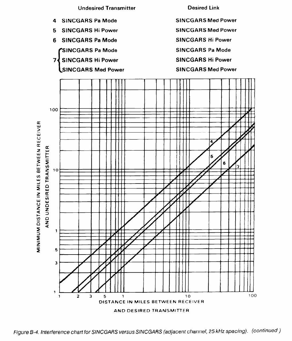
FM 24-2
B-7
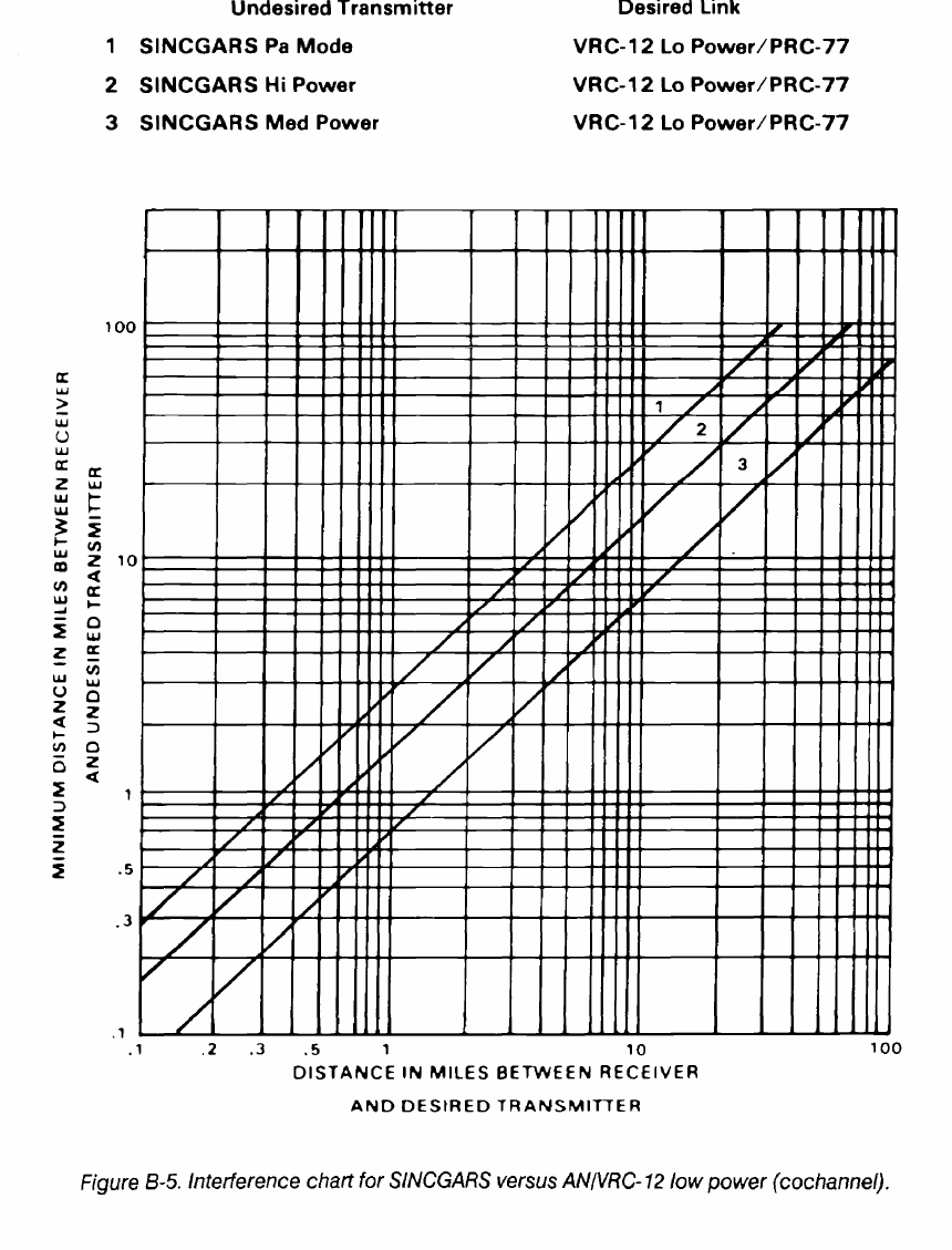
FM 24-2
B-8
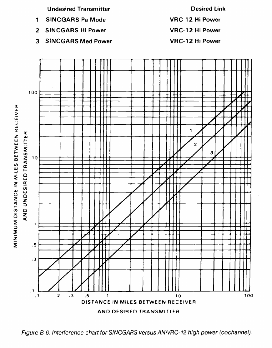
FM 24-2
B-9
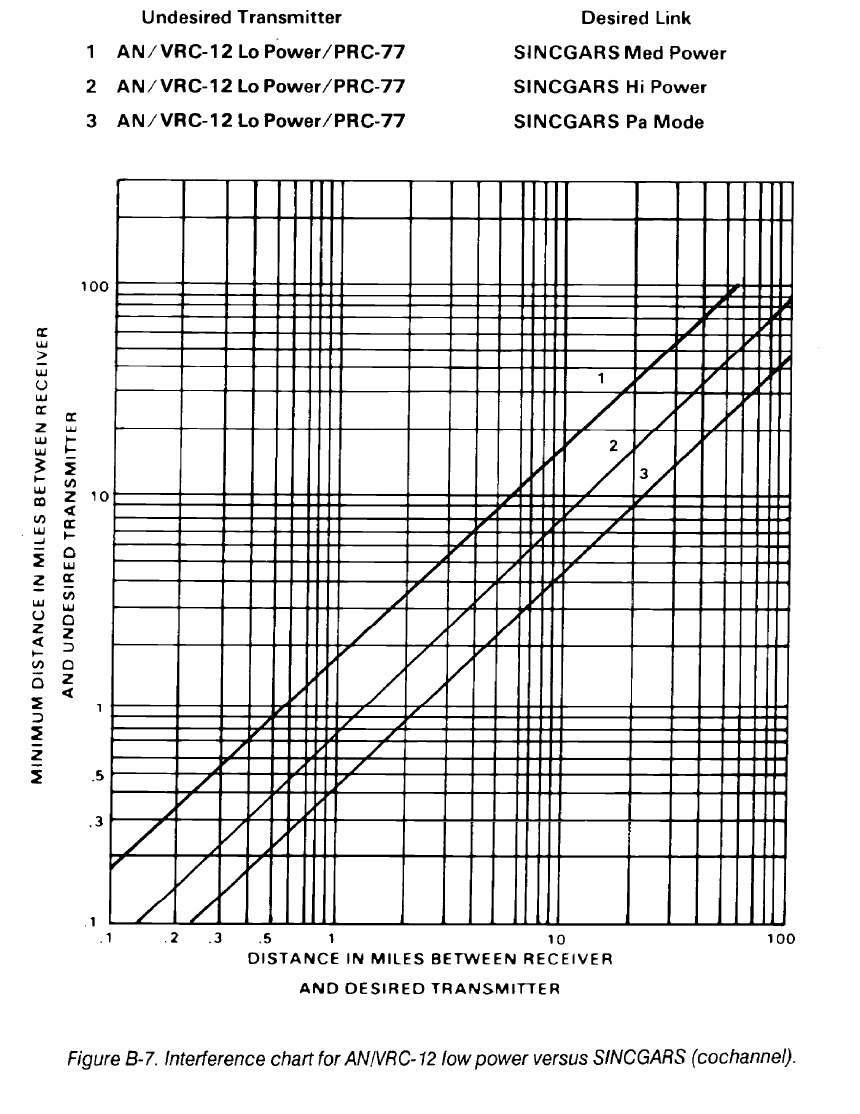
FM 24-2
B-10

FM 24-2
B-11
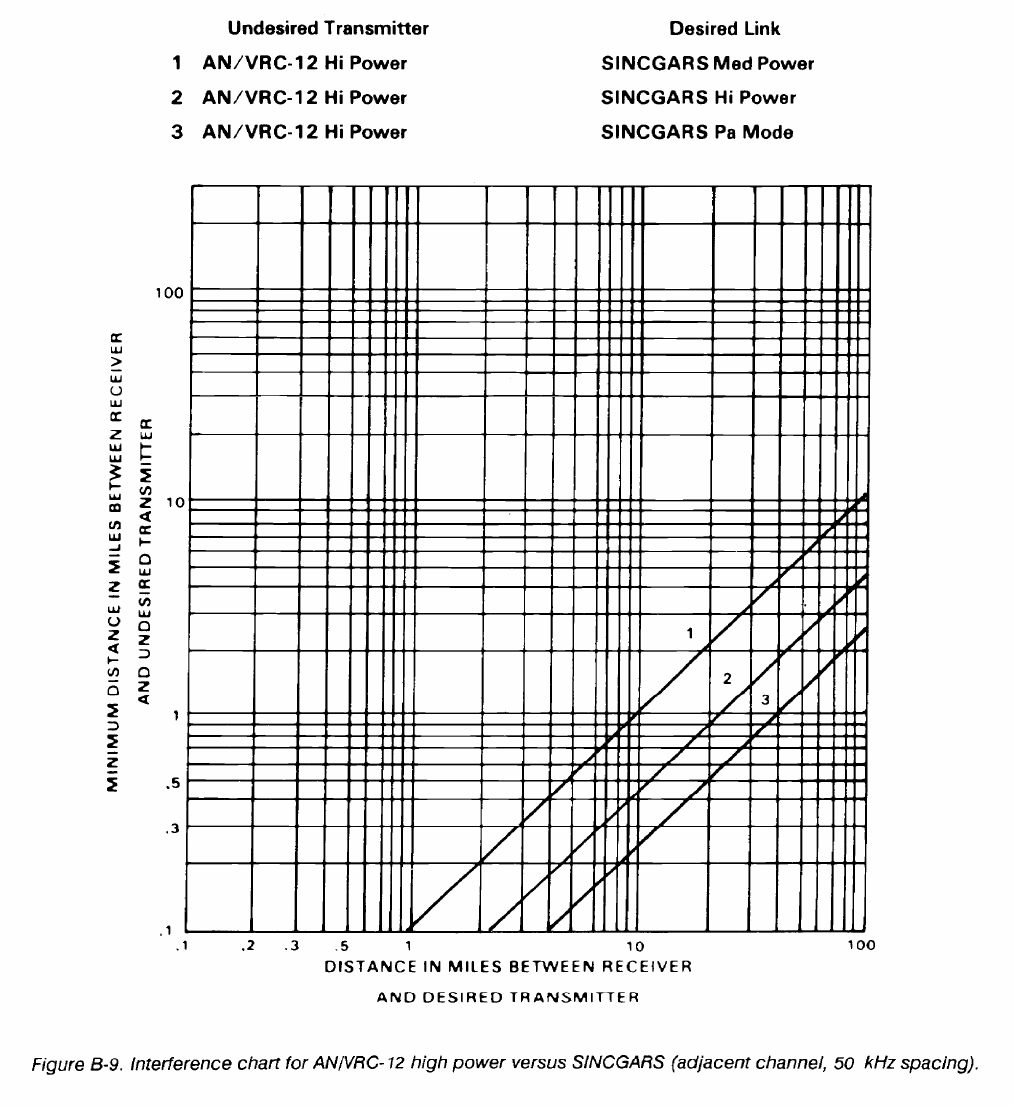
FM 24-2
B-12
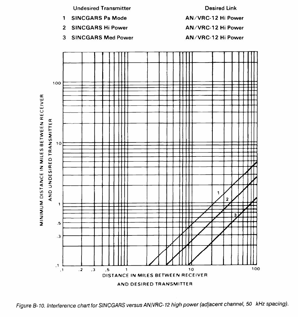
FM 24-2
B-13
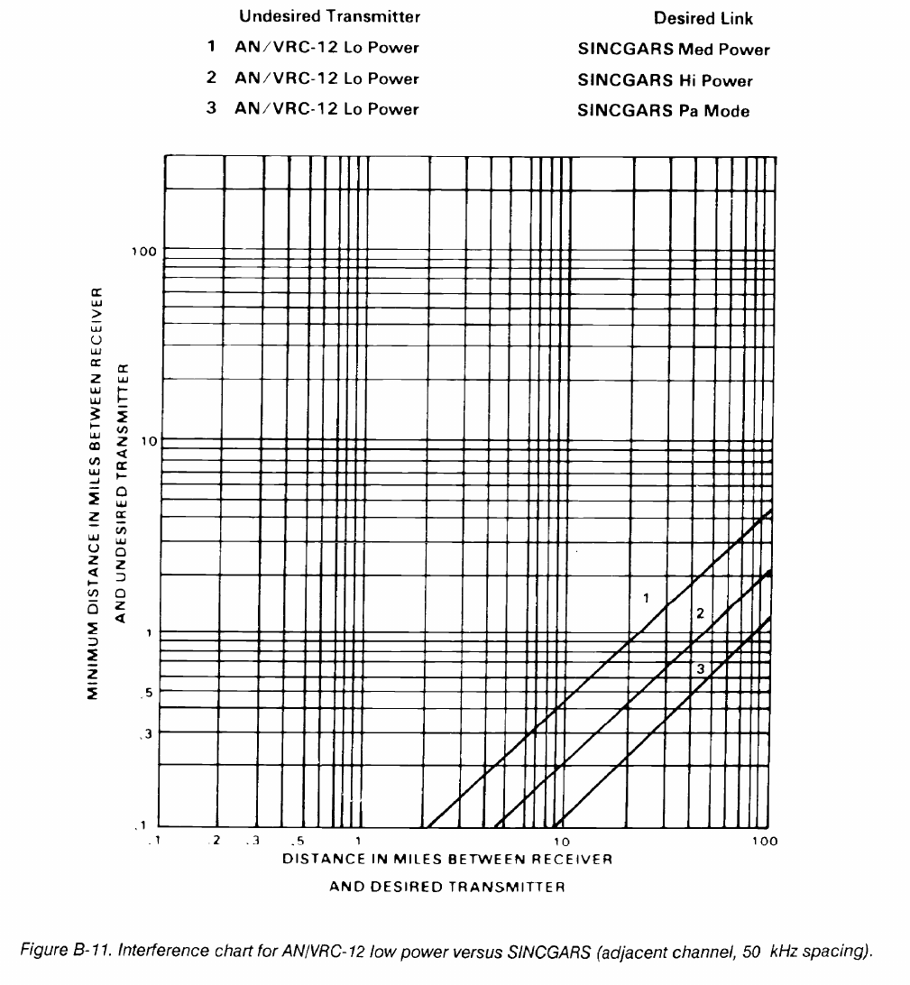
FM 24-2
B-14
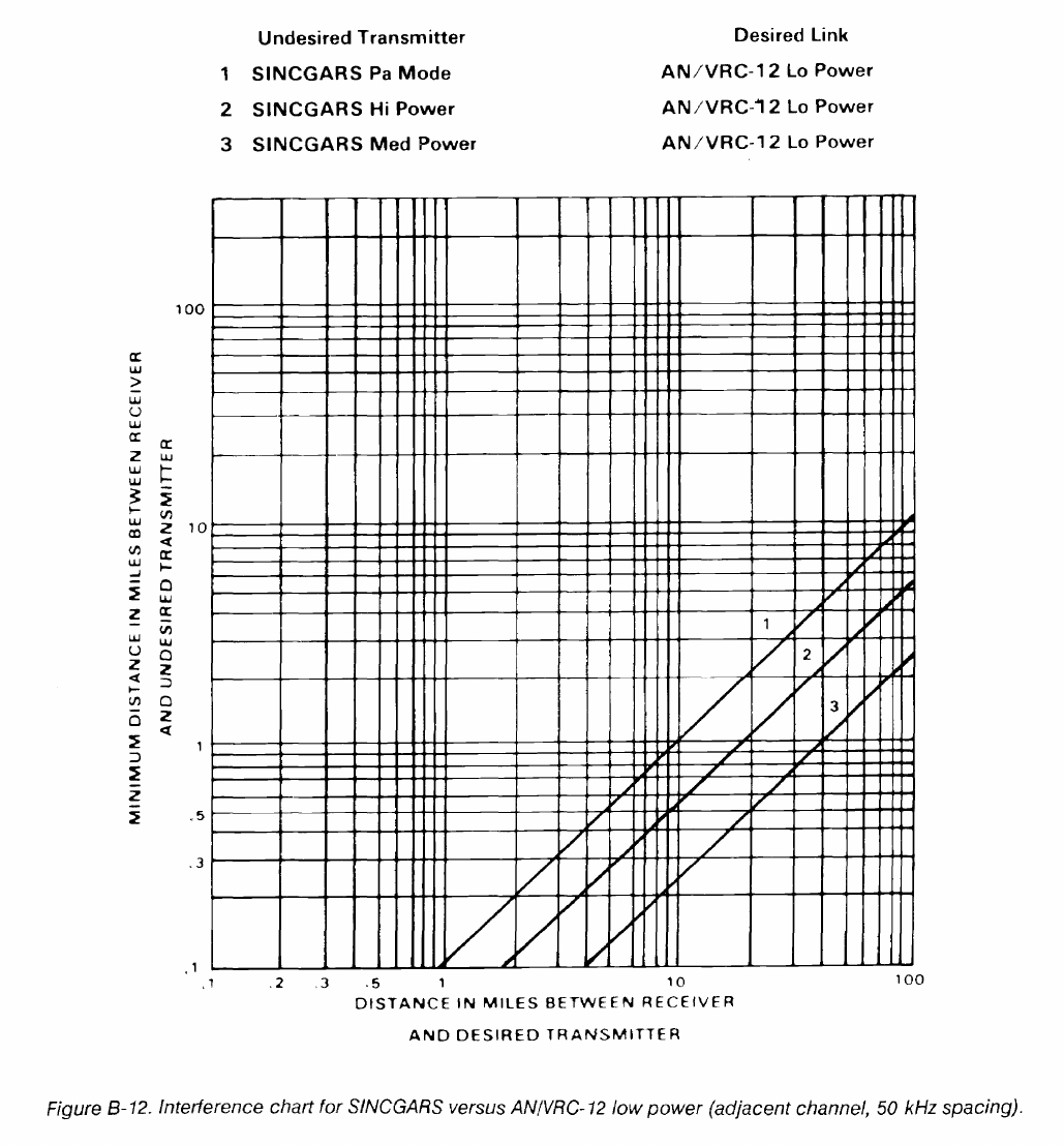
FM 24-2
B-15
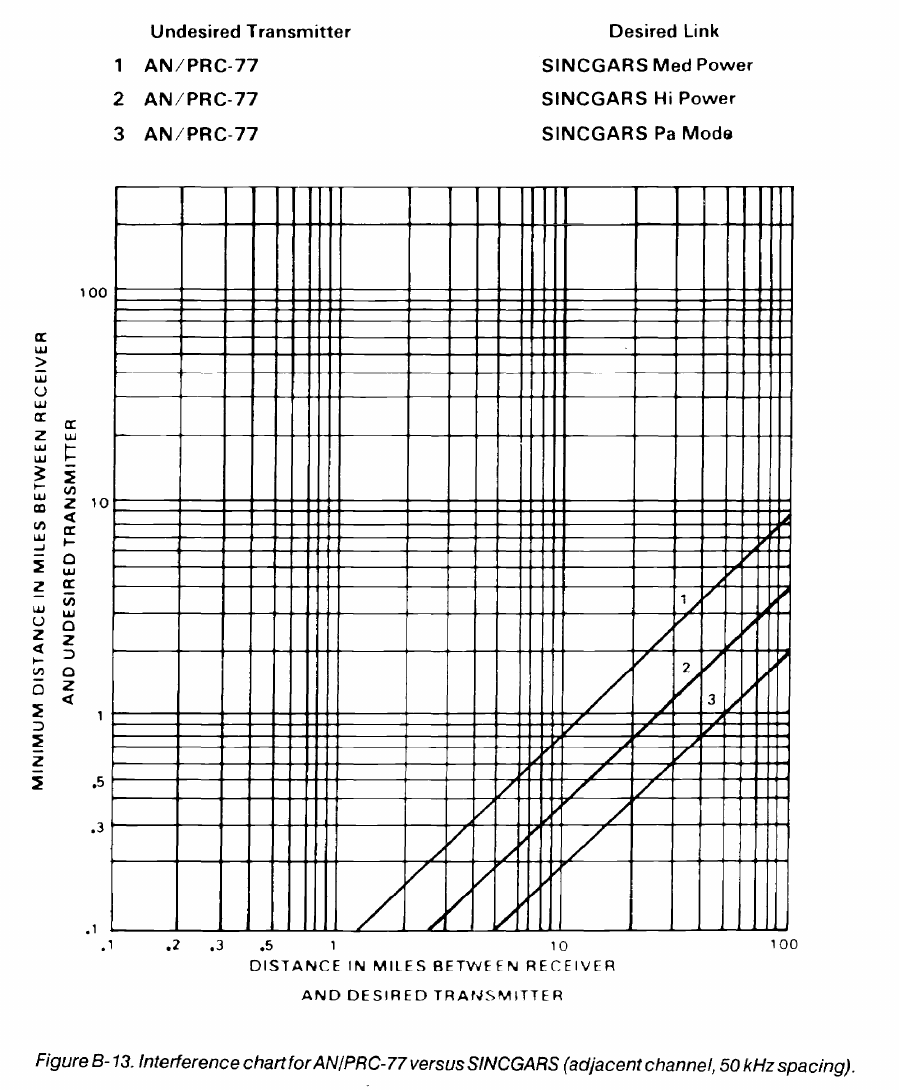
FM 24-2
B-16
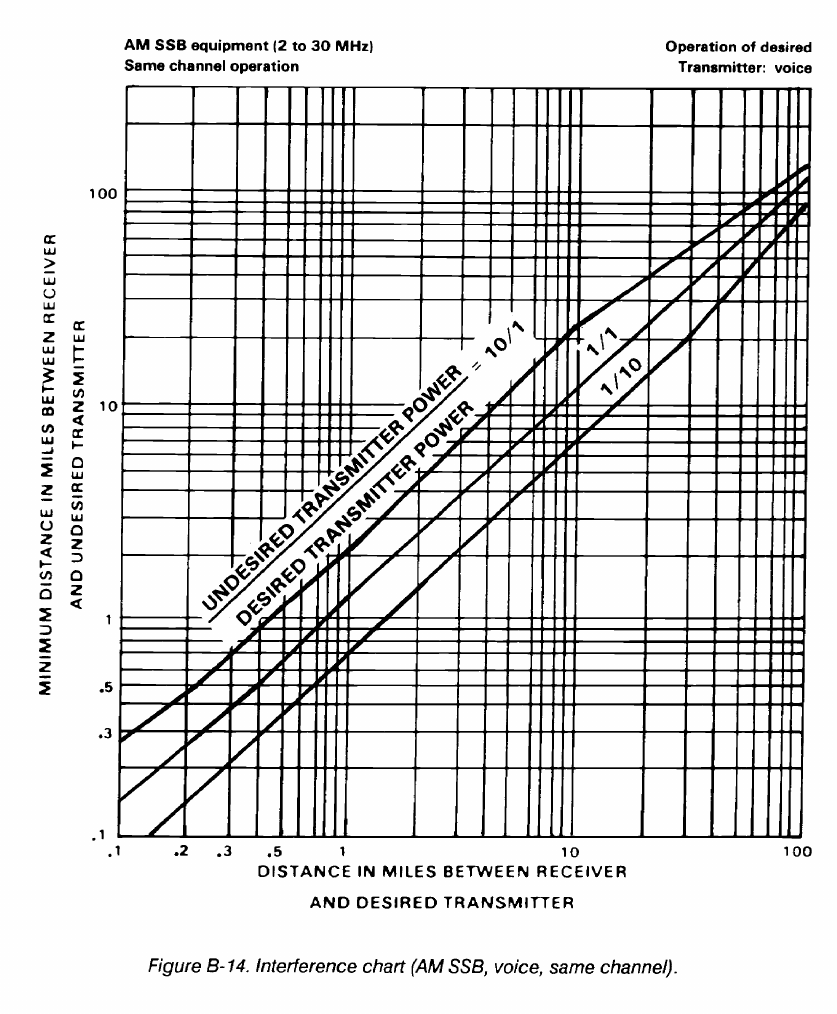
FM 24-2
B-17
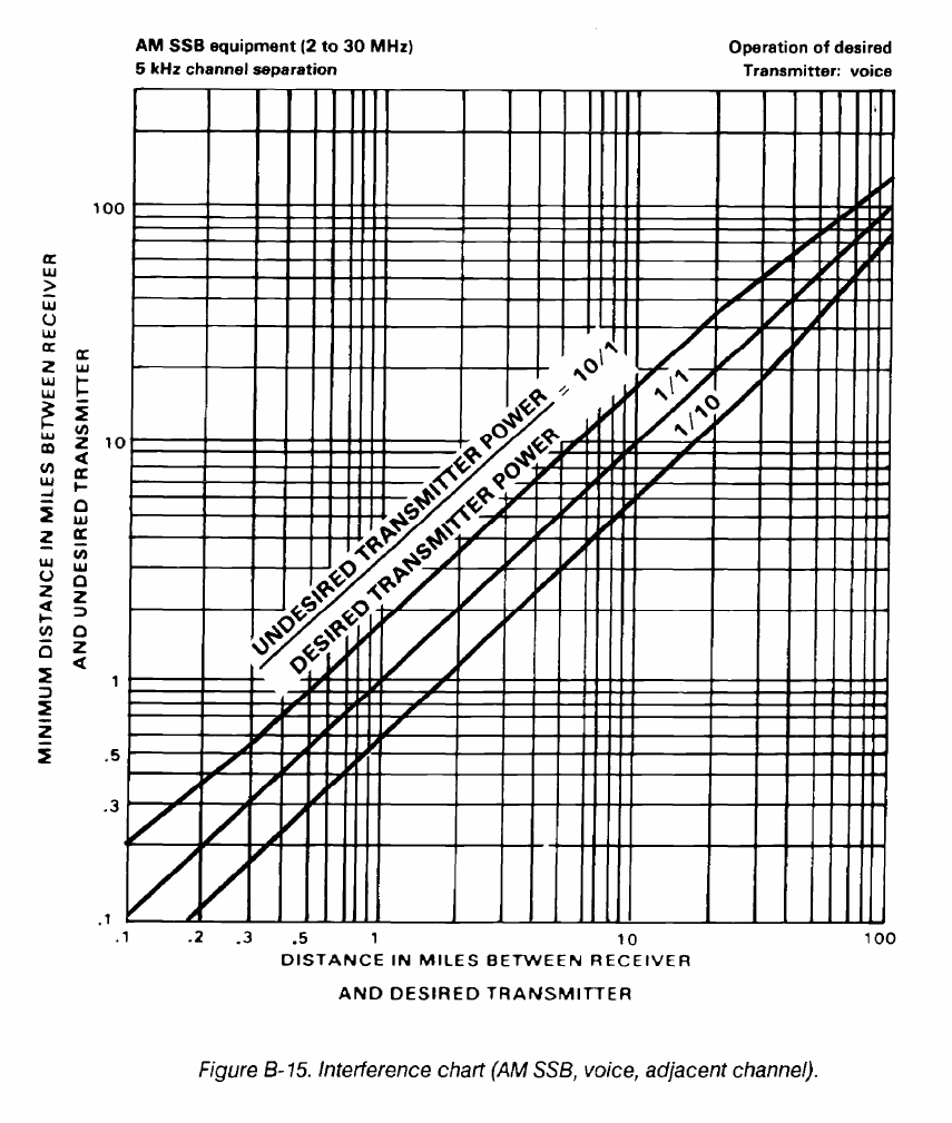
FM 24-2
B-18
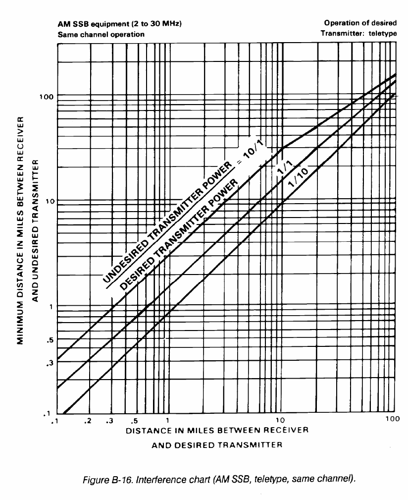
FM 24-2
B-19
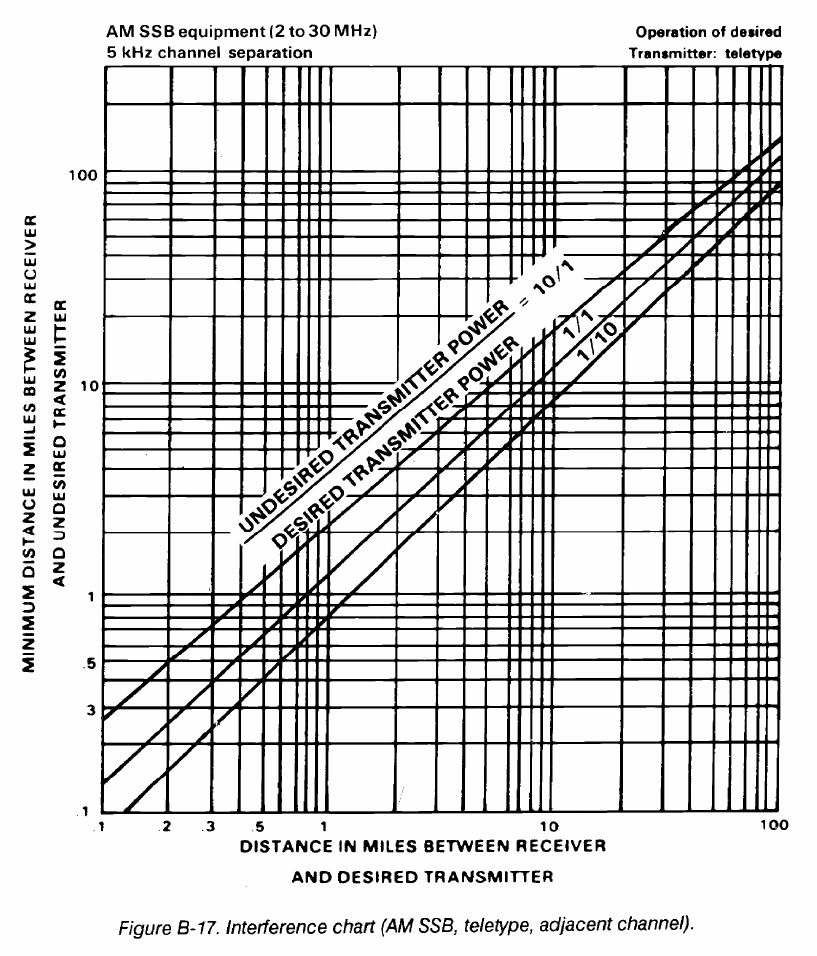
FM 24-2
When using the AN/VRC-12 series radio, avoid using
frequencies that are harmonically related. For example,
frequencies that are separated by exactly 5.75 or 23.00
MHz.
Do not assign frequencies to collocated nets that are on
the order of the second harmonic. For example, the
frequency setting of 30.00, 32.65, and 35.00 MHz will
possibly interfere with a radio using 60.00,65.30, and 70.00
MHz, respectively.
Observe the recommended minimum frequency versus
distance restrictions given in Table B-1.
B-20
High frequency AM nets experience fewer interference
problems than VHF, FM nets; however, some interference
may result when these radios are operated in the same
vicinity. Therefore, collocated HF nets should be assigned
frequencies at least 100 kHz apart. RATT nets operating
in the FULL-DUPLEX mode, with the transmitter and
receiver on different frequencies, require a frequency
separation of at least 400 kHz.
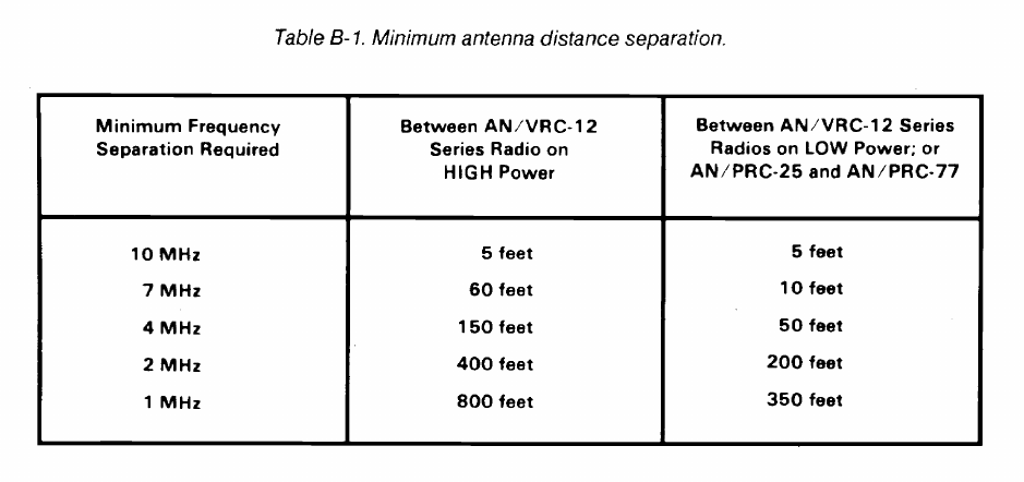
FM 24-2
8-21
FM 24-2
Appendix C
Procedure for Field Level Selection and
Coordination of RF Use
C-1. FAA Coordinators
FAA coordinators and geographical areas of
responsibility for the frequency 1030 MHz and the bands
1215 to 1400 MHz, 2700 to 2900 MHz, and 9000 to 9200
MHz are shown below. (See Figure C-l).
Northwest Mountain Region
Spectrum Management Officer, ANM-464
Federal Aviation Administration
17900 Pacific Highway South C-68966
Seattle, Washington 98168
Telephone: 206-431 -2407/2473/2503/2464
Colorado; Idaho; Montana; Oregon; Utah;
Washington; Wyoming.
Western Pacific Region
Spectrum Management Officer, AWP-406
Federal Aviation Administration
P.0. B
OX
92007
Los Angeles, California 90009
Telephone: 213-297- 1165/1685/1342/1164/
1872/0214/0510/0276
Arizona; California
j
including all offshore islands;
Nevada.
Central Region
Spectrum Management Officer, ACE-433
Federal Aviation Administration
601 12th Street
Kansas City, Missouri 64106
Telephone: 816-426-5036/5647
Iowa; Kansas; Missouri; Nebraska.
Southwest Region
Spectrum Management Officer, ASW-465
Federal Aviation Administration
Fort Worth, Texas 76193-0465
Telephone: 817-624-5466/5465/5458/5467/5469
Arkansas; Louisiana; New Mexico; Oklahoma; Texas.
Great Lakes Region
Spectrum Management Officer, AGL-423
Federal Aviation Administration
2300 East Devon Avenue
Des Plaines, Illinois 60018
Telephone: 312-694-7332/7363/7616/7842/7071
Illinois; Indiana; Michigan; Minnesota; North Dakota;
South Dakota; Ohio; Wisconsin.
Southern Region
Spectrum Management Officer, ASO-465
Federal Aviation Administration
P.O. B
OX
20636
Atlanta, Georgia 30320
Telephone: 404-763-7385/7386
Alabama; Florida; Georgia; Kentucky; Mississippi;
North Carolina; Puerto Rico; South Carolina;
Tennessee; US Possessions in the Caribbean; Virgin
Islands.
Eastern Region
Spectrum Management Officer, AEA-435
Federal Aviation Administration
Fitzgerald Federal Building
JFK International Airport
Jamaica, New York 11430
Telephone: 718-917-1191
Delaware; District of’ Columbia; Maryland; New Jersey;
New York; Pennsylvania; Virginia; West Virginia.
New England Region
Spectrum Management Officer, ANE-461
Federal Aviation Administration
12 New England Executive Park
Burlington, Massachusetts 01803
Telephone: 617-273-7160/2408/7197
Connecticut; Maine; Massachusetts; New Hampshire;
Rhode Island; Vermont.
C-1
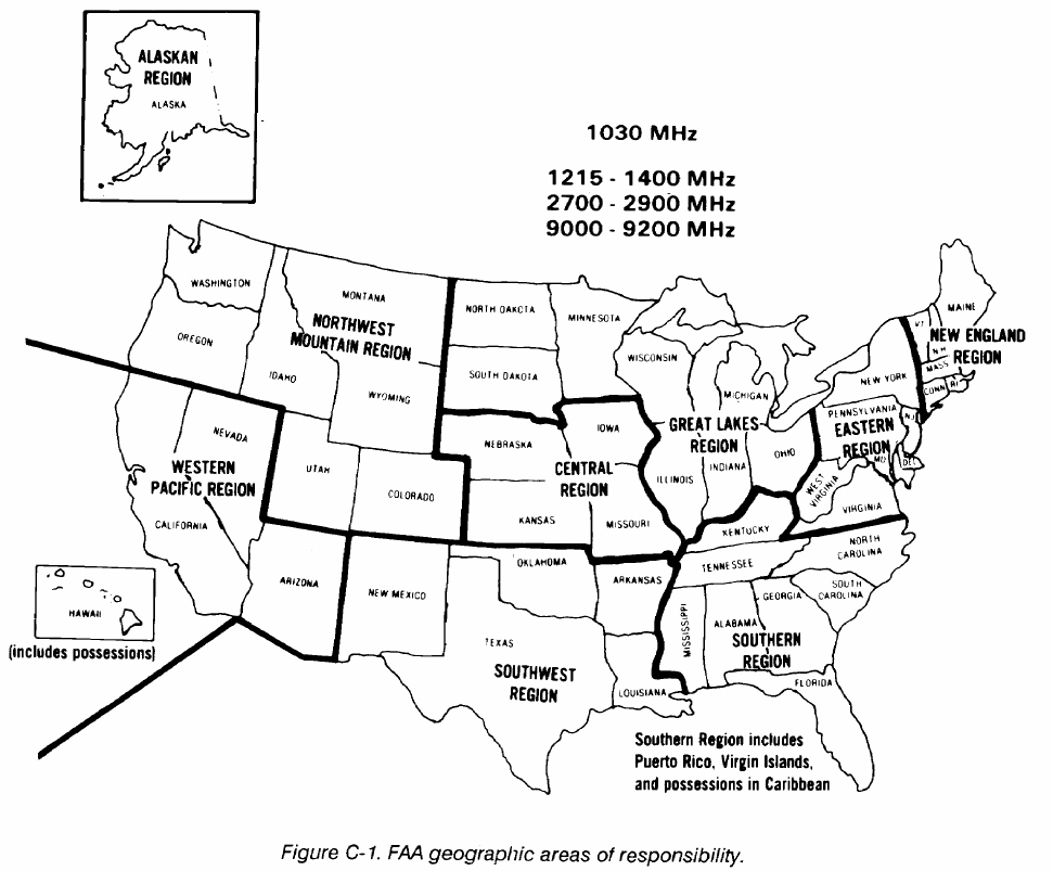
FM 24-2
Alaskan Region
Western Pacific Hawaii Region
Spectrum Management Officer, AAL-464B
Federal Aviation Administration
701 C Street, P.O. B
OX
14
Anchorage, Alaska 99513-0087
Telephone: 907-271-5343
Alaska.
Spectrum Management Officer, AWP-406H
Federal Aviation Administration
Diamond Head SFO
4204 Diamond Head Road
Honolulu, Hawaii 96816-4420
Telephone: 808-734-6627
Hawaii; US Possessions in the Pacific Ocean.
C-2
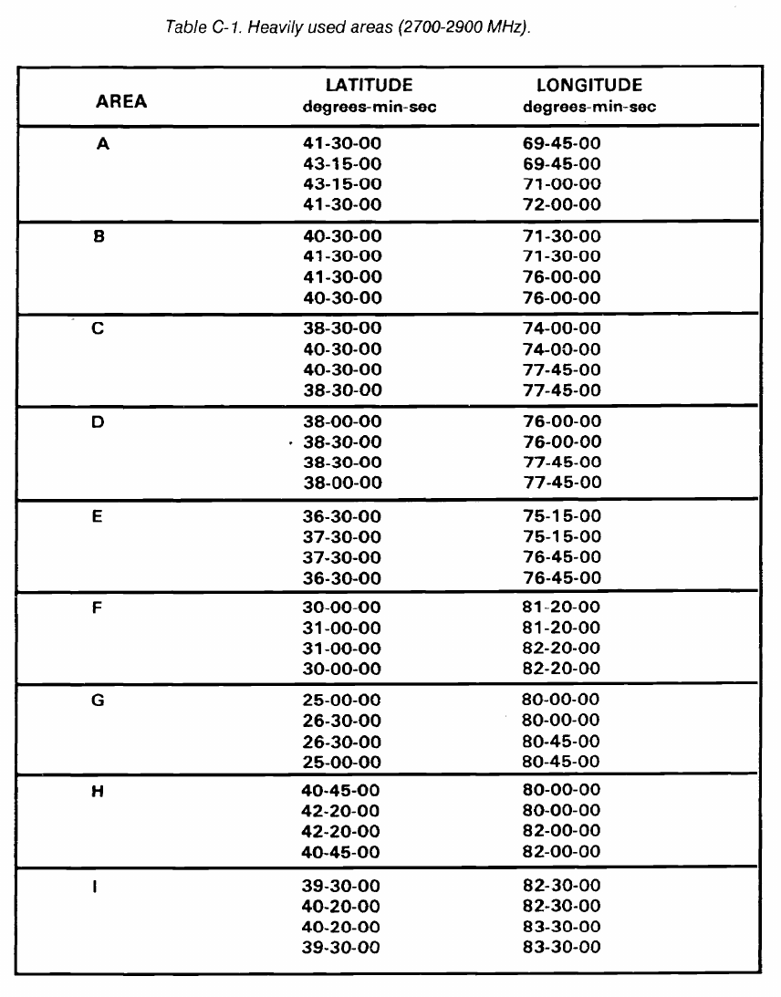
FM 24-2
Table C-1 shows the designated heavily used areas in
the 2700 to 2900 MHz band. Figure C-2 is a geographic
presentation of these areas.
C-3
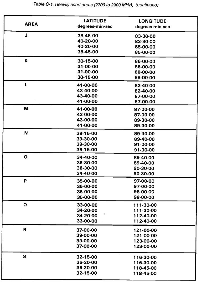
FM 24-2
C-4
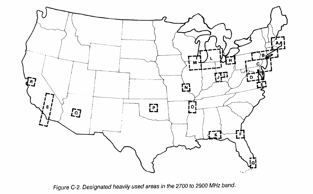
FM 24-2
C-2. Field Level Coordinators
Government area frequency coordinators and
geographical areas of responsibility for bands
1435 to 1535 MHz and 2310 to 2390 MHz are shown
below. (See Figures C-3 and C-4.)
Area Frequency Coordinator
Nellis AFB, Nevada 89191
Telephone: 702-643-3608
DSN: 682-3608
Nevada; Utah west of 1ll
O
W; Idaho south of
44
O
N.
Area Frequency Coordinator
State of Arizona
Fort Huachuca, Arizona 85613-5000
Telephone: 602-538-6423
DSN: 879-6423
Arizona.
Area Frequency Coordinator
White Sands Missile Range,
New Mexico 88002-5526
Telephone: 1505-678-5417
DSN: 258-3702
Colorado west of 108°W; New Mexico; Texas
west of 104°W; Utah east of lll°W.
Gulf Area Frequency Coordinator
Elgin AFB, Florida 32542
Telephone: 904-882-4416
DSN: 872-4416
Alabama south of 33°30’N; Florida west of 83°W,
Georgia west of 83°W, south of 33°30’N;
Louisiana east of 90°W; Mississippi east of
90°W, south of 33°30’N.
Eastern Area Frequency Coordinator
Patrick AFB, Florida 32925
Telephone: 305-494-5366
DSN: 854-5366
Florida east of 83°W; Georgia east of 83°W, south
of 31°30’N.
Mid-Atlantic Area Frequency Coordinator
Department of the Navy
Naval Air Test Center
Patuxent River, Maryland 20670
Telephone: 301-863-1188
DSN: 356-1188
That area of the eastern US and the Atlantic
Ocean south of 41°N; east of a line starting at
the intersection of 41°N and 75°30’W running
southwest to the intersection of 33°30’N and
83°W, then south to the intersection of 31°30’N
and 83°W; north of 31°30’N; west of 68°40’W.
C-5
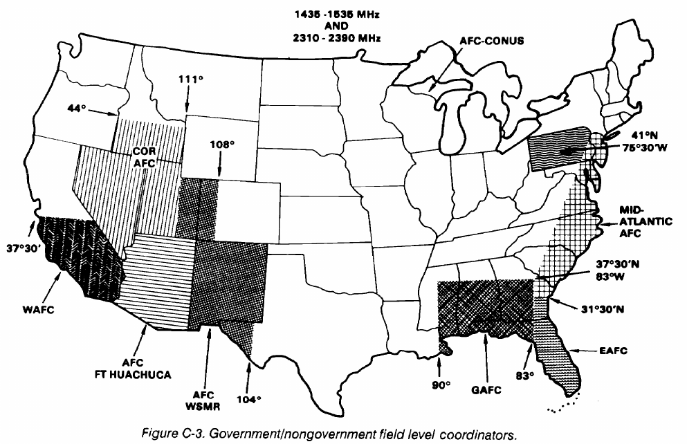
FM 24-2
Army Frequency Coordinator
Military District of Washington
Military District of Washington, DC 20319-5050
Telephone: 202-693-5154
DSN: 223-5154
District of Columbia; county of Arlington (less
Fort Belvoir but including Davison AAF) and
the city of Alexandria in the state of Virginia;
counties of Montgomery and Prince Georges
in the state of Maryland.
Commander
USAISC - Alaska
ATTN: CCNA-AK-CE
Fort Richardson, Alaska 99505
Telephone: 317-862-6294
DSN: 863-6294
Alaska.
Commander
US Army Pacific
ATTN: APCE
Fort Shafter, Hawaii 96858
Telephone: 808-438-2261
Hawaii.
Area Frequency Coordinator (Air Force)
Headquarters Alaskan Air Command/DCT
Elmendorf AFB, Alaska 99506
Telephone: 907-752-2283
DSN: 317-752-2283
Alaska; established DOD area frequency
coordinator for all frequency use within the
state of Alaska.
Area Frequency Coordinator
Department of the Air Force
USAF Frequency Management Center
Washington, DC 20330-6431
Telephone: 202-475-1825
DSN: 335-1825
Alabama north of 33°30’N: Connecticut:
Kentucky; Maine; Massachusetts; Mississippi
less east of 90°W, south of 33°30’N; New
Hampshire; New Jersey north of 41°N; New
York north of 41°N; Ohio; Rhode Island;
Tennessee; Vermont; West Virginia; and those
areas of the following states west of the
Mid-Atlantic AFC area: Georgia north of
33°30’N; Maryland; North Carolina;
Pennsylvania including that north of 41°N;
South Carolina; Virginia.
C-6
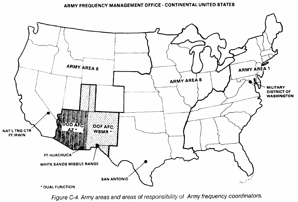
FM 24-2
Army Frequency Management Office
Continental United States
ATTN: SFIS-FAC-SC
Fort Sam Houston, Texas 78234-5000
Telephone: 512-221-7050/2820
DSN: 471-7050/2820
Alabama, Arkansas, California (less units
located on or conducting training of the Army
National Training Center, Fort Irwin, CA),
Colorado, (less the area west of 108°W),
Connecticut, Delaware, Florida, Georgia,
Idaho, Illinois, Indiana, Iowa, Kansas,
Kentucky, Louisiana, Maine, Maryland (less
certain areas which are included in the
Military District of Washington),
Massachusetts, Michigan, Minnesota,
Mississippi, Missouri, Montana, Nebraska,
Nevada, New Hampshire, New Jersey, New
York, North Carolina, North Dakota, Ohio,
Oklahoma, Oregon, Pennsylvania, Rhode Island,
South Carolina, South Dakota, Tennessee,
Texas (less Fort Bliss and US Territory within
150-mile radius of White Sands Missile Range),
Utah (less the area east of 111 ‘W), Vermont,
Virginia (less certain areas which are included
in the Military District of Washington),
Washington, West Virginia, Wisconsin and
Wyoming.
Commander, USAISC
AT TN: ASQNA-IRW-CO
Fort Irwin, CA 92310-5000
Telephone: 619-386-3280
DSN: 470-3280
Coordinates directly with units scheduled for
rotation training at the Army National
Training Center to define frequency
requirements and to coordinate closely with
the western area frequency coordinator, Point
MUGU and AFMO-CONUS in the final
coordination process.
C-7
FM 24-2
Commander, USA Kwajalein Atoll (USAKA)
The nongovernment Aerospace and Flight Test
P.O. Box 26
Radio Coordinating Council (AFTRCC) coordi-
APO San Francisco, 96555-008
nator is shown below.
DSN: 254-2111
Aerospace and Flight Test Radio Coordinating
Coordinates frequencies enclosed within a
Council
200-mile radius of the Headquarters Building,
P.0. BOX 718
USAKA.
Hawthorne, California 90251
Telephone: 213-970-6563
C-8
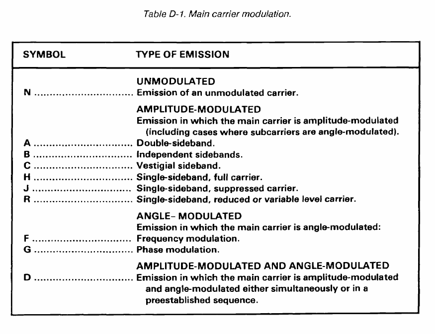
FM 24-2
Appendix D
Radio Emission Designator
•
•
•
•
•
The emission designator consists of the necessary
bandwidth and emission classification symbols. The
symbols are shown below.
First symbol - Indicates the type of modulation of
the main carrier. (See Table D-1.)
Second symbol - Indicates the nature of signal(s)
modulating the main carrier. (See Table D-2.)
Third symbol - Indicates the type of information
transmitted. (See Table D-3.)
Fourth symbol - Indicates the details of the signal
(Optional - recommend use when applicable).
(See Table D-4.)
Fifth symbol - Indicates the nature of multiplex-
ing (Optional - recommend use when applicable).
(See Table D-5.)
D-1
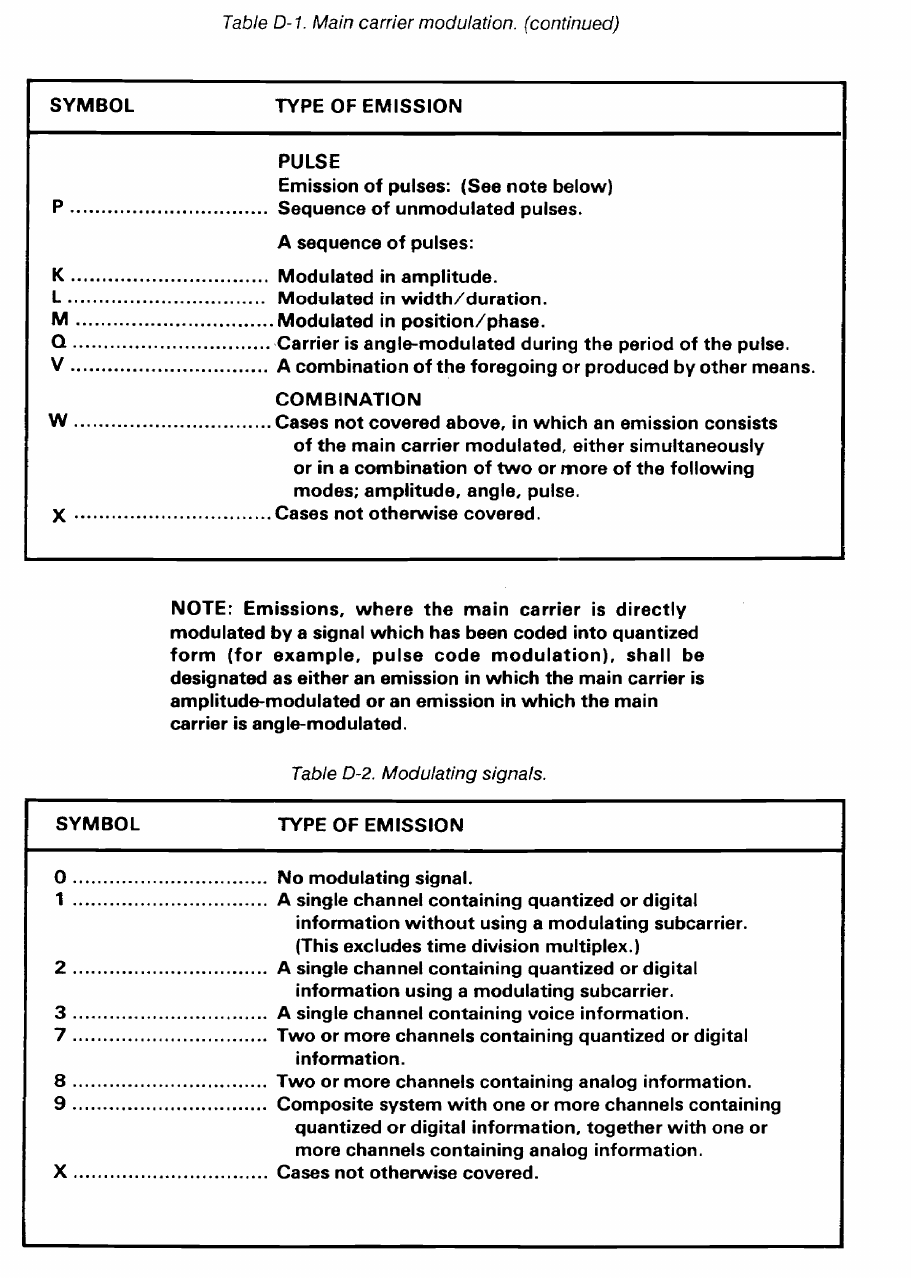
FM 24-2
D-2
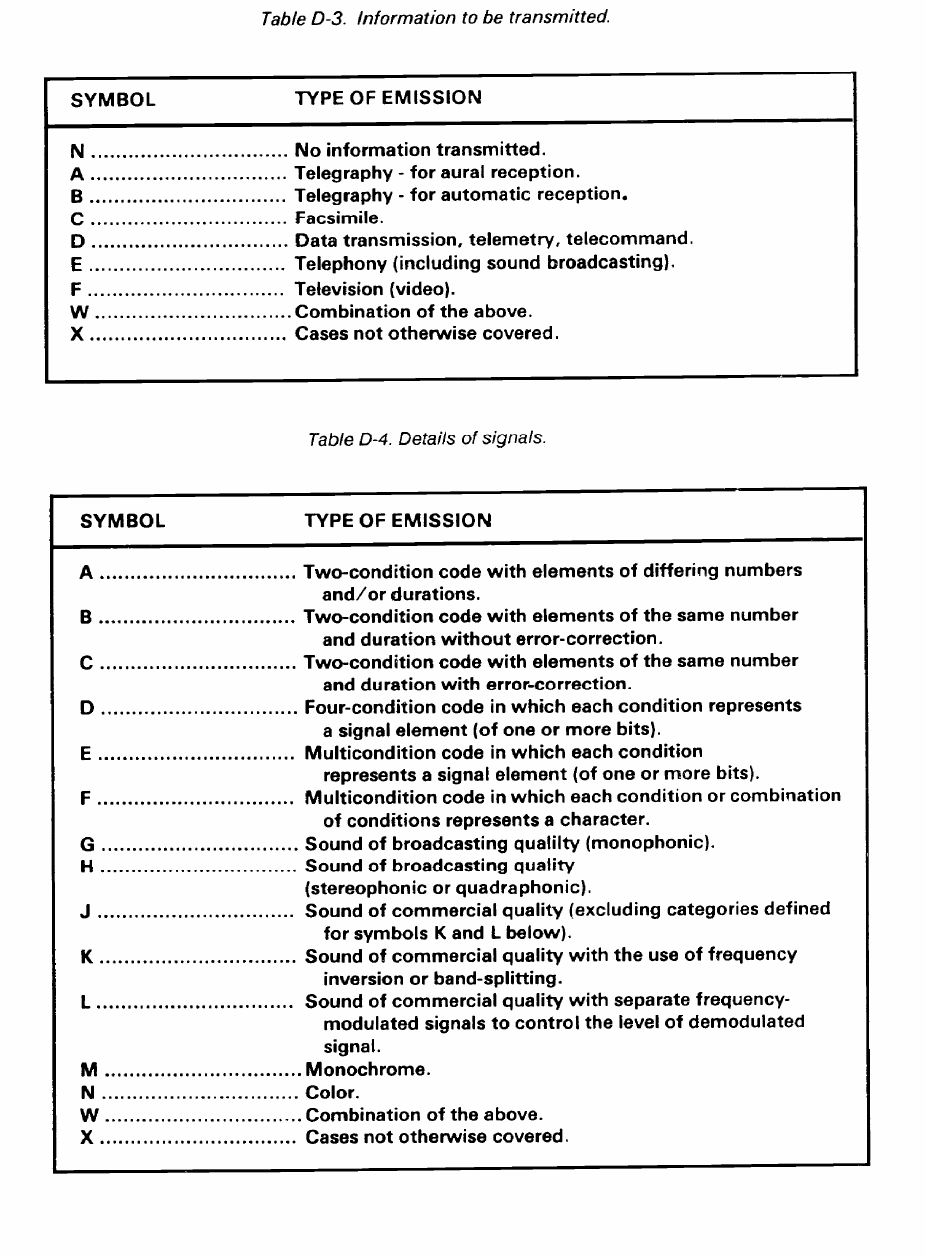
FM 24-2
D-3

FM 24-2
•
•
The emission designator shall be entered according to
the rules shown below.
To express the necessary bandwidth portion of
the emission designator, enter a maximum of five
numerals and one letter. The letter occupies the
position of the decimal point and represents the
unit of bandwidth as follows: H for hertz, K for
kilohertz, M for megahertz, and G for gigahertz.
Fractional bandwidths may be expressed to a max-
imum of two decimal places following the letter.
The first character of the necessary bandwidth
shall always be greater than zero unless the neces-
sary bandwidth is less than 1 hertz. In such a case,
the first character shall be the letter H. Express
the necessary bandwidths according to the discus-
sion below.
Necessary bandwidths between .01 and 999.99 Hz
shall be expressed in hertz using the letter H in-
stead of the decimal. (For example, 15H is 15 Hz
of bandwidth; 15H01 is 15.01 Hz of bandwidth.)
Necessary bandwidths between 1.00 and 999.99
kHz shall be expressed in kilohertz using the let-
ter K instead of the decimal. (For example, 2K is
2 kHz of bandwidth; 2K85 is 2.85 kHz of
bandwidth.)
Necessary bandwidths between 1.00 and 999.99
MHz shall be expressed in megahertz using the
letter M instead of the decimal. (For example,
6M is 6 MHz of bandwidth; 6M25 is 6.25 MHz of
bandwidth.)
•
D-4
Necessary bandwidths between 1.00 and 999.99
GHz shall be expressed in gigahertz using the let-
ter G instead of the decimal, (For example, 10G
is 10 GHz of bandwidth; 10G05 is 10.05 GHz of
bandwidth.)
Enter the basic emission designator of three sym-
bols, and if desired, two optional, additional sym-
bols, derived from the following:
The first symbol designates the main carrier’s
type of modulation. (See Table D-l.)
The second symbol designates the nature of sig-
nal(s) modulating the main carrier. (See Table D-
2.)
The third symbol designates the type of infor-
mation transmitted. In this context the word infor-
mation does not include information of a
constant, unvarying nature such as provided by
standard frequency emissions or continuous wave
and pulse radars. (See Table D-3.)
The fourth symbol designates the details of sig-
nal(s) and is optional. (See Table D-4.)
The fifth symbol designates the nature of multi-
plexing and is optional. (See Table D-5.)
Table D-6 shows examples of radio emission
designators.
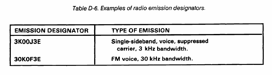
FM 24-2
D-5
FM 24-2
Appendix E
Special-Purpose Frequencies
E-1. Designation
6215.5 kHz Maritime mobile distress (voice)
National and international agreements have designated
8364 kHz Maritime search and rescue
special-purpose frequencies used for maritime distress,
search, and rescue and for aeronautical distress.
40.5 MHz Distress calling
E-2. Frequencies
121.5 MHz Aeronautical distress
Aircraft, ship, and survival craft stations may use the
123.1 MHz On-scene search and
following frequencies as long as they follow the ITU RRs.
rescue/auxillary
•
•
•
•
•
•
•
•
•
•
—
500 kHz
2182 kHz
3023 kHz
4125 kHz
5680 kHz
aeronautical (voice)
Maritime distress and calling
156.8 MHz Maritime distress and calling
Maritime distress and calling
243 MHz Aeronautical distress
Maritime search and rescue
401.0 to 406.1 MHz Search and rescue satellite
Maritime mobile distress (voice)
Maritime search and rescue
•
•
•
E-1
FM 24-2
Appendix F
Requesting Spectrum Management Assistance
F-1. Electromagnetic Interference Resolution
The multiplying signal systems in government and
nongovernment sectors have created substantial spectrum
congestion and have intensified competition for
electromagnetic spectrum space. Electromagnetic
interference (EMI) is the major threat to the continued and
expanded use of the electromagnetic spectrum. Within the
DOD, several agencies are tasked to assist in EMI
resolution. Within the Army, requests are generally sent to
the agencies shown below.
F-2. USAISEC
USAISEC provides consultation and propagation
engineering services to requestors in the Army and other
government agencies in the following areas:
Electromagnetic system performance analysis.
Electrical design and performance determination
•
•
•
•
•
•
•
•
•
of antennas.
Electromagnetic wave propagation advice.
Propagation forecasts and reliability predictions.
Service requests should include enough details to
permit task validation and prioritization. Requests should
be addressed as shown below.
MAIL: Commander
USAISEC
ATTN: ASQB-SET-P
Fort Huachuca, Arizona 85613-5300
MESSAGE: CDR USAISC FT HUACHUCA
AZ//ASQB-SET-P//
TELEPHONE: DSN 879-7685, Area Code
(602) 538-7685
F-3. DOD ECAC
DOD ECAC resources are available to research and
development activities and to operational commands.
ECAC support areas are as follows:
Spectrum planning.
Emission and susceptibility characteristics evalua-
tion.
Deployment and siting analysis.
Consultation services.
Data base listings.
DOD activities are encouraged to make direct contact
with the appropriate deputy director before submitting
requests for ECAC services. Once needs have been
defined, a written request for services should be sent to the
address shown below.
MAIL:
Army Deputy Director (CA)
ECAC, North Severn
Annapolis, Maryland 21402
MESSAGE: DIR ECAC ANNAPOLIS MD//CA//
TELEPHONE: DSN 281-2103, Area Code
(301) 267-2103
F-1
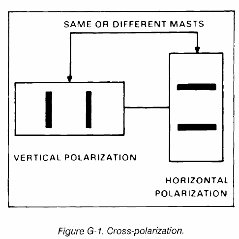
FM 24-2
Appendix G
Selecting Frequencies for Radio Multichannel Systems
G-1. Frequency Selection/LOS Multichannel
The method of frequency selection depends on the
equipment and the configuration of the multichannel
communications network. Much depends on the radio
relay network. Is it a simple isolated system or a complex
system? Are there more than two transmitters and
receivers operating at the same location? Does the
complex system have light and heavy traffic routes
interconnecting and crossing of radio systems? These
factors must be considered when selecting a proper,
workable frequency assignment plan. Technical manuals
covering that equipment describe the method used for
each piece of equipment. This appendix covers the radio
set, AN/GRC-103(V) band 1 since it is one of the current
radios used with pulse code modulation (PCM)
multiplexing equipment in radio relay systems. The
frequencies used in this appendix will be those of the
AFVGRC-103(V) (band 1220.0 to 404.5 MHz). MSE LOS
multichannel is the newest system fielded. It uses the radio
set, AN/GRC-226(V). Frequencies assigned for use are
provided by automated spectrum management by the SCC.
G-2. Interference Between Transmitters and
Receivers
The purpose of any frequency plan is to minimize the
effects of mutual interference. With a radio set operating
full duplex, the transmitting power is usually millions of
times greater than the power of the receiver’s signal. The
receiver must be able to reject the transmitter signal and
select the weak signal to which it is tuned.
To reject a transmitted signal, a receiver must be
separated from the transmitter by so many channels
according to the radio being used (see proper technical
manual).
This separation is called a guard band. When using the
AN/GRC-103(V), the transmitting frequencies at a station
must be well separated from the receiver frequencies to
guard against transmitter- to-receiver interference. This is
done by setting up a frequency guard band of 16.5 MHz (33
channels) between the transmitter and receiver frequency.
The receiving frequencies at a station must be well
separated from each other to guard against
receiver-to-receiver interference. This is done by operating
the receiver so at least three unused frequency channels
(1.5 MHz) separate the operating frequency of any two
receivers.
Two methods that reduce the required frequency
separation between systems from 16.5 MHz (33 channels)
to 5 MHz (10 channels) are cross-polarization and
separate masts.
Sometimes antennas on neighboring masts may be
cross- polarized to advantage. (loss-polarization is having
one antenna polarized in one plane (horizontal or vertical)
and the other antenna polarized in the other plane.
Cross-polarization results in a greater isolation between
antennas on the same mast or neighboring masts. It also
permits the separation between transmitting and receiving
frequencies on these antennas to be much smaller than with
noncross- polarized antennas (Figure G-l).
In applicable systems, using separate masts for
transmitters and receivers at a station reduces the
transmitter-to-receiver interference at that station. This
isolation can be further improved by using vertical
polarization for one antenna and horizontal polarization
for the other.
G-1
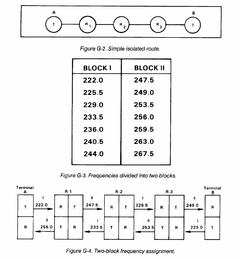
FM 24-2
G-3. Two-Block Frequency Assignment Plan
The two-block plan is used for simple isolated systems.
An isolated route is one which does not cross or connect
with any other radio-relay routes. For example, a system
may consist of two terminals and three repeaters (Figure
G-2) with the radios operating between 220.0 and 404.5
MHz.
To set up a two-block plan, arrange the frequencies in
numerical sequence (lowest to highest). Divide the
available frequencies into two blocks that contain equal
numbers of frequencies. Arrange them so each frequency
in the first block may be paired with a frequency in the
second block which is separated from the lower frequency
(Block I) by at least 16.5 MHz (Figure G-3).
Assign transmitting frequencies beginning at terminal A
by selecting a frequency from Block I and then from Block
II (Figure G-3). Assign all transmitting frequencies in an
A to B direction; then assign frequencies in the same
manner from a B to A direction (Figure G-4).
Ensure to maintain the minimum required
receiver-to-receiver separations at all sites where two or
more receivers are located. In this case, it would be the
three repeaters that would have to be checked for proper
receiver-to-receiver separation. For this reason,
frequencies from a specific block may not always be
assigned consecutively.
G-2

FM 24-2
The two-block plan can be used for a simple parallel
system. Tangent systems from any site in the parallel system
to other sites maybe established. This is possible because
from any site in a paralleled system all transmitter
frequencies are from one block, and the distant transmitter
would transmit on a frequency from the opposite block.
The two-block plan does not provide for alternate routing
or operating among three different sites. When systems
become too complex, the six-block ABM frequency
assignment plan should be used.
G-4. Six-Block ABM Frequency Assignment Plan
The six-block ABM plan is used for a complex system
with two or more transmitters and two or more receivers
at the same location (Figure G-5). (The letters A, B, and
M have no significant meaning.)
The ABM plan divides a broad frequency assignment
list (all or a large part of a band allocated) into six
frequency blocks (or lists) of suitable widths. Frequencies
obtained are divided equally among the six blocks. The
basic planning is then done in terms of these blocks.
Advantages of the six-block plan are shown below.
Any station can be connected with almost any
other station with minimum effect on the rest of
the network.
•
•
•
•
Planning is simplified.
Quick frequency changes can be accomplished
without any trouble.
By dividing all frequencies into six blocks all as-
signed frequencies are usable.
The necessary guard band between the transmit-
ter and receiver frequencies is obtained.
To use the ABM plan, designate each site with the letter
A, B, or M. Be sure that sites with the same letter are not
interconnected (Figure G-6). Following this rule, location
A can establish radio links with locations B or M but not
with another A.
Considering all possible radio links, a triangle can be
drawn as shown in Figure G-7A. Radio sets used in multi-
channel systems do not require transmitter-to-transmitter
separation; therefore, all transmitter frequencies can be
taken from the same block if necessary. Considering trans-
mitter frequencies only, six groups or blocks of frequencies
are required for the triangle. These blocks of frequencies
are numbered I through VI. At location A, I and II are the
transmitting frequencies and IV and V are the receiving
frequencies.
•
G-3
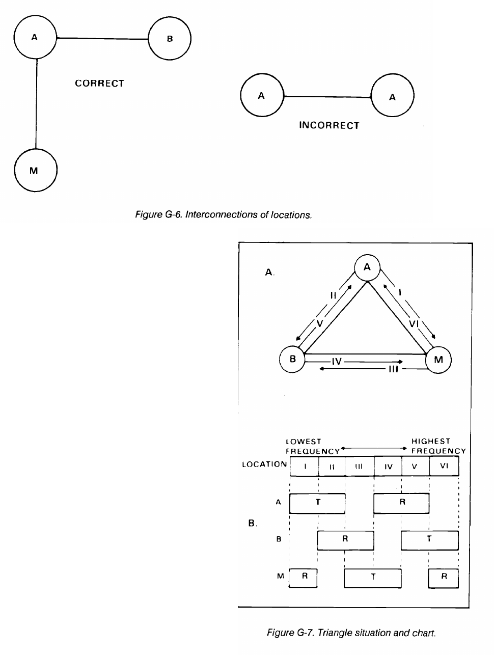
FM 24-2
To set up a system between A and M, the transmitter
frequencies at A must be from Block I and the receiver
frequencies at A must be from Block IV. Each system has
a designated block from which the frequencies are taken
(Figure G-7B). To set up a system from B to M, find the
block where B transmits and M receives. In this case, it is
VI.
Six blocks of frequencies are required when considering
the six transmitter frequencies from the triangle situation.
The required separations between the blocks (the
transmitter separation from receiver frequency by at least
16.5 MHz or more) are also considered. From the triangle
situation to a more complex situation such as Figure G-8,
it is necessary to determine the number of frequencies
required in each block. To do this, the system requirements
must be analyzed. (We no longer just divide the frequencies
equally into the six blocks.)
From Figure G-8, it can be seen that three transmitter
frequencies are required for the A to M systems. Thus, a
minimum of three frequencies are required in Block I for
A to M. Continue the system analysis by counting Block II
A to B frequencies, and then count Block III B to M
frequencies. It is not necessary to determine the number of
frequencies in Block IV, V, and VI because counting
Blocks I, II, and III gives half the total number of
frequencies for the entire system. Referring to Figures G-8
and G-9, note that in Block I a minimum of three
frequencies is required in the A-M direction. Since
frequencies on these systems are assigned in pairs, a total
of at least three frequencies will be required in Block IV.
Figure G-9 shows the requirements for the entire system.
G-4
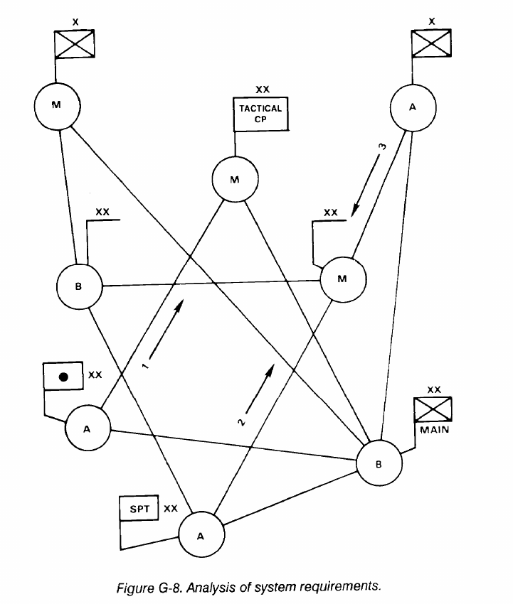
FM 24-2
When spare frequencies are assigned above the
required number for the systems, the spare frequencies
must be kept in numerical sequence with the other assigned
frequencies and divided equally among the blocks. For
example, if six spares are assigned, add them to the
sequential listing, then add one more frequency to each
block above the requirement (that is, Block 1, four
frequencies; Block II, five frequencies). These spare
frequencies may be used for displacement systems or
additional systems above the amount estimated for the
operation.
Frequencies may then be assigned to the system (Figure
G-10). The transmitting frequency is always located next to
the terminal or relay symbol. Refer to the analysis of system
requirements to determine what direction each system is
designated, such as A-M, A-B, or M-B; frequencies will be
assigned in pairs for each system. For example, in Figure
G-8, the first A-M system counted was from the division
artillery to the division tactical air command (TAC). From
Figure G-9, assign the first frequency in Block I (222.0
MHz) to division artillery for their transmit to TAC; at the
same time, assign the first frequency in Block IV (261.0
MHz) as the transmit frequency from TAC to division
artillery. If this procedure is followed exactly for each
system, then transmitter- to-receiver separation will not be
a problem. However, care must be taken at multichannel
relays and terminals to ensure that receiver-to-receiver
separations (1.5 MHz) are observed. Remember, the 1.5
MHz required separation pertains only to the
AN/GRC-103 in these examples. For other radio sets,
check the proper technical manuals.
The suggested method of assigning frequencies to radio
relay systems is to assign frequencies in the priority used
for establishing systems (command links, area links, logistic
G-5
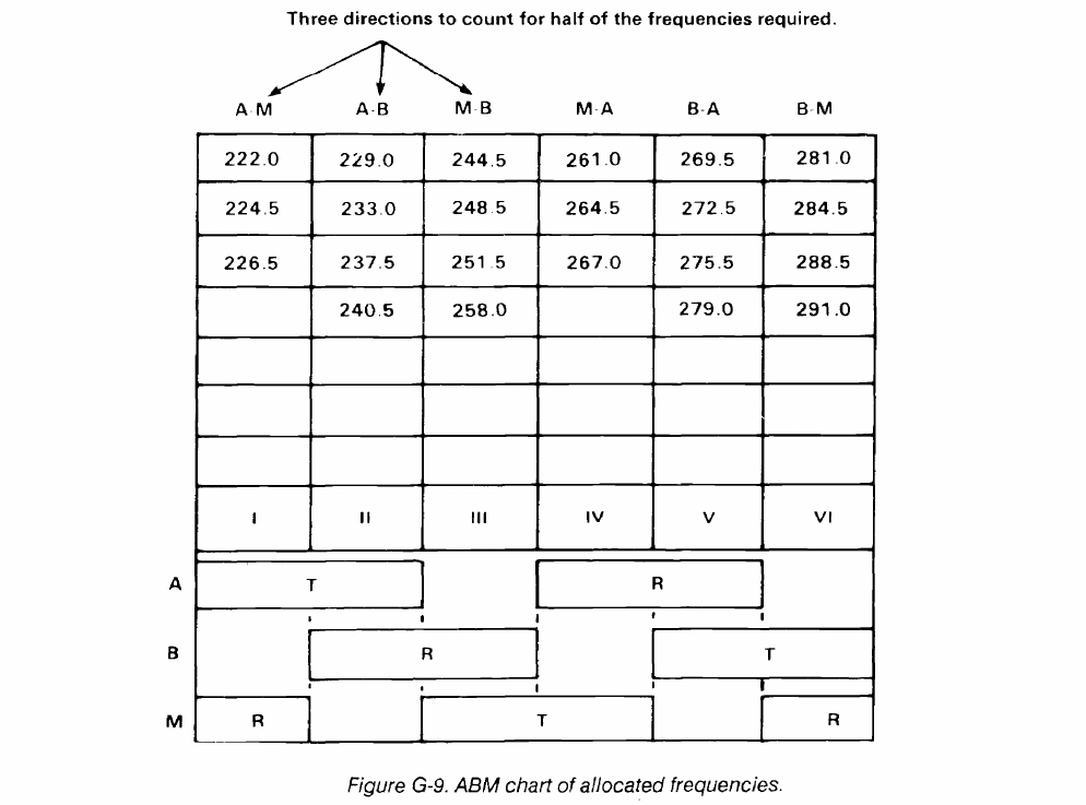
FM 24-2
links, and so on). Figure G-10 shows all frequencies
assigned to all systems with the proper guard bands.
G-5. Limitations of Frequency Assignment Plans
The frequency assignment plans that have been
discussed have limitations. Generally, a two-block
frequency plan will work for any simple isolated system
regardless of the radio sets used. However, when
frequencies are needed for complex systems with two or
more transmitters and receivers at the same location, new
problems arc often encountered.
The ABM plan is not the answer to eliminating all
mutual interference problems encountered within all
complex systems. When the frequencies used with some
radio sets are broken down into blocks according to the
ABM plan and other plans and the required frequency
separations for the particular radio sets are maintained,
problems with harmonics (multiple of a base frequency)
are sometimes encountered. This problem can become
even more complex in sophisticated frequency diversity
G-6
troposcatter systems where the base band signal applies to
two or more transmitters operating on different
frequencies and receives on two or more receivers.
Each radio set has different sensitivity, selectivity, and
other technical characteristics. When two or more systems
use the same site, frequency separation between the
transmit and receiver antenna on different masts becomes
a critical consideration. A receiver acted on by certain base
or harmonic frequencies from a transmitter located at the
same location will encounter mutual interference. Because
of this, a required frequency separation will have to be
maintained between transmitters and receivers. Proper
antenna orientation will have to be maintained between
antennas. The required frequency separation between
transmitters and receivers is not the same for all radio sets.
When the receivers of some radio sets are located
back-to-back as relay stations (repeaters), a different
frequency separation may be required between the
receivers than the frequency separation normally required
when the receivers are located separately at the same
location.
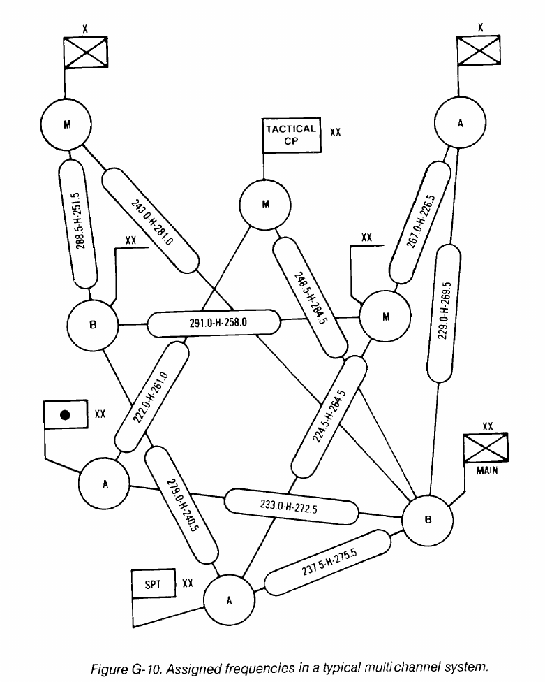
FM 24-2
At times, it may be possible to use the same set of
and selection. General details are given in the proper
frequencies (from a block of frequencies) more than once
technical manuals. This information will differ for each
within a particular complex communication system.
radio set.
Transmit frequencies that are the same or close to each
other can sometimes be transmitted in opposite or near
Figure G-11 shows a typical, completed,
opposite directions. The effectiveness of this method will
armored-infantry-mechanized (AIM) division
depend on the selectivity and sensitivity of the receivers
multichannel system diagram with the assigned operating
used and the overall distance between them.
frequencies using the single ABM plan.
Generally, the only sure way to minimize the effects of
mutual interference between transmitters and receivers is
to follow the proper instructions on spectrum management
G-7
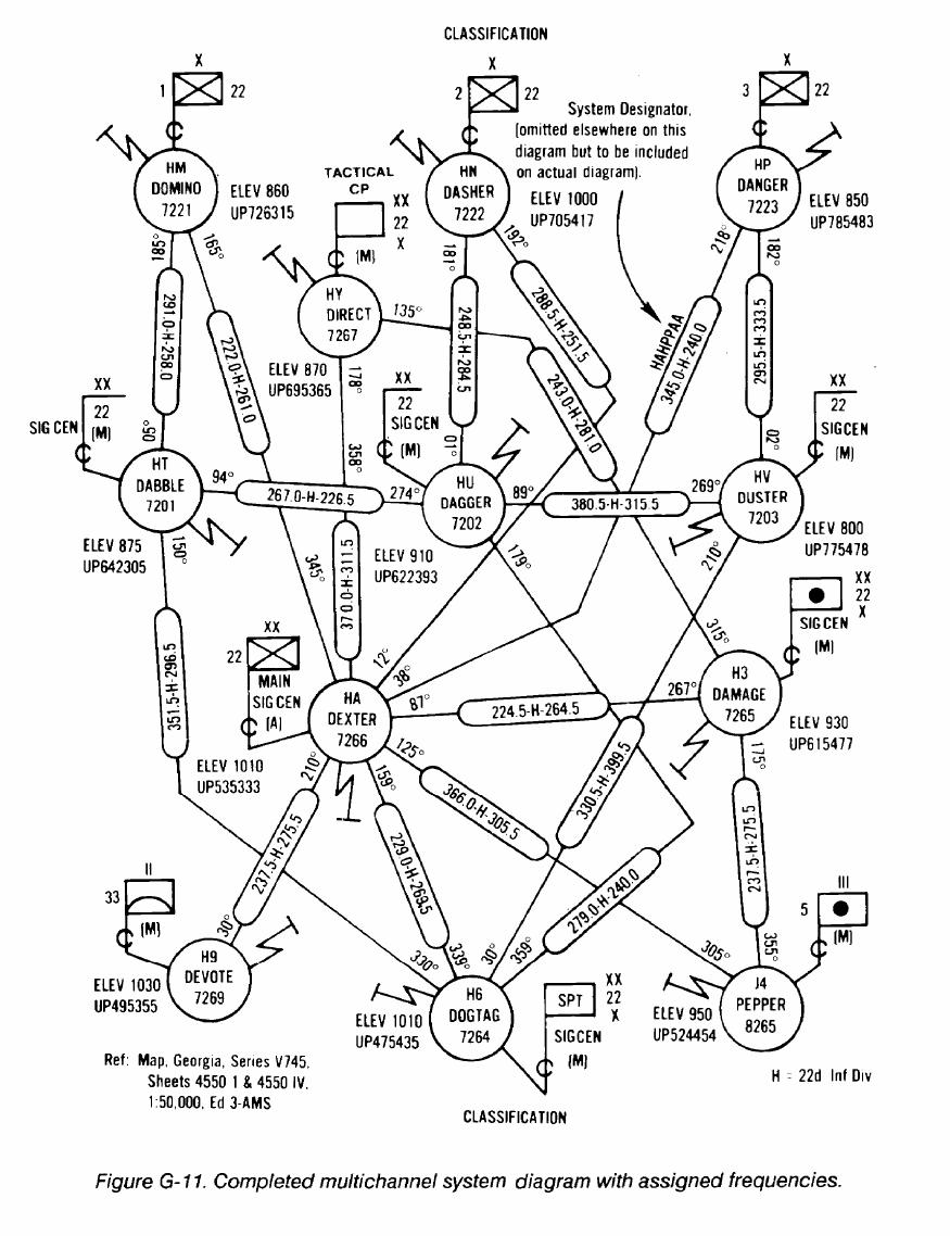
FM 24-2
G-8
FM 24-2
Appendix H
Hopset Construction
H-1. Introduction
A hopset is a list of frequencies the spectrum manager
authorizes a particular unit to use. A list of discrete
frequencies or ranges and groups of frequencies specify the
hopset.
Many frequency hopping (FH) or frequency agile
equipment is either fielded or under development. While
not all of these are communications equipment, the factors
in constructing hopsets are basically the same.
An FH or agile transmitter changes frequency within
a given frequency band in either a random, pseudorandom,
or fixed order. Generally, this is done as ECCM, but, in
some cases, is done when the equipment senses
interference on a specific frequency. The number of
frequencies used within the given frequency band can
range from a dozen to several thousand. Normally, the
more frequencies available in the required frequency band
for inclusions in the hopset, the more effectively the
equipment functions.
H-2. Construction Process
For this discussion, assume a corpswide hopset is being
constructed for SINCGARS. The corps G6 is the
frequency assignment authority for the band being used.
The entire construction process is actually one of
subtraction. The frequency resource needed by the FH or
agile transmitter is normally shared with other equipment,
such as between SINCGARS and MSE, and radio access
units (RAUs) and mobile subscriber radiotelephone
terminals (MSRTs). The spectrum manager must consider
the impact of the hopper on nonhopping assignments.
Possible interference to existing users must be evaluated,
and if the interference is determined to be unacceptable,
those frequencies must be deleted from the frequency
resource. The spectrum manager must also delete all
assignments that have been designated by corps, higher
headquarters, or civil authorities as restricted from the
frequency resource.
To develop a truly corpswide hopset, the spectrum
manager must consider all restrictions on frequency use
imposed by divisions within their areas of operation. It may
be that all of these frequencies were considered during the
process discussed above.
Any frequency restrictions that apply to corps boundary
areas must be considered and coordinated with the
adjacent corps. Frequencies restricted in the boundary
areas may be deleted from the frequency resource.
Using FH or agile transmitter in an aircraft can impose
additional restrictions. Not only does the process discussed
above apply, but also due to the increase in the radio
horizon, additional consideration with adjacent corps will
have to be made. This could lead to more frequencies being
deleted from the frequency resource. This results in a much
smaller hopset.
The spectrum manager starts the planning process by
compiling all the frequency requirements from the
subordinate units. He combines the subordinate unit
requirements with those of his echelon.
The spectrum manager assigns frequencies based on the
following criteria:
Network priority.
Equipment in use.
Equipment separation.
Retransmission requirements.
Frequency use restrictions.
The spectrum manager assigns the maximum number of
frequencies available in the area of operation and spreads
the frequencies in the hopsets across the widest possible
band to optimize ECCM capabilities. Spreading the
frequencies across the frequency band is more important
than increasing the total number of frequencies available.
Fifty frequencies spread from 30 to 88 MHz are more
effective than 100 frequencies from 35 to 40 MHz. Chances
are very slight that an enemy jammer can cover the entire
58 MHz range or even a small portion of it with enough
power to disrupt communications; however, a jammer
could barrage jam the entire 5 MHz range.
•
•
•
•
•
H-1
FM 24-2
The spectrum manager, with the signal planning
element, uses the BECs computer to assign frequencies to
hopsets. The computer mathematically manipulates the
frequencies based on the restrictions the spectrum
manager enters into the data base. The computer develops
hopsets by correlating the restrictions with available
resources.
Hopsets should maximize use of frequencies separate
from any collocated networks. This requires knowledge of
network structures and which nets are collocated. The
spectrum manager must work closely with G3/S3 to
minimize the effects on collocated networks.
To minimize possible interference between
SINCGARS and MSRTs/RAUs, SINCGARS can be
programmed to lock out certain frequencies from the
hopset. Neither BECS nor the MSE SCC can engineer
frequency use for both systems at the same time. The
spectrum manager must plan the MSRT/RAU frequencies
(up to 96 pairs) with the SCC (assigns MSRT/RAU
frequencies) and enter them into the BECS computer as
lockout sets. Frequency interference between the radio
systems is minimized, particularly the cosite systems.
H-3. Considerations
Corps and division level communications are currently
upgrading to MSE and fielding SINCGARS as a combat
net radio. Both systems use the same frequency band and
mutual interference has been noted.
Covehicular interference is the worst. Currently, there
is no technical solution and no planned fix until MSE and
SINCGARS are totally fielded. The area most affected by
•
•
•
•
•
•
H-2
this interference is the brigade area. Users in this area need
to be aware of the potential problem and given the
operational work-arounds to overcome the interference.
There are three methods/work-arounds that help
overcome the interference problem. No one method
eliminates all interference. The three methods are--
Time-sharing. The best answer to the vehicle
problem is prioritize the device needed by the
mission, situation, and echelon.
Spectrum-sharing. Lock out MSRT/RAU fre-
quencies on SINCGARS in the FH mode or
delete from frequency resource for SINCGARS
in the SINGLE-CHANNEL mode.
Antenna separation. The best alternative avail-
able for the fried locations but is not possible for
mobile users.
Common sense remains the best defense to resolve this
interference. Standard communications principles and
signal doctrine should be followed.
Use lowest power possible to maintain combat
net radio nets.
Keep transmissions short for combat net radio
and MSRT calls.
Keep vehicles using communications systems
separated during convoy and during halts.
FM 24-2
Appendix I
Station Classes
I-1. Stations (Alphabetical by Classes)
Station and associated station class (STC) symbols are
required for all frequency requests and assignments.
Station classes are used to identify the service in which the
transmitting station will operate.
All classes of earth stations are fixed earth stations
except--
•
•
•
•
•
•
A
L
S
M
TG
TJ
TO
TQ
TU
•
•
Those which have the following letters suffixed to
the STC symbol:
The earth station is aboard an aircraft.
The earth station is on a land vehicle.
The earth station is on board a ship.
The earth station is on any two or all three of
the above.
Those with the following STC symbols:
A Maritime Mobile-Satellite Earth Station.
An Aeronautical Mobile-Satellite Mobile Earth
Station.
An Aeronautical Radionavigation-Satellite
Mobile Earth Station.
A Maritime Radionavigation-Satellite Mobile
Earth Station.
A Land Mobile-Satellite Mobile Earth Station.
The suffix R shall be added to the established STC
symbol only if the station is used primarily as a repeater in
the bands shown below. For this purpose, a repeater
consists of a radio transmitter, a radio receiver, and
coupling between the two so as to retransmit unchanged in
intelligence the received signal.
29.89 - 50.00 MHz (Exclusive Government
Bands)
138.00 - 144.00 MHz
148.00 - 149.90 MHz
150.05 - 150.80 MHz
162.00 - 174.00 MHz
406.10 - 420.00 MHz
The STC symbols shown below are used on US
government frequency assignments as applicable.
Definitions followed by (RR) come from the ITU RR, 1982
edition.
FAB
AX
RLA
TB
TJ
EJ
Aeronautical Broadcast Station: An
aeronautical station which makes scheduled
broadcasts of meteorological information and
notices to airmen. (In certain instances, an
aeronautical broadcast station may be placed on
board a ship.)
Aeronautical Fixed Station: A station in the
aeronautical fixed service. (RR)
Aeronautical Marker Beacon Station: A
radionavigation land station in the aeronautical
radionavigation service which employs a marker
beacon.
Aeronautical Mobile-Satellite Earth Station: A
fixed earth station in the aeronautical
mobile-satellite service. (RR)
Aeronautical Mobile-Satellite Mobile Earth
Station: A mobile earth station in the
aeronautical mobile-satellite service. (RR)
Aeronautical Mobile-Satellite Space Station: A
space station in the aeronautical mobile-satellite
service.
I-1
FM 24-2
RLB
TZ
TO
EO
FA
FLEA
MOEA
FLU
Aeronautical Radiobeacon Station: A
radiobeacon station in the aeronautical
radionavigation service intended for the benefit
of aircraft.
Aeronautical Radionavigation-Satellite Earth
Station: A fixed earth station in the aeronautical
radionavigation-satellite service.
Aeronautical Radionavigation-Satellite Mobile
Earth Station: A mobile earth station in the
aeronautical radionavigation-satellite service.
(RR)
Aeronautical Radionavigation-Satellite Space
Station: A space station in the aeronautical
radionavigation-satellite service. (RR)
Aeronautical Station: A land station in the
aeronautical mobile service. In certain
instances, an aeronautical station may be
located, for example, on board ship or on a
platform at sea. (RR)
Aeronautical Telemetering Land Station: A
telemetering land station used in the flight
testing of manned or unmanned aircraft,
missiles, or major components thereof.
Aeronautical Telemetering Mobile Station: A
telemetering mobile station used in testing of
manned or unmanned aircraft, missiles, or
major components thereof.
Aeronautical Utility Land Station: A land station
TW
located at airdome control towers and used for
control of ground vehicles and aircraft on the
ground at airdromes.
MOU
Aeronautical Utility Mobile Station: A mobile
station used for communication at airdromes
with the aeronautical utility land station, the
airdrome control station, the Federal Aviation
Administration flight service station, ground
vehicles, and aircraft on the ground. (All
transmissions shall be subject to the control of
the airdrome control station and shall be
discontinued immediately when so requested by
the airdrome control operators.)
MA
Aircraft Station: A mobile station in the
aeronautical mobile service, other than a
I-2
FAC
ROA
FB
EB
EV
BC
BT
FC
EW
TP
TE
XM
survival craft station, located on board an
aircraft. (RR)
Airdrome Control Station: An aeronautical
station providing communication between an
airdrome control tower and aircraft.
Altimeter Station: A radionavigation mobile
station in the aeronautical radionavigation
service which employs a radio altimeter.
Base Station: A land station in the land mobile
service. (RR)
Broadcasting-Satellite Space Station (sound
broadcasting): A space station (sound
broadcasting) in the broadcasting-satellite
service. (RR)
Broadcasting-Satellite Space Station
(television): A space station (television) in the
broadcasting-satellite service. (RR)
Broadcasting Station (sound): A station (sound)
in the broadcasting service. (RR)
Broadcasting Station (television): A station
(television) in the broadcasting service. (RR)
Coast Station: A land station in the maritime
mobile service. (RR)
Earth Exploration-Satellite Earth Station: An
earth station in the earth exploration-satellite
service. (RR)
Earth Exploration-Satellite Space Station: A
space station in the earth exploration-satellite
service. (RR)
Earth Station (receiving): An earth station used
for receiving. (RR) (TP is not used on
applications.)
Earth Station (transmitting): An earth station
used for transmitting. (RR) (TE is not used on
applications.)
Experimental Composite Station: An
experimental station used in experimental
operations of a complex nature not readily
specified or used in operation which is a
FM 24-2
XC
XD
XE
XR
EX
XT
TC
EC
FX
FLEB
composite of two or more of the established
experimental categories.
Experimental Contract Developmental Station:
An experimental station used for the evaluation
or testing under government contract of
electronics equipment or systems in a design or
development stage.
Experimental Developmental Station: An
experimental station used for evaluation or
testing of electronics equipment or systems in a
design or development stage.
Experimental Export Station: An experimental
station intended for export and used for the
evaluation or testing of electronics equipment
or systems in the design or development stage.
Experimental Research Station: An
experimental station used in basic studies
concerning scientific investigations looking
toward the improvement of the art of
radiocommunications.
Experimental Station: A station utilizing radio
waves in experiments with a view to the
development of science or technique. This
definition does not include amateur stations.
(RR) (EX is not used on applications.)
Experimental Testing Station: An experimental
station used for the evaluation or testing of
electronics equipment or systems, including site
selection and transmission path surveys, which
have been developed for operational use.
Fixed-Satellite Earth Station: An earth station in
the fixed-satellite service. (RR)
Fixed-Satellite Space Station: A space station in
the fixed-satellite service. (RR)
Fixed Station: A station in the fixed service.
(RR)
Flight Telemetering Land Station: A
telemetering land station the emissions of which
are used for telemetering to a balloon; to a
booster or rocket, excluding a booster or rocket
in orbit about the earth or in deep space; or to
an aircraft, excluding a station used in the flight
testing of an aircraft.
MOEB
Flight Telemetering Mobile Station: A
FAT
RLG
FXH
FLH
MOH
ES
TY
TU
EU
ML
telemetering mobile station the emissions if
which are used for telemetering from a balloon;
from a booster or rocket, excluding a booster or
rocket in orbit about the earth or in deep space;
or from an aircraft, excluding a station used in
the flight testing of an aircraft.
Flight Test Station: An aeronautical station used
for the transmission of essential
communications in connection with the testing
of aircraft or major components of aircraft.
Glide Path (Slope) Station: A radionavigation
land station in the aeronautical radionavigation
service which employs the Instrument Landing
System Glide Path.
Hydrologic and Meteorological Fixed Station: A
fixed station the emissions of which are used for
the automatic transmission of either hydrologic
or meteorological data, or both.
Hydrologic and Meteorological Land Station: A
land station the emissions of which are used for
the automatic transmission of either hydrologic
or meteorological data, or both.
Hydrologic and Meteorological Mobile Station:
A mobile station the emissions of which are
used for the automatic transmission of either
hydrologic or meteorological data, or both.
Intersatellite Space Station: A space station in
the intersatellite service. (RR)
Land Mobile-Satellite Earth Station: A fixed
earth station in the land mobile-satellite service.
(RR)
Land Mobile-Satellite Mobile Earth Station: A
mobile earth station in the land mobile-satellite
service. (RR)
Land Mobile-Satellite Space Station: A space
station in the land mobile-satellite service. (RR)
Land Mobile Station: A mobile station in the
land mobile service capable of surface
I-3
FM 24-2
FL
RLL
RLN
FCB
RLM
TI
TG
EG
TX
TQ
EQ
WXD
I-4
movement within the geographical limits of a
country or continent. (RR)
Land Station: A station in the mobile service
not intended to be used while in motion. (RR)
Localizer Station: A radionavigation land
station in the aeronautical radionavigation
service which employs an Instrument Landing
System Localizer.
Loran Station: A long distance radionavigation
land station transmitting synchronized pulses.
Hyperbolic lines of position are determined by
the measurement of the difference in the time of
arrival of these pulses.
Marine Broadcast Station: A coast station
which scheduled broadcasts of time,
meteorological, and hydrographic information.
Maritime Radiobeacon Station: A radiobeacon
station in the maritime radionavigation service
intended for the benefit of ships.
Maritime Mobile-Satellite Earth Station: An
earth station in the maritime mobile-satellite
service at a specified fried point. (RR)
Maritime Mobile-Satellite Mobile Earth Station:
A mobile earth station in the maritime
mobile-satellite service. (RR)
Maritime Mobile-Satellite Space Station: A
space station in the maritime mobile-satellite
service. (RR)
Maritime Radionavigation-Satellite Earth
Station: A fixed earth station in the maritime
radionavigation-satellite service. (RR)
Maritime Radionavigation-Satellite Mobile
Earth Station: A mobile earth station in the
maritime radionavigation-satellite service. (RR)
Maritime Radionavigation-Satellite Space
Station: A space station in the maritime
radionavigation-satellite service. (RR)
Meteorological Radar Station: A station in the
meteorological aids service employing radar.
TM
EM
MO
OE
OD
RLO
MAP
MLP
MOP
MRP
MSP
RLC
WXB
Meteorological-Satellite Earth Station: An
earth station in the meteorological-satellite
service. (RR)
Meteorological-Satellite Space Station: A space
station in the meteorological-satellite service.
(RR)
Mobile Station: A station in the mobile service
intended to be used while in motion or during
halts at unspecified points. (RR)
Oceanographic Data Interrogating Station: A
station in the maritime mobile service the
emissions of which are used to initiate, modify,
or terminate functions of equipment directly
associated with an oceanographic data station,
including the station itself. (RR)
Oceanographic Data Station: A station in the
maritime mobile service located on a ship, buoy,
or other sensor platform the emissions of which
are used for transmission of oceanographic
data. (RR)
Omnidirectional Range Station: A
radionavigation land station in the aeronautical
radionavigation service providing direct
indication of the bearing (omnibearing) of that
station from an aircraft.
Portable Aircraft Station: A portable station
operating in the aeronautical mobile service.
Portable Land Mobile Station: A portable
station operating in the land mobile service.
Portable Mobile Station: A portable station
operating in the mobile service.
Portable Radiolocation Station: A portable
station operating in the radiolocation service.
Portable Ship Station: A portable station
operating in the maritime mobile service.
Radar Beacon (racon) Station: A station which
employs a radar beacon (racon).
Radar Beacon Precipitation Gage Station: A
transponder station in the meteorological aids
FM 24-2
RA
MOB
TF
TL
EF
RG
LR
MR
RL
service, the emissions of which are used for
telemetering.
Radio Astronomy Station: A station in the radio
astronomy service. (RR) (This is always a
receiving station.)
Radio Beacon Mobile Station: A mobile station
the emissions of which are used to determine its
location.
Radiodetermination-Satellite Earth Station: A
fixed earth station in the
radiodetermination-service. (RR)
Radiodetermination-Satellite Mobile Earth
Station: A mobile earth station in the
radiodetermination-satellite service. (RR)
Radiodetermination-Satellite Space Station: A
space station in the radiodetermination-satellite
service. (RR)
Radio Direction-Finding Station: A
radiodetermination station using radio
direction-finding. (RR)
Radiolocation Land Station: A station in the
radiolocation service not intended to be used
while in motion. (RR)
Radiolocation Mobile Station: A station in the
radiolocation service intended to be used while
in motion or during halts at unspecified points.
(RR)
Radionavigation Land Station: A station in the
radionavigation service not intended to be used
while in motion. (RR)
RLTM
Radionavigation Land Test Station
(Maintenance Test Facility): A radionavigation
land station in the aeronautical radionavigation
service which is used as a radionavigation
calibration station for the transmission of
essential information in connection with the
testing and calibration of aircraft navigational
aids, receiving equipment, and interrogators at
predetermined surface locations. The primary
purpose of this facility is to permit maintenance
testing by aircraft radio service personnel.
RLTO
RO
TN
EN
RLR
WXR
Radionavigation Land Test Station (operational
Test Facility): A radionavigation land station in
the aeronautical radionavigation service which
is used as a radionavigation calibration station
for the transmission of essential information in
connection with the testing and calibration of
aircraft navigational aids, receiving equipment,
and interrogators at predetermined surface
locations. The primary purpose of this facility is
to permit the pilot to check a radionavigation
system aboard the aircraft prior to takeoff.
Radionavigation Mobile Station: A station in
the radionavigation service intended to be used
while in motion or during halts at unspecified
points. (RR)
Radionavigation-Satellite Earth Station: An
earth station in the radionavigation-satellite
service. (RR)
Radionavigation-Satellite Space Station: A
space station in the radionavigation-satellite
service. (RR)
Radio Range Station: A radionavigation land
station in the aeronautical radionavigation
service providing radial equisignal zones. (In
certain instances a radio range station may be
placed on board a ship.)
Radiosonde Station: A station in the
meteorological aids service employing a
radiosonde.
WXRG
Radiosonde Ground Station: A station in the
meteorological aids service employing a ground
station associated with a radiosonde.
MS
Ship Station: A mobile station in the maritime
mobile service located on board a vessel which
is not permanently moored, other than a
survival craft station. (RR)
SN
Sounder Network Station: A station equipped
with an ionosphere sounder used for the
real-time selection of frequencies for
operational communication circuits.
SP
Sounder Prediction Station: A station equipped
with an ionosphere sounder for real-time
monitoring of upper atmosphere phenomena or
I-5
FM 24-2
TT
ET
TH
EH
ME
TD
ED
TETD
TETR
TR
ER
TK
to obtain data for the prediction of propagation
conditions.
Space Operation Earth Station: An earth station
in the space operation service. (RR)
Space Operation Space Station: A space station
in the space operation service.
Space Research Earth Station: An earth station
in the space research service. (RR)
Space Research Space Station: A space station
in the space research service. (RR)
Space Station: A station located on an object
which is beyond, is intended to go beyond, or
has been beyond, the major portion of the
earth’s atmosphere. (RR) (ME is not used on
applications.)
Space Telecommand Earth Station: An earth
station the emissions of which are used for
space telecommand. (RR)
Space Telecommand Space Station: A space
station which receives emissions used for space
telecommand. (RR)
Space Telecommand Transmitting Earth
Station: For an emergency position - indicating
radiobeacon (EPIRB) in a mobile-satellite
service.
Space Telemetering Transmitting Earth Station:
For an emergency position - indicating
radiobeacon (EPIRB) in a mobile-satellite
service.
Space Telemetering Earth Station: An earth
station which receives emissions used for space
telemetering. (RR)
Space Telemetering Space Station: A space
station the emissions of which are used for
space telemetering. (RR)
Space Tracking Earth Station: An earth station
which transmits or receives emissions used for
space tracking. (RR)
EK
TETK
SS
EE
FLEC
MOEC
RLS
FAD
MAD
FBD
FCD
Space Tracking Space Station: A space station
which transmits or receives and retransmits
emissions used for space tracking. (RR)
Space Tracking Transmitting Earth Station: For
an emergency position - indicating radiobeacon
(EPIRB) in a mobile-satellite service.
Standard Frequency and Time Signal Station: A
station in the standard frequency and time
signal service. (RR)
Standard Frequency and Time Signal-Satellite
Space Station: A space station in the standard
frequency and time signal-satellite service. (RR)
Surface Telemetering Land Station: A
telemetering land station the emissions of which
are intended to be received on the surface of the
earth.
Surface Telemetering Mobile Station: A
telemetering mobile station located on the
surface of the earth and the emissions of which
are intended to be received in the surface of the
earth.
Surveillance Radar Station: A radionavigation
land station in the aeronautical radionavigation
service employing radar to display the presence
of aircraft within its range. (In certain instances,
a surveillance radar station may be placed on
board a ship.)
Telecommand Aeronautical Station: A land
station in the aeronautical mobile service the
emissions of which are used for terrestrial
telecommand.
Telecommand Aircraft Station: A mobile station
in the aeronautical mobile service the emissions
of which are used for terrestrial telecommand.
Telecommand Base Station: A land station in
the land mobile service the emissions of which
are used for terrestrial telecommand.
Telecommand Coast Station: A land station in
the maritime mobile service the emissions of
which are used for terrestrial telecommand.
I-6
FM 24-2
FXD
FLD
MLD
MOD
MSD
FXE
FLE
MOE
Telecommand Fixed Station: A fixed station the
emissions of which are used for terrestrial
telecommand.
Telecommand Land Station: A land station the
emissions of which are used for terrestrial
telecommand.
Telecommand Land Mobile Station: A mobile
station in the land mobile service the emissions
of which are used for terrestrial telecommand.
Telecommand Mobile Station: A mobile station
the emissions of which are used for terrestrial
telecommand.
Telecommand Ship Station: A mobile station in
the maritime mobile service the emissions of
which are used for terrestrial telecommand.
Telemetering Fixed Station: A fixed station the
emissions of which are used for telemetering.
Telemetering Land Station: A land station the
emissions of which are used for telemetering.
Telemetering Mobile Station: A mobile station
the emissions of which are used for telemetering,
1-2. Stations (Alphabetical Symbols)
STC symbols shown below are used on US government
frequency assignments as applicable.
AX
BC
BT
EB
EC
ECED
ECEK
Aeronautical Fixed Station.
Broadcasting Station (sound).
Broadcasting Station (television).
Broadcasting-Satellite Space Station (sound
broadcasting).
Fixed-Satellite Space Station.
Space Telecommand Space Station in the
fixed-satellite service.
Space Tracking Space Station in the
fixed-satellite service.
ECER
ED
EE
EF
EFED
EFEK
EFER
EG
EGED
EGEK
EGER
EH
EHED
EHEK
EHER
EJ
EJED
EJEK
EJER
Space Telemetering Space Station in the
fixed-satellite service.
Space Telecommand Space Station.
Standard Frequency and Time Signal-Satellite
Space Station.
Radiodetermination-Satellite Space Station.
Space Telecommand Space Station in the
radiodetermination-satellite service.
Space Tracking Space Station in the
radiodetermination-satellite service.
Space Telemetering Space Station in the
radiodetermination-satellite service.
Maritime Mobile-Satellite Space Station.
Space Telecommand Space Station in the
maritime mobile- satellite service.
Space Tracking Space Station in the maritime
mobile-satellite service.
Space Telemetering Space Station in the
maritime mobile-satellite service.
Space Research Space Station.
Space Telecommand Space Station in the space
research service.
Space Tracking Space Station in the space
research service.
Space Telemetering Space Station in the space
research service.
Aeronautical Mobile-Satellite Space Station.
Space Telecommand Space Station in the
aeronautical mobile-satellite service.
Space Tracking Space Station in the
aeronautical mobile-satellite service.
Space Telemetering Space Station in the
aeronautical mobile-satellite service.
I-7
FM 24-2
EK
Space Tracking Space Station.
EM
Meteorological-Satellite Space Station.
EMED
Space Telecommand Space Station in the
meteorological-satellite service.
EMEK
Space Tracking Space Station in the
meteorological-satellite service.
EMER
Space Telemetering Space Station in the
meteorological-satellite service.
EN
Radionavigation-Satellite Space Station.
ENED
Space Telecommand Space Station in the
radionavigation-satellite service.
ENEK
Space Tracking Space Station in the
radionavigation-satellite service.
ENER
Space Telemetering Space Station in the
radionavigation-satellite service.
EO
Aeronautical Radionavigation-Satellite Space
Station.
EOED
Space Telecommand Space Station in the
aeronautical radionavigation-satellite service.
EOEK
Space Tracking Space Station in the aeronautical
radionavigation-satellite service.
EOER
Space Telemetering Space Station in the
aeronautical radionavigation-satellite service.
EQ
Maritime Radionavigation-Satellite Space
Station.
EQED
Space Telecommand Space Station in the
maritime radionavigation-satellite service.
EQEK
Space Tracking Space Station in the maritime
radionavigation-satellite service.
EQER
Space Telemetering Space Station in the
maritime radionavigation-satellite service.
ER
Space Telemetering Space Station.
ES
Intersatellite Space Station.
ESED
ESEK
ESER
ET
ETED
ETEK
ETER
EU
EUED
EUEK
EUER
EV
EW
EWED
EWEK
EWER
EX
Space Telecommand Space Station in the
intersatellite service.
Space Tracking Space Station in the intersatellite
service.
Space Telemetering Space Station in the
intersatellite service.
Space Operation Space Station.
Space Telecommand Space Station in the space
operation service.
Space Tracking Space Station in the space
operation service.
Space Telemetering Space Station in the space
operation service.
Land Mobile-Satellite Space Station.
Space Telecommand Space Station in the land
mobile-satellite service.
Space Tracking Space Station in the land
mobile-satellite service.
Space Telemetering Space Station in the land
mobile-satellite service.
Broadcasting-Satellite Space Station (television).
Earth Exploration-Satellite Space Station.
Space Telecommand Space Station in the earth
exploration-satellite service.
Space Tracking Space Station in the earth
exploration-satellite service.
Space Telemetering Space Station in the earth
exploration-satellite service.
Experimental Station.
FA
Aeronautical Station.
FAB
Aeronautical Broadcast Station.
FAC
Airdome Control Station.
I-8
FM 24-2
FAD
FAT
FB
FC
FCB
FL
FLD
FLE
FLEA
FLEB
FLEC
FLH
FLU
FX
FXD
FXE
FXH
LR
MA
MAD
MAP
ME
ML
MLP
MO
MOB
Telecommand Aeronautical Station.
Flight Test Station.
Base Station.
Coast Station.
Marine Broadcast Station.
Land Station.
Telecommand Land Station.
Telemetering Land Station.
Aeronautical Telemetering Land Station.
Flight Telemetering Land Station.
Surface Telemetering Land Station.
Hydrologic and Meteorological Land Station.
AeronauticaI Utility Land Station.
Fixed Station.
Telecommand Fixed Station.
Telemetering Fixed Station.
Hydrologic and Meteorological Fixed Station.
Radiolocation Land Station.
Aircraft Station.
Telecommand Aircraft Station
Portable Aircraft Station.
Space Station.
Land Mobile Station.
Portable Land Mobile Station.
Mobile Station.
Radiobeacon Mobile Station.
MOD
Telecommand Mobile Station.
MOE
Telemetering Mobile Station.
MOEA
Aeronautical Telemetering Mobile Station.
MOEB
Flight Telemetering Mobile Station.
MOEC
Surface Telemetering Mobile Station.
MOH
MOP
MOU
MR
MRP
MS
MSD
MSP
OD
OE
RA
RG
RL
RLA
RLB
RLC
RLG
RLL
RLM
RLN
RLO
Hydrologic and Meteorological Mobile Station.
Portable Mobile Station.
Aeronautical Utility Mobile Station.
Radiolocation Mobile Station.
Portable Radiolocation Station.
Ship Station.
Telecommand Ship Station.
Portable Ship Station.
Oceanographic Data Station.
Oceanographic Data Interrogating Station.
Radio Astronomy Station.
Radio Direction-Finding Station.
Radionavigation Land Station.
Aeronautical Marker Beacon Station.
Aeronautical Radiobeacon Station.
Radar Beacon (racon) Station.
Glide Path (Slope) Station.
Localizer Station.
Marine Radiobeacon Station.
Loran Station.
Omnidirectional Range Station.
I-9
FM 24-2
RLR
RLS
RLTM
RLTO
RO
ROA
SN
SP
SS
TB
TBTD
TBTK
TBTR
TC
TCTD
TCTK
TCTR
TD
TE
TETD
TETK
I-10
Radio Range Station.
Surveillance Radar Station.
Radionavigation Land Test Station
(Maintenance Test Facility).
Radionavigation Land Test Station
(Operational Test Facility).
Radionavigation Mobile Station.
Altimeter Station.
Sounder Network Station.
Sounder Prediction Station.
Standard Frequency and Time Signal Station.
Aeronautical Mobile-Satellite Earth Station.
Space Telecommand Earth Station (fixed) in the
aeronautical mobile-satellite service.
Space Tracking Earth Station (fixed) in the
aeronautical mobile-satellite service.
Space Telemetering Earth Station (fixed) in the
aeronautical mobile-satellite service.
Fixed-Satellite Earth Station.
Space Telecommand Earth Station in the
fixed-satellite service.
Space Tracking Earth Station in the
fixed-satellite service.
Space Telemetering Earth Station in the
fixed-satellite service.
Space Telecommand Earth Station.
Earth Station (transmitting).
Telecommand Transmitting Earth Station for an
EPIRB in a mobile-satellite service.
Space Tracking Transmitting Earth Station for
an EPIRB in a mobile-satellite service.
TETR
TF
TFTD
TFTK
TFTR
TG
TGTD
TGTK
TGTR
TH
THTD
THTK
THTR
TI
TITD
TITK
TITR
TJ
TJTD
Space Telemetering Transmitting Earth Station
for an EPIRB in a mobile-satellite service.
Radiodetermination-Satellite Earth Station.
Space Telecommand Earth Station (fixed) in the
radiodetermination-satellite service.
Space Tracking Earth Station (fixed) in the
radiodetermination-satellite service.
Space Telemetering Earth Station (fixed) in the
radiodetermination-satellite service.
Maritime Mobile-Satellite Mobile Earth Station.
Space Telecommand Earth Station (mobile) in
the maritime mobile-satellite service.
Space Tracking Earth Station (mobile) in the
maritime mobile-satellite service.
Space Telemetering Earth Station (mobile) in
the maritime mobile-satellite service.
Space Research Earth Station.
Space Telecommand Earth Station in the space
research service.
Space Tracking Earth Station in the space
research service.
Space Telemetering Earth Station in the space
research service.
Maritime Mobile-Satellite Earth Station.
Space Telecommand Earth Station (fixed) in the
maritime mobile-satellite service.
Space Tracking Earth Station (fixed) in the
maritime mobile-satellite service.
Space Telemetering Earth Station (fixed) in the
maritime mobile-satellite service.
Aeronautical Mobile-Satellite Mobile Earth
Station.
Space Telecommand Earth Station (mobile) in
the aeronautical mobile-satellite service.
FM 24-2
TJTK
TJTR
TK
TL
TLTD
TLTK
TLTR
TM
TMTD
TMTK
TMTR
TN
TNTD
TNTK
TNTR
TO
TOTD
TOTK
Space Tracking Earth Station (mobile) in the
aeronautical mobile-satellite service.
Space Telemetering Earth Station (mobile) in
the aeronautical obile-satellite service.
Space Tracking Earth Station.
Radiodetermination-Satellite Mobile Earth
Station.
Space Telecommand Earth Station (mobile) in
the radiodetermination-satellite service.
Space Tracking Earth Station (mobile) in the
radiodetermination-satellite service.
Space Telemetering Earth Station (mobile) in
the radiodetermination-satellite service.
Meteorological-Satellite Earth Station.
Space Telecommand Earth Station in the
meteorological-satellite service.
Space Tracking Earth Station in the
meteorological-satellite service.
Space Telemetering Earth Station in the
meteorological-satellite service.
Radionavigation-Satellite Earth Station.
Space Telccommand Earth Station in the
radionavigation-satellite service.
Space Tracking Earth Station in the
radionavigation-satellite service.
Space Telemetering Earth Station in the
radionavigation-satellite service.
Aeronautical Radionavigation-Satellite Mobile
Earth Station.
Space Telecommand Earth Station (mobile) in
the aeronautical radionavigation-satellite
service.
Space Tracking Earth Station (mobile) in the
aeronautical radionavigation-satellite service.
TOTR
Space Telemetering Earth Station (mobile) in
the aeronautical radionavigation-satellite
service.
TP
Earth Station (receiving).
TQ
Maritime Radionavigation-Satellite Mobile
Earth Station.
TQTD
Space Telecommand Earth Station (mobile) in
the maritime radionavigation-satellite service.
TQTK
Space Tracking Earth Station (mobile) in the
maritime radionavigation-satellite service.
TQTR
Space Telemetering Earth Station (mobile) in
the maritime radionavigation-satellite service.
TR
Space Telemetering Earth Station.
TT
Space Operation Earth Station.
TTTD
Space Telecommand Earth Station in the space
operation service.
TITK
Space Tracking Earth Station in the space
operation service.
TTTR
Space Telemetering Earth Station in the space
operation service.
TU
Land Mobile-Satellite Mobile Earth Station.
TUTD
Space Telecommand Earth Station (mobile) in
the land mobile-satellite service.
TUTK
Space Tracking Earth Station (mobile) in the
land mobile-satellite service.
TUTR
Space Telemetering Earth Station (mobile) in
the land mobile-satellite service.
Earth Exploration-Satellite Earth Station.
TWTD
Space Telecommand Earth Station in the earth
exploration-satellite service.
TWTK
Space Tracking Earth Station in the earth
exploration-satellite service.
TWTR
Space Telemetering Earth Station in the earth
exploration-satellite service.
TW
I-11
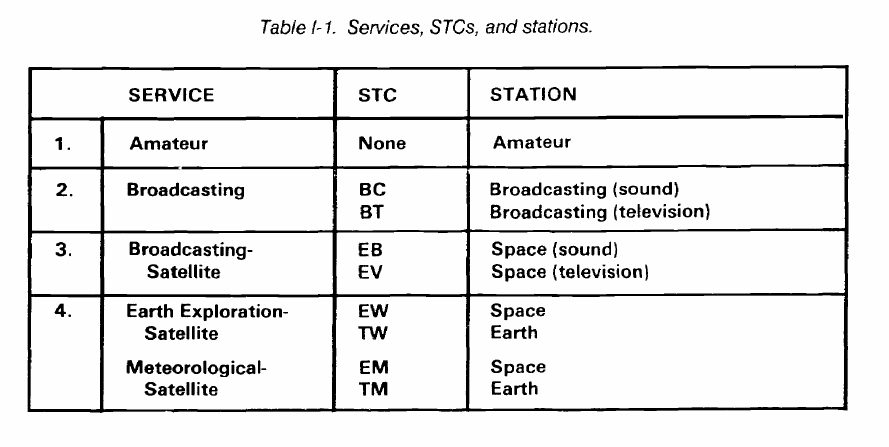
FM 24-2
TX
TXTD
TXTK
TXTR
TY
TYTD
TYTK
TYTR
TZ
TZTD
TZTK
Maritime Radionavigation-Satellite Earth
Station
Space Telecommand Earth Station (fixed) in the
maritime radionavigation-satellite service.
Space Tracking Earth Station (fixed) in the
maritime radionavigation-satellite service.
Space Telemetering Earth Station (fixed) in the
maritime radionavigation-satellite service.
Land Mobile-Satellite Earth Station.
Space Telecommand Earth Station (fixed) in the
land mobile-satellite service.
Space Tracking Earth Station (fixed) in the land
mobile-satellite service.
Space Telemetering Earth Station (fixed) in the
land mobile-satellite service.
Aeronautical Radionavigalion-Satellite Earth
Station.
Space Telecommand Earth Station (fixed) in the
aeronautical radionavigalion-satellite service.
Space Tracking Earth Station (fixed) in the
aeronautical radionavigation-satellite service.
TZTR
WXB
WXD
WXR
XC
XD
XE
XM
XR
XT
Space Telemetering Earth Station (fixed) in the
aeronautical radionavigation-satellite service.
Radar Beacon Precipitation Gage Station.
Meteorological Radar Station.
Radiosonde Station.
Experimental Contract Developmental Station.
Experimental Developmental Station.
Experimental Export Station.
Experimental Composite Station.
Experimental Research Station.
Experimental Testing Station.
I-3. Services, Station Classes, and Stations
Use Table I-1 to determine the proper STC symbol to
use versus the service in which the transmitting station will
operate. Frequency bands are allocated to services based
on the US Government Table of Frequency Allocations.
I-12
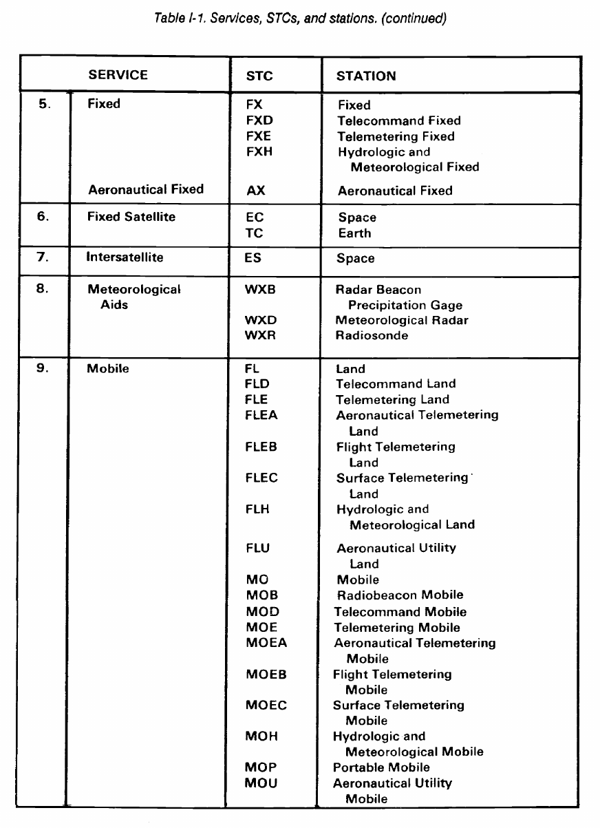
FM 24-2
I-13
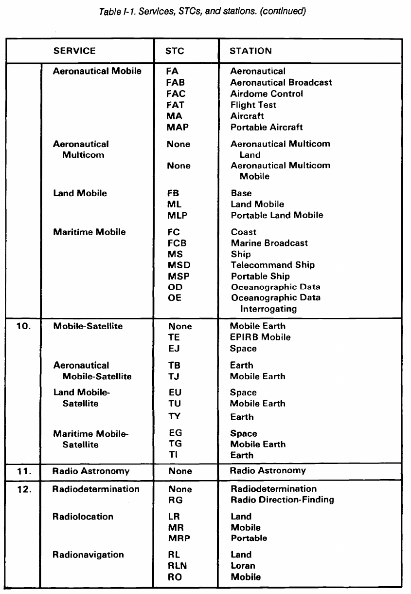
FM 24-2
I-14
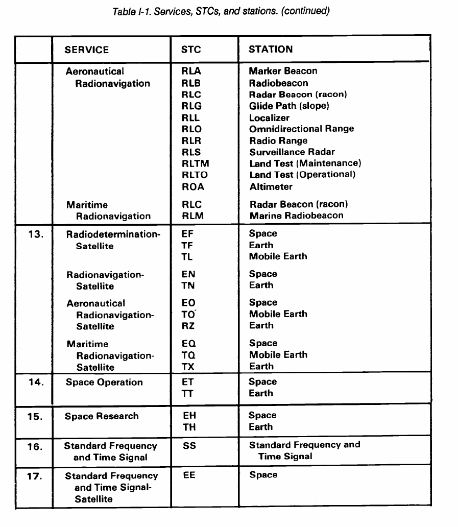
FM 24-2
I-15
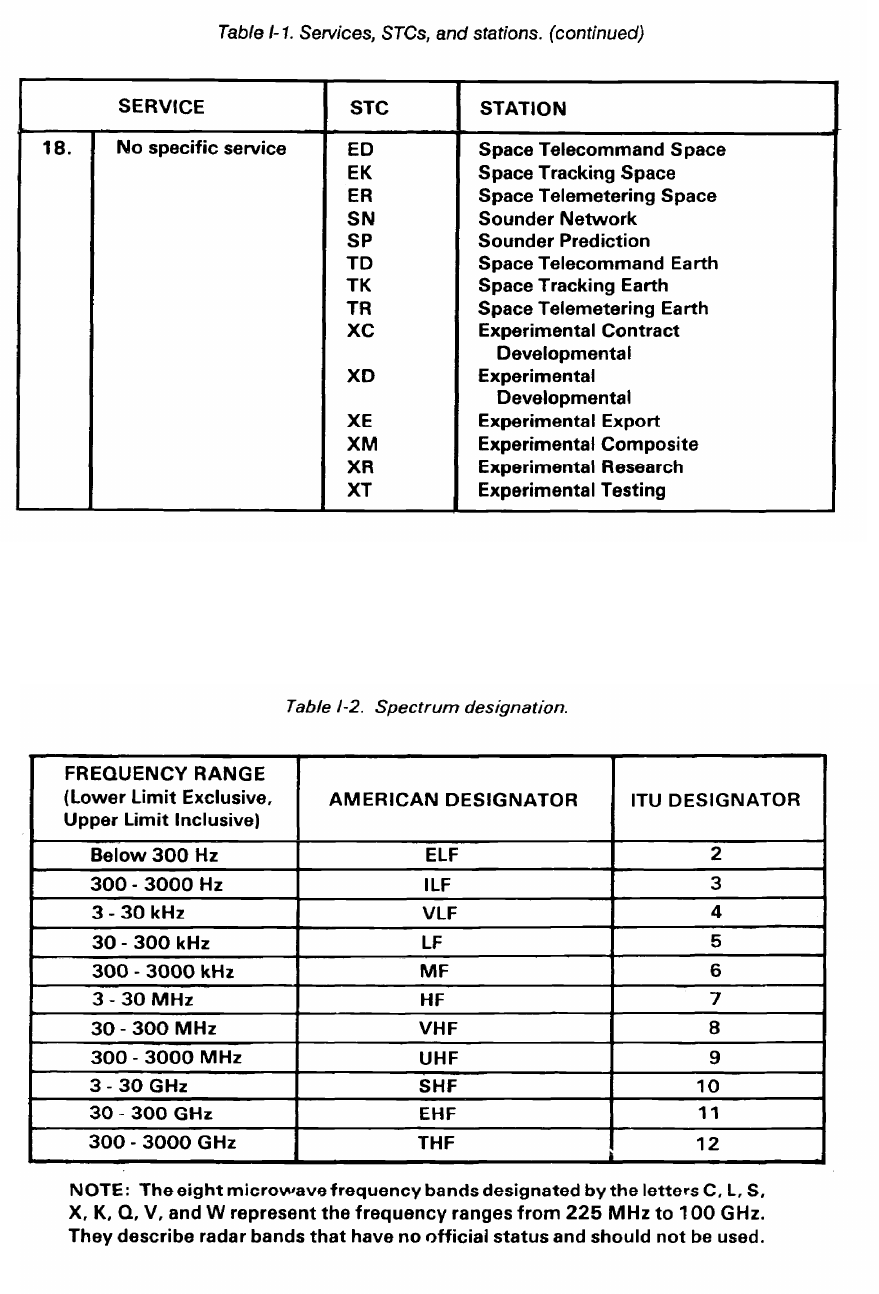
FM 24-2
I-4. Spectrum Designation of Frequency
Table I-2 shows that spectrum designation of
frequency is a method of referring to a range or band of
communications frequencies. In America, the designator
is a two- or three-letter abbreviation for the name. In the
ITU, the designator is numeric.
I-16
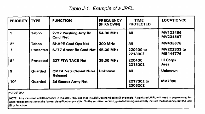
FM 24-2
Appendix J
The Joint Restricted Frequency List
J-1. General
The JRFL is a management tool designed to minimize
frequency conflicts between friendly communica-
tions/noncommunications emitters and friendly jamming
equipment. More specifically, the JRFL is a time and
geographical listing of prioritized frequencies essential to
the conduct of the battle and restricted from targeting by
friendly ECM. Consisting of taboo, guarded, and protected
frequencies, the JRFL assists staff members involved in
spectrum management.
J-2. Purpose
The JRFL is constructed and maintained throughout
the battle to graphically depict the commander’s priorities
for electromagnetic spectrum use. It displays to the staff
and operational forces the frequencies guarded for signal
intelligence (SIGINT) use or restricted from friendly
jamming due to criticality of friendly operations.
Candidate nodes/nets are submitted for ECM protection
of the Joint Communications-Electronics Warfare System.
This submission includes net designation, frequency, type
equipment, type modulation, location, time period, and a
short justification. Figure J-1 shows an example of a JRFL.
J-3. Definitions
Taboo frequencies are any friendly functions/frequen-
cies of such importance that they must never be deliberate-
ly jammed or interfered with by friendly forces. These
functions/frequencies include international distress, stop
buzzer, safety, and controller frequencies. These func-
tions/frequencies are generally long-standing; however,
they can be time-oriented, in that, as the combat/exercise
situation changes, the restriction can be removed by the
originating headquarters.
Protected functions/frequencies are those friendly
functions/frequencies used for a particular operation,
identified and protected to prevent them from being
inadvertently jammed by friendly forces while active EW
operations are directed against hostile forces. The
functions/frequencies are of such critical importance that
jamming is restricted unless absolutely necessary or until
coordination with the using unit is made. They are
time-oriented, can change with the tactical situation, and
are updated periodically.
Guarded functions/frequencies are enemy
functions/frequencies that are currently being exploited for
combat information and intelligence. A guarded
function/frequency is time-oriented, in that the list changes
as the enemy assumes different combat postures. These
functions/frequencies can be jammed after the commander
has weighed the potential operational gain against the loss
of technical and tactical information.
J-1
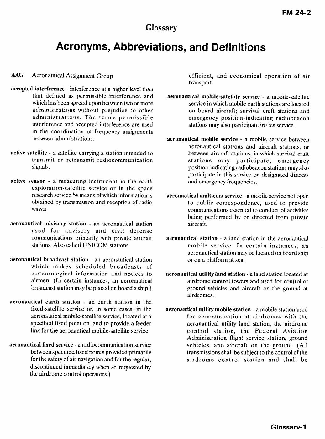
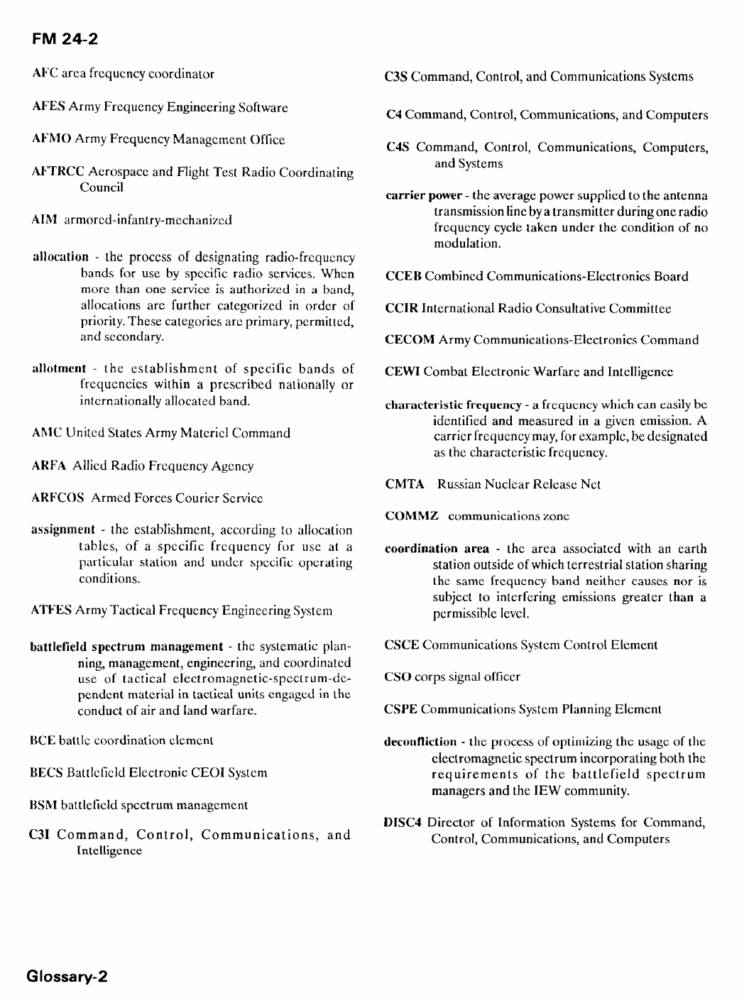
Glossary-5
FM 24-2
References
SOURCES USED
These are the sources quoted or paraphrased in
this publication.
International and National Regulations
Radio Regulations, Published by ITU, Geneva.
1982 Edition.
Manual of Regulations and Procedures for Federal
Radio Frequency Management, US
Department of Commerce, National Telecom-
munications and Information Administration.
Washington, DC 20230. 30 May 1986.
Quadripartite Standardization Agreements
(QSTAG)
QSTAG 679. Millimeter Waves and Lasers (30
GHz and above). 25 November 1985.
QSTAG 715. Battlefield Spectrum Management
HF (1.5 - 30 MHz Band). 21 May 1985.
QSTAG 716. Battlefield Spectrum Management
VHF (30 - 88 MHz Band). 25 July 1985.
QSTAG 718. Battlefield Spectrum Management
UHF (225 - 400 MHz Band). 05 June 1985.
QSTAG 719. Battlefield Spectrum Management
Tactical Radio Relay and Tropospheric
Scatter Systems. 19 August 1985.
QSTAG 721. Battlefield Spectrum Management:
Radar, Position Navigation, Tactical
Sensor System and Multifunction Infor-
mation Distribution System. 19 August 1985.
QSTAG 723. Battlefield Spectrum Management:
Deconfliction. 20 June 1985.
Standardization Agreement (STANAG)
STANAG 6004. MIJI Reporting. 28 March 1984.
DOCUMENTS NEEDED
These documents must be available to the
intended users of this publication.
Allied Communications Publication (ACP)
*ACP 125 US Supp-1. Communications Instructions
Radiotelephone Procedures For Use by United
States Ground Forces. 01 November 1985.
ACP 190 US Supp - 1(B). Guide to Frequency
Planning. 01 October 1977.
ACP 191A. Ionospheric Sounder Operations.
August 1987.
Army Regulations (ARs)
*AR 5-12. Army Management of the Electro-
magnetic Spectrum. 15 May 1983.
*AR 105-3. Reporting Meaconing, Intrusion,
Jamming and Interference of Electromag-
netic Systems. 31 July 1986.
AR 105-24. Radio Frequency and Call Sign
Assignments for US Army Communications-
Electronics Activities. 28 March 1977.
AR 105-86. Performing Electronic Countermeasures
in the United States and Canada.
August 1983.
Field Manuals (FMs)
*FM 11-32. Combat Net Radio Operations.
15 October 1990.
*FM 11-50. Combat Communications Within the
Division (Heavy and Light). 04 April 1991.
*FM 11-92 (HTF). Combat Communications Within
the Corps (How to Fight). 01 November 1978.
FM 24-1. Signal Support in the AirLand Battle.
15 October 1990.
FM 24-11. Tactical Satellite Communications.
20 September 1990.
*FM 24-16. Communications-Electronics:
Operations, Orders, Records, and Reports.
07 April 1978.
*FM 24-33. Communications Techniques: Electronic
Counter-Countermeasures. 17 July 1990.
*FM 24-35. Signal Operation Instructions The
“SOI.” 26 October 1990.
*This source was also used to develop this
publication.
References-1
FM 24-2
Forms
Joint Chiefs of Staff Publication (JCS)
DA Form 2028. Recommended Changes to Publi-
cations and Blank Forms. February 1974.
DD Form 1494. Application for Equipment Fre-
quency Allocation. February 1987.
READINGS RECOMMENDED
These readings contain relevant supplemental
information.
Department of Defense Directive (DOD)
DOD Directive 4650.1. Management and Use of
the Radio Frequency Spectrum.
December 1974.
Field Manuals (FM)
FM 11-23. Theater Communications Command
(Army). 28 November 1972.
FM 11-65. High Frequency Radio Communica-
tions. 31 October 1978.
JCS PUB 1-02. Department of Defense Dictionary
of Military and Associated Terms.
01 June 1987.
Office of Management and Budget Circular (OMB)
*OMB Circular A-11. Preparation and Submission
of Budget Estimates. July 1990.
TRADOC Pamplet (PAM)
TRADOC Pam 525-23. US Army Operational
Concept for Army Tactical Battlefield
Spectrum Management (ATDO).
18 February 1983.
Technical Manual (TM)
TM 11-5800-213-L. List of Applicable Publications
(LOAP) for Communications Electronic
Equipment. 01 October 1986.
*This source was also used to develop this
publication.
References-2